1
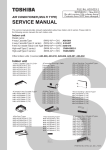
6. External View of P.C. Board
Terminator (SW01)
52
85
7. Address Setup
In addition to set up the central control address, it is necessary to change the indoor unit number.
(Line/Indoor/Group address).
For details, refer to TCC-LINK Adapter Installation Manual.
12-3. How to set up central control address number
When connecting the indoor unit to the central control remote controller using TCC-LINK adapter, it is necessary to set up the central control address number.
• The central control address number is displayed as the line No. of the central control remote controller.
1. Setup from remote controller at indoor unit side
* If you use the network adapter P.C. board, it is effective only when No. 7 of setup switch SW01 on P.C.
board is turned off.
<Procedure> Perform setup while the unit stops.
1
TEST
VENT
Push +
buttons for 4 seconds or more.
When group control is executed, first the unit No. RLL is displayed and all the indoor units in the group
control are selected. In this time, fans of all the selected indoor units are turned on. (Fig. 1)
(Keep RLL displayed status without pushing
button.)
In case of individual remote controller which is not group-controlled, Line address and Indoor unit address
are displayed.
UNIT
2
3
4
Using temperature setup
Using timer time
table (Table 1).
Push
SET
TIME
TEMP.
buttons, specify item code
buttons, select the setup data. The setup data is shown in the right
button. (OK if display goes on.)
• To change the item to be set up, return to Procedure
5
Push
TEST
03.
(Fig.1)
2.
button.
SET DATA
The status returns to usual stop status.
UNIT No.
R.C.
(Table 1)
No.
TEMP.
Setup data
Central control address No.
0001
0002
0003
:
0064
1
2
3
:
64
0099
Unset (Setup at shipment from factory)
2
1
5
– 115 –
FILTER
RESET TEST
ON / OFF
TIMER SET
FAN
MODE
TIME
SWING/FIX
VENT
SET
CL
UNIT
3
1
4