1
www.TeamBuick.com
350-375B TRANSMISSION
7C- 1
TURBO HYDRA-MATIC 350-375B AUTOMATIC
TRANSMISSION
CONTENTS
DESCRIPTION AND OPERATION:
Description of Turbo Hydra-Matic 35O-375B Automatic Transmission
7C- 1
Sequence for Turbo Hydra-Matic 35O-375B Transmission Diagnosis
Turbo Hydra-Matic 35O-375B Transmission Oil Checking Procedures
External Oil Leaks
Vacuum Modulator Diagnosis Procedure
Turbo Hydra-Matic 35O-375B Trouble Diagnosis Chart
Hydraulic Pressure Checks
7C- 3
7C- 3
DIAGNOSIS:
MAINTENANCE AND ADJUSTMENTS:
Detent Cable Adjustment
Removal of Propeller Shaft Yoke Seal, Speedometer Drive Gear and Governor
Fluid Recommendations Refer to O Section Maintenance
Removal of Oil Pan, Oil Filter and Valve Body
7C- 3
7C- 4
7C- 5
7C-12
7C-16
7C-17
7C-19
MAJOR REPAIR:
Transmission Assembly Removal and Installation
7C-19
Preliminary Instructions
7C-20
Removal of Converter, Holding Tool, Converter and Vacuum Modulator
7C-21
Removal of Extension Housing, Lip Seal and Bushing
7C-22
Installing Extension Housing Bushing and Lip Seal
7C-22
Removal of Oil Pump Screen, Governor Screen and Check Balls
7C-23
Removal of Manual Shaft, Inner Lever, Parking Pawl and Intermediate Servo Piston
7C-24
Removal of Pump Assembly, Cushion Spring, Intermediate Clutch Plates and Overrun
Brake Band
7C-25
Removal of Direct and Forward Clutch Assemblies, Input Ring Gear and Output Carrier
7C-25
Removal of Sungear Shell, Low and Reverse Clutch Support Assembly, Low and Reverse
Clutch Plates and Reaction Carrier
7C-26
Removal of Output Ring Gear and Shaft Assembly, and Output Ring Gear to Case Needle
Bearing Assembly
7C-28
Removal of Low and Reverse Clutch Piston and Case Bushing
7C-29
Removal and Installation of Intermediate Clutch Accumulator
7C-30
Disassembly and Reassembly of Oil Pump Assembly
7C-31
Disassembly and Reassembly of Direct Clutch
7C-35
Disassembly and Reassembly of Forward Clutch Assembly
7C-38
Disassembly and Reassembly of Sungear to Drive Shell
7C-42
Disassembly and Reassembly of Low and Reverse Roller Clutch Assembly
7C-43
Valve Body Disassembly Inspection and Reassembly
7C-44
Assembly of Transmission from Major Parts and Units
7C-45
Converter Checking Procedure
7C-56
Installation of Governor Bushing
7C-57
SPECIFICATIONS:
General Specifications
7C-60
DESCRIPTION AND OPERATION
DESCRIPTION OF TURBO HYDRA-MATIC
350-375B AUTOMATIC TRANSMISSION
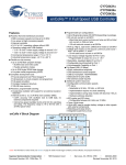
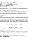
The Turbo Hydra-Matic 35O-375B transmission, see Fig
ure 7C-1, is a fully automatic unit consisting primarily of
3-element hydraulic torque converter and two planetary
gear sets. Four multiple-disc clutches, two roller clutches,
and an intermediate overrun band provide the friction
elements required to obtain the desired function of the two
planetary gear sets.
The 3-element torque converter consists of a pump, tur
bine and a stator assembly. The stator is mounted on a one
way roller clutch which will allow the stator to turn clock
wise, but not counterclockwise. References to clockwise
and counterclockwise are determined by looking toward
rear of car.
7C- 2
www.TeamBuick.com
Operation of the turbo-hydramatic 375B transmission is
1975 BUICK SERVICE MANUAL
The torque converter is of welded construction and is
serviced as a complete assembly. The unit is filled with oil
and is attached to the engine crankshaft by a flywheel,
thus aJways rotates at engine speed. The converter pump
is an integral part of the converter housing, therefore, the
pump blades, rotating at engine speed, set the oil within
the converter into motion and direct it to the turbine,
causing the turbine to rotate.
As the oil passes throughout the turbine it is traveling in
such a direction that if it were not redirected by the stator
it would hit the rear of the converter pump blades and
impede its pumping action. So at low turbine speeds, oil
is redirected by the stator to the converter pump in such
a manner that it actually assists the converter pump to
deliver power, or multiply engine torque.
As turbine speed increases, the direction of oil leaving the
turbine changes and flows against the rear side of the
stator vanes in a clockwise direction. Since the stator is
now impeding the smooth flow of oil, its roller clutch
releases and it revolves freely on its shaft. Once the stator
becomes inactive, there is no further multiplication of
engine torque within the converter. At this point, the
converter is merely acting as a fluid coupling as both the
converter pump and turbine are being driven at approxi
mately the same speed.
A hydraulic system pressurized by a gear type pump pro
vides the working pressure required to operate the friction
elements and automatic controls.
identical to the 350, with the physical difference being an
increase in the number of direct clutch plates from four to
five. This will increase torque capacity.
High Output Oil Pump - To be selected for maximum
output from the current production assemblies.
Close Limit Governor and Modulator - To provide more
precise pressure control.
High Capacity Transmission Oil Cooler - Same as used
with current Upper Series THM-400 transmissions.
External control connections to the transmission are:
1. Manual Linkage - To select the desired operating range.
2. Engine Vacuum - To operate the vacuum modulator.
3. Cable Control - To operate the detent valve.
The following shift points are approximate and vary de
pending on rear axle ratio.
In Drive-range at minimum throttle the 1st shift will oc
cur at 9-14 mph, and the 2nd shift at 15-20 mph. At
maximum throttle the 1st shift will occur at 40-50 mph,
and the 2nd shift at 68-78 mph.
The detent valve is activated by a cable that is connected
to the accelerator lever assembly. When the throttle is half
open, the valve is actuated causing throttle downshift at
speeds below 50 mph. When the throttle is fully open the
detent valve is actuated causing the transmission to down
shift from approximately 3-1 at speeds below 40 mph and
3-2 below 75 mph.
-CONVERTER ASSEMBLY
CONVERTER PUMP
INTERMEDIATE
( 1-2) CLUTCH
SUN GEAR & DRIVE SHELL
,— FORWARD CLUTCH
INPUT RING GEAR
INTERMEDIATE
OVERRUN BAND
OUTPUT CARRIER
LOW & REVERSE
ROLLER CLUTCH
DIRECT ( 2-3
CLUTCH
EXTENSION
HOUSING
SPEEDO DRIVE GEAR
OUTPUT SHAFT
GOVERNOR - DRIVEN GEAR
VALVE BODY
FILTER-
(OIL PUMPSUCTION]
STATOR
INPUT SHAFT
INTERMEDIATE O.R
ROLLER CLUTCH
—OIL PUMP COVER
OUTPUT RING GEAR
REACTION CARRIER
LOW & REVERSE CLUTCH
LOW & REVERSE CLUTCH SUPPORT
-OIL PUMP BODY
*—STATOR SHAFT
Figure 7C-1 - 35O-375B Automatic Transmission
5B7C1
TROUBLE DIAGNOSIS
www.TeamBuick.com
SEQUENCE FOR TURBO HYDRA-MATIC 350-375B
TRANSMISSION DIAGNOSIS
1. Check and correct oil level.
2. Check detent cable adjustment.
3. Check and correct vacuum line and fittings.
4. Check and correct manual linkage.
5. Road test car.
a. Install oil pressure gage.
b. Road test using all selective ranges, noting when discre
350-375B TRANSMISSION
1. Degrease underside of transmission.
2. Road test to get unit at operating temperature.
3. Inspect for leak with engine running.
4. With engine off, check for oil leaks due to the raised oil
level caused by drain back.
Possible Points of Oil Leaks
1. Transmission Oil Pan Leak.
a. Attaching bolts not correctly torqued.
pancies in operation or oil pressure occur.
b. Improperly installed or damaged pan gasket.
c. Attempt to isolate the unit or circuit involved in the
c. Oil pan gasket mounting face not flat.
malfunction.
d. If engine performances indicates an engine tune-up is
required, this should be performed before road testing is
completed or transmission correction attempted. Poor en
gine performance can result in rough shifting or other
malfunctions.
TURBO HYDRA-MATIC 350-375B TRANSMISSION
CHECKING PROCEDURES
Before diagnosis of any transmission complaint is at
tempted, there must be understanding of oil checking
procedure and what appearance the oil should have. Many
times a transmission malfunction can be traced to low oil
level or improper reading of dipstick. Due to the transmis
sion fluid that is now being used it may appear to be
darker and have a stronger odor. This is normal, and not
a positive sign of required maintenance or transmission
2. Extension Housing.
a. Attaching bolts not correctly torqued.
b. Rear seal assembly damaged or improperly installed.
c. Square seal, extension to case, damaged or improperly
installed.
3. Case Leak.
a. Filler pipe "O" ring seal damaged or missing; misposi-
tion of filler pipe bracket to engine.
b. Modulator assembly "O" ring seal damaged or improp
erly installed.
c. Detent cable connector "0* ring seal damaged or im
properly installed.
d. Governor cover not tight, gasket damaged or leak be
failure.
tween case face and gasket.
Also when the dipstick is removed, it should be noted
whether the oil is devoid of air bubbles or not. Oil with air
bubbles gives an indication of an air leak in the suction
lines, which can cause erratic operation and slippage. Wa
ter in the oil imparts a milky, pink cast to the oil and can
e. Speedometer gear "O" ring damaged.
cause spewing.
7C- 3
f. Manual shaft seal damaged or improperly installed.
g. Line pressure tap plug loose.
4. Leak at Front of Transmission.
a. Front pump seal leaks.
EXTERNAL OIL LEAKS
(1) Seal lip cut. Check converter hub, etc.
Determining Source of Oil Leak
(2) Bushing moved and damaged. Oil return hole plugged.
Before attempting to correct an oil leak, the actual source
of the leak must be determined. In many cases, the source
of the leak can be deceiving due to ;/wind flow" around the
engine and transmission.
The suspected area should be wiped clean of all oil before
inspecting for the source of the leak. Red dye is used in
the transmission oil at the assembly plant and will indicate
(3) No oil return hole.
b. Front pump attaching bolts loose or bolt washer type
seals damaged or missing.
c. Front pump housing "0" ring damaged or cut.
d. Converter leak in weld area.
if the oil leak is from the transmission.
e. Porous casting (pump).
The use of a "Black Light" to locate the point at which
the oil is leaking is helpful. Comparing the oil from the
leak to that on the engine or transmission dipstick, when
viewed by black light, will determine the source of the leak
5. Oil Comes Out Vent Pipe.
- engine or transmission.
Oil leaks around the engine and transmission are generally
carried toward the rear of the car by air stream. For
example, a transmission oil filler tube to case leak will
sometimes appear as a leak at the rear of the transmission.
In determining the source of a leak, proceed as follows:
a. Transmission over-filled.
b. Water in oil.
c. Foreign material between pump and case or between
pump cover and body.
d. Case - porous near converter bosses. Front pump cover
or housing oil channels shy or stock near breather.
e. Pump to case gasket mis-positioned.
7C- 4
www.TeamBuick.com
1975 BUICK SERVICE MANUAL
Case Porosity Repair
Turbo Hydra-Matic 35O-375B transmission external oil
leaks caused by case porosity can be successfully repaired
with the transmission in the car by using the following
recommended procedures:
1. Road test and bring the transmission to operating tem
perature, approximately 190 degrees F.
2. Raise car on a hoist or jack stand, engine running, and
locate source of oil leak. Check for oil leaks in Low, Drive,
and Reverse.
3. Shut engine off and thoroughly clean area to be repaired
with a suitable cleaning solvent and a brush - air dry.
A clean, dry soldering acid brush can be used to clean the
area and also to apply the epoxy cement or equivalent.
4. Using instructions of the manufacturer, mix a sufficient
amount of epoxy (or equivalent) to make the repair. Make
certain the area to be repaired is fully covered.
5. Allow cement to cure for
3 hours before starting
VACUUM MODULATOR DIAGNOSIS PROCEDURE
A failed vacuum modulator can cause one or more of the
following complaints.
1. Harsh upshifts and downshifts.
2. Delayed upshifts.
3. Soft upshifts and downshifts.
4. Slips in low, drive and reverse.
5. Transmission overheating.
6. Engine burning transmission oil.
If any one of the above complaints are encountered, the
modulator must be checked.
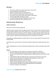
The vacuum modulator, see Figure 7C-2, has three areas
to be checked. If any one of the three (3) areas fail to pass
the prescribed checks, the modulator must be replaced.
BELLOWS
DIAPHRAGM
SLEEVE
engine.
6. Road test and check for leaks.
CONVERTER STATOR OPERATION DIAGNOSIS
1. The stator assembly freewheels in both directions.
If the stator roller clutch becomes ineffective, the stator
assembly freewheels at all times in both directions. With
this condition, the vehicle will tend to have poor accelera
tion from a standstill. At speeds above 30-35 m.p.h., the
vehicle may act normal. If poor acceleration problems are
noted, it should first be determined that the exhaust sys
tem is not blocked, the engine is in good tune and the
transmission is in first (1st) gear when starting out.
If the engine will freely accelerate to high r.p.m. in Neu
tral (N), it can be assumed that the engine and exhaust
system are normal. Driving the vehicle in Reverse (R) and
checking for poor performance will help determine if the
stator is freewheeling at all times.
2. The stator assembly remains locked up at all times.
If the stator assembly remains locked up at all times, the
engine r.p.m. and vehicle speed will tend to be limited or
restricted at high speeds. The vehicle performance when
accelerating from a standstill will be normal. Engine over
heating may be noted. Visual examination of the converter
may reveal a blue color from the overheating that will
result.
Under both conditions 1 or 2, if the converter has been
removed from the transmission, the stator roller clutch
can be checked by inserting a finger into the splined inner
race of the roller clutch and trying to turn the race in both
directions. The inner race should turn freely in the clock
wise direction, but not turn or be very difficult to turn in
the counterclockwise direction.
(NOTE: Do not use such items as the pump cover or
stator shaft to turn the race as the results may be mislead
ing.)
7C-42
Figure 7C-2 - Vacuum Modulator Assembly
1. Bellows Comparison Check.
To check bellows load proceed as follows:
a. Insert one end of the comparison gage J-24466 into the
suspected modulator sleeve. Insert the opposite end of the
gage into a known, good modulator of the same part
number as the suspected modulator. This part number of
the modulator assembly is located on the back side of the
modulator.
b. Holding the modulators in a horizontal position, see
Figure 7C-3, bring them slowly together under pressure.
The modulator bellows in question, if bad, will reach the
center line of the comparison gage before the known good
modulator lines up with the outer gage line. See Figure
7C-4.
If the modulator bellows in question is good, both modula
tor assemblies will be within the outer gage lines as the
assemblies are slowly brought together. See Figure 7C-5.
2. Vacuum Diaphragm Leak Check.
Turn modulator so vacuum line stem points downward. If
transmission oil comes out the vacuum diaphragm is bad.
Gasoline and/or water vapor may settle in the vacuum
side of the modulator. If this is found WITHOUT the
presence of oil, the modulator MUST NOT BE
CHANGED.
www.TeamBuick.com350-375B TRANSMISSION
MODULATOR PART NUMBER
IS LOCATED ON BACK SIDE
OF THE
COMPARISON^
GAUGE
7C- 5
dence of lubricity. If the solution does not have the feel of
oiliness it can be assumed the solution is a mixture of gas
and/or water. The only way transmission oil can be on the
vacuum side of the modulator is by a leak in the vacuum
diaphragm.
HOLD MODULATORS IN A HORIZONTAL POSITION,
AS SHOWN. BRING THEM SLOWLY TOGETHER
UNDER PRESSURE.
7C-43
Figure 7C-3 - Holding Modulator in Horizontal Position
MODULATOR
KNOWN GOOD
IN QUESTION
MODULATOR
If oil is found, the modulator must be replaced. If oil is not
found in the vacuum side of the modulator but the trans
mission oil level is continually low, and no external leaks
are found, there is a possibility that a pin hole leak exists
in the diaphragm and the modulator should be replaced.
3. Inspection for External Damage.
a. Check for dents or cracks in modulator.
b. Check modulator valve sleeve alignment. Roll modula
tor on a flat surface to determine if the sleeve is concentric
to the modulator can. See Figure 7C-6. If the sleeve is
bent, runout will be visible, and modulator must be re
placed.
MODULATOR CAN
MODULATOR
SLEEVE
MODULATOR BELLOWS BAD
'^ 7C-44
Figure 7C-4 - Modulator Bellows - (Bad)
7C-47
ROLL MODULATOR ON FLAT SURFACE TO DETERMINE
(OUTER GAUGE LINES)
IF THE SLEEVE IS CONCENTRIC TO THE MODULATOR
CAN. IF THE SLEEVE IS BENT, RUNOUT WILL BE VISIBLE.
Figure 7C-6 - Checking Modulator Sleeve Alignment
If the modulator passes the above checks, the following
items should also be checked as a possible cause of the
problem.
1. Check freeness of modulator valve in modulator.
MODULATOR BELLOWS GOOD
7C-45
Figure 7C-5 - Modulator Bellows - (Good)
Check solution that comes out of the modulator for evi-
2. Check freeness of modulator valve in transmission case.
3. Check the vacuum line from the manifold to modulator
for holes, cracks or dents. Check the rubber hose connec
tions at the modulator and at the intake manifold for
leaks.
TURBO HYDRA-MATIC 350-375B TROUBLE
DIAGNOSIS CHART
♦Refer to section at end of Diagnosis Chart dealing with
causes of improper vacuum at modulator.
Condition
No drive in drive range (install pressure gauge).
Possible Cause
1. Low oil level.
Correction
♦1. Correct level - check for exter
nal leaks or vacuum modulator
(leaking diaphragm will
evacuate oil from unit).
7C- 6
www.TeamBuick.com
1975 BUICK SERVICE MANUAL
Condition
Oil pressure high or low
Possible Cause
Correction
2. Manual linkage
adjustment.
2. See Section 7E.
3. Low oil pressure.
3a. Filter assembly - blocked.
b. Pump assembly - pressure regu
lator, pump drive gear tangs damaged by converter.
c. Case - porosity in intake bore.
4. Control valve assembly.
4. Manual valve disconnected from
inner lever.
5. Forward clutch.
5a. Forward clutch does not apply
piston cracked; seals mis
sing, damaged; clutch plates
burned.
b. Pump feed circuit to forward
clutch oil seal rings mis
sing or broken on pump
cover; leak in feed cir
cuits; pump to case gasket
mispositioned or damaged.
Clutch drum ball check
stuck or missing.
6. Roller clutch assembly.
6. Broken spring or damaged cage.
1. High oil pressure.
*la.
*b.
c.
d.
e.
2. Low oil pressure.
*2a. Vacuum line or fittings ob
Vacuum line or fittings leaking.
vacuum modulator.
Modulator valve.
Pressure regulator.
Oil pump.
structed.
*b. Vacuum modulator.
c. Modulator valve.
d. Pressure regulator.
e. Governor.
f. Oil pump.
1-2 shift - full throt
tle only.
1. Detent valve
1. Sticking or linkage misadjusted.
2.Vacuum leak.
*2. Vacuum line or fittings leaking.
3. Control valve assembly.
3a. Valve body gaskets - leaking,
damaged, incorrectly in
stalled.
b. Detent valve train stuck.
c. 1-2 valve stuck.
4. Case assembly.
4. Porosity.
www.TeamBuick.com
350-375B TRANSMISSION
Condition
First speed only - no
1-2 shift.
First and second speeds
only, no 2-3 shift.
Drive in "Neutral".
No motion in "Reverse",
or slips in "Reverse" (install pressure gauge).
Possible Cause
Correction
1. Governor assembly.
la. Governor valve sticking.
b. Driven gear loose, damaged or
worn (check for pin in case
and length of pin showing);
also, check output shaft
drive gear for nicks or
rough finish, if driven gear
shows damage.
2. Control valve assembly.
2a. 1-2 shift valve train stuck
closed.
b. Governor feed channels blocked.
c. Valve body gaskets - leaking,
damaged, incorrectly
installed.
3. Case
3a. Porosity between channels,
b. Governor feed channel blocked,
governor bore scored or
worn, allowing cross pres
sure leak.
4. Intermediate clutch.
4a. Clutch piston seals - missing,
improperly assembled, cut.
b. Intermediate roller clutch.
Broken spring or damaged cage.
1. Control valve assembly.
la. 2-3 shift train stuck,
b. Valve body gaskets - leaking,
damaged, incorrectly
installed.
2. Direct clutch.
2a. Pump hub - direct clutch oil
seal rings - broken, missing,
b. Clutch piston seals - missing,
improperly assembled, cut,
piston ball check stuck or
missing.
1. Manual linkage.
1. Misadjusted
2. Forward clutch.
2. Clutch does not release - (this
condition will also cause "No
Reverse").
1. Low oil level.
1. Add oil.
2. Manual linkage.
2. Misadjusted. Refer to Group 7E.
3. Oil pressure.
3a. Modulator valve stuck.
b. Modulator and reverse boost
valve stuck.
c. Pump hub - direct clutch oil
seal rings broken, missing.
d. Direct clutch piston seal cut
or missing.
e. Low and reverse clutch piston
seal cut or missing.
f. No. 1 check ball missing.
7C- 7
7C- 8
www.TeamBuick.com
1975 BUICK SERVICE MANUAL
Condition
Possible Cause
Correction
4. Control valve as
sembly.
4a. Valve body gaskets - leaking,
damaged, incorrectly in
stalled (other malfunctions
may also be indicated).
b. 2-3 valve train stuck in upshifted position. This
will also cause 1-3 upshift
in drive range.
c. 1-2 valve train stuck in upshifted position.
5. Intermediate servo.
5a. Piston or pin stuck so interme
diate overrun band is
applied.
6. Low and reverse
clutch.
6. Piston out or seal damaged or
7. Direct clutch.
7a. Outer seal damaged or missing,
b. Clutch plates burned - may be
caused by stuck ball check
in piston.
8. Forward clutch.
8. Clutch does not release (will
also cause " Drive" in
missing.
'Neutral*.
Slips in all ranges,
slips on take-off (install pressure gauge).
1. Oil level low.
1. Add oil.
2. Oil pressure.
*2a.Vacuum modulator inoperative.
b. Vacuum modulator valve
sticking.
c. Filter assembly - plugged or
leaks.
3. Case
3a. Pressure regulator valve stuck,
b. Pump to case gasket damaged or
incorrectly installed.
4. Forward clutch
slipping.
4. Cross leaks, porosity.
5a. If burned, look for cause,
b. Oil seal rings on pump cover
broken or worn.
Slips 1-2 shift (install pressure gauge).
1. Oil level low.
1. Add oil.
2. Oil pressure.
2a. Vacuum modulator assembly in
operative.
b. Modulator valve sticking.
c. Pump pressure regulator valve.
3. 2-3 accumulator.
3. Oil ring damaged or missing.
www.TeamBuick.com
350-375B TRANSMISSION
Condition
Rough 1-2 shift (install pressure gauge).
Possible Cause
Correction
4. 1-2 accumulator.
4. Oil ring missing or damaged, case
bore damaged.
5. Pump to case gasket.
5. Mispositioned
6. Case
6. Pososity between channels.
7. Intermediate clutch.
7. Piston seals missing or damaged;
clutch plates burned.
1. Oil pressure.
* la. Vacuum modulator - check for
loose fittings, restrictions
in line.
b. Modulator valve stuck.
c. Valve body - regulator or boost
valve stuck.
d. Pump to case gasket - off loca
tion or damaged.
2. Case
2. Porosity between channels.
3. 1-2 accumulator
assembly.
3a. Oil rings damaged.
b.
c.
d.
e.
Slips 2-3 shift (install pressure gauge).
1. Oil level low.
2. Oil pressure low.
Piston stuck.
Broken or missing spring.
Bore damaged.
Check accumulator feed hole
in valve body plate.
1. Add oil.
*2a. Modulator assembly.
b. Modulator valve.
c. Pump pressure regulator valve
or boost valve; pump to case
gasket off location.
Rough 2-3 shift (install pressure gauge).
No engine braking L2 - 2nd gear.
3. Case
3. Porosity
4. Direct clutch.
4a. Piston seals leaking, or ball
check leak.
1. Oil pressure high
*la. Vacuum leak.
b. Modulator valve sticking.
c. Valve body - pressure regu
lator or boost valve in
operative.
2. 2-3 accumulator assembly.
2a. 2-3 accumulator spring missing,
broken,
b. Accumulator piston stuck.
1. Intermediate servo and
2-3 accumulator.
la. Servo or accumulator oil rings
or bores leaking,
b. Servo piston stuck.
7C- 9
7C- 10
www.TeamBuick.com
1975 BUICK SERVICE MANUAL
Condition
No engine braking L-l - 1st gear.
No part throttle downshift
- (install pressure
gauge).
No detent downshifts.
Low or high shift points
(install pressure gauge).
Possible Cause
Correction
2. Intermediate overrun
band.
2. Intermediate overrun band broken,
burned (check for cause).
3. Oil pressure low.
3. Pressure regulator and/or boost
valve stuck.
1. Manual low control
valve assembly.
1. Stuck
2. Oil pressure low.
2. Pressure regulator and/or boost
valve stuck.
3. Low and reverse clutch.
3. Piston inner seal damaged or
missing.
1. Oil pressure.
* la. Vacuum modulator assembly,
modulator valve, pressure
regulator valve train (other
malfunctions may also be
noticed).
2. Detent valve and
linkage.
2. Sticks or disconnected or broken.
3. 2-3 shift valve.
3. Stuck
1. Control valve assembly.
1. 2-3 valve stuck.
2. Detent valve and
linkage.
2. Sticks or disconnected or broken.
1. Oil pressure.
*la.Engine vacuum - check at trans
mission end of the modu
lator pipe.
*b. Vacuum modulator assembly
vacuum line connections at
engine and transmission,
modulator valve, pressure
regulator valve train.
2. Governor
2a. Valve sticking.
b. Feed holes restricted or leak
ing, pipes damaged or mispositioned.
c. Feed line plugged.
3. Detent valve and
linkage.
3. Stuck open. (Will cause late
shifts.)
4. Control valve assembly.
4a. 2-3 valve train sticking,
b. 1-2 shift valve train sticking.
5. Case
5. Pososity
www.TeamBuick.com
350-375B TRANSMISSION
Condition
Won't hold in 'Park".
Locks up in manual low
(usually hot only).
Possible Cause
7C- 11
Correction
1. Manual linkage.
1. Misadjusted
2. Internal linkage.
2a. Parking brake lever and actuator
assembly. Check for chamfer
on actuator rod sleeve,
b. Parking pawl broken or in
operative.
1. Converter pressure
leaking into direct
clutch thru stator
shaft.
la. Check stator shaft index.
2. Direct clutch.
la. Direct clutch bore undersize
or piston oversize.
b. Direct clutch feed hole shy
small chamber.
Second gear start or
slips second gear only.
1. Intermediate clutch.
la. Wrong number of clutch plates
or wrong piston.
Locks up in reverse
(usually hot only).
1. Forward clutch.
la. Bore undersize or piston
oversize.
2. Direct clutch.
2. Direct clutch, feeding forward
clutch thru stator shaft,
(check stator shaft index).
Locks in reverse from
park to reverse only.
1. Parking pawl.
la. Parking pawl staying in due to
a burr on leading edge.
Cold morning reverse no
drive till engine warms
1. Pressure regulator
bore or sleeve tight.
la. Remove and repair.
1. Governor assembly.
la. Nylon gear roll pin shy.
No drive-but has
manual low.
1. Low reverse roller
clutch.
la. Low reverse roller clutch
installed backwards.
No 1-2 shift-makes 1-3
shift and 3-1 shift,
but has all shifts
manually.
1. Intermediate roller
clutch.
la. Intermediate roller clutch
not locking.
Governor nylon gear
stripped 360°.
1. Case pin.
la. Governor case pin missing.
2. Output shaft.
2a. Output shaft rough or worn.
Governor gear stripped
one side.
1. Governor sizing in
bore.
la. Repair or replace as necessary.
Slow reverse
(cold only).
1. Low oil level.
la. Adjust oil level.
up.
Shifts cold but not
warm.
7C- 12
www.TeamBuick.com
1975 BUICK SERVICE MANUAL
Possible Cause
Condition
Correction
Harsh 1-2 shift.
1. 1-2 accumulator.
la. Piston or spring,
b. Accumulator feed hole in valve
body plate.
Slow reverse
(hot only).
1. Valve body.
la. Leaking valve body support
plate.
2a. Bent or S-hook hole off
location.
b. S-hook bent.
c. Detent roller spring hole off
location.
d. Manual valve S-hook hole off
location.
2. Shift selector lever.
CAUSES OF IMPROPER VACUUM AT
MODULATOR
1. Engine.
a. Tune up.
b. Loose vacuum fittings.
c. Vacuum operated accessory leak (hoses, vacuum ad
vance, etc.)
d. Engine exhaust system restricted.
2. Vacuum line to modulator.
a. Leak.
b. Loose fitting.
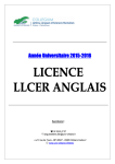
TRANSMISSION LINE PRESSURE CHECKS
c. Restricted orifice or incorrect orifice size.
d. Carbon build up at modulator vacuum fitting.
MINIMUM PSI
(Car coasting at 25 MPH)
P,N
L2
&D
1L
62
84
86
e. Pinched line.
MAXIMUM PSI
f. Grease in pipe (no or delayed upshift-cold).
(Stall check
ALTITUDE ABOVE
or J-loist check,
SEA LEVEL
see below)
OFt.
153
153
239
2,000
153
153
224
4,000
145
147
205
6,000
134
139
191
8,000
124
132
176
10,000
115
125
164
12,000
106
118
151
14,000
98
112
139
STALL CHECK
Stall engine at full throttle for no more than 10 seconds in Reverse, Drive,
L2 or L1 range.
HOIST CHECK
Run the engine at 1200 RPM with the modulator vacuum pipe dis-connected.
Lock the brakes at 0 MPH.
5B7C48
Figure 7C-8
www.TeamBuick.com
350-375B TRANSMISSION
EXHAUST-
DETENT EXHAUST-
|1.2| INTERMEDIATE
CLUTCH—.
- GOVERNOR
DETENT-
- LOW
(R.N.D.) REVERSE, NEUTRAL & DRIVE
MANUAL LOW
(2-3) DIRECT
CLUTCI-
MANUAL LOW | L) )
DETENT REGULATOR
REVERSE
23 ACCUMULATOR
AND LOW
(1-2) INTERMEDIATE
REVERSE
CLUTCH
DRAIN
MANUAL LOW
CONTROL VALVE
DETENT
DETENT VALVE
DRIVE
EXHAUST
1-2 SHIFT VALVE
LOW
LINE
(3-2) DETENT,
MODULATOR
EXHAUST
(3-2) DETENT, MODULATOR''
2-3 SHIFT VALVE
(MOD. S.V.)
MODULATOR
MODULATOR
THRU DETENT
(MOD. S.V.) MODULATOR
THRU DETENT VALVE
VALVE
DRIVE
EXHAUST
(1-2) INTERMEDIATE CLUTCH
MODULATOR
GOVERNC
INTERMEDIATE | L2
SUCTION
LIN..
MANUAL LOW (Li |
(HAUST
MANUAL VALVE
SUCTION
- (2-3 ) DIRECT CLUTCH
REVERSE
(R.N.D.) REVERSE, NEUTRAL AND DRIVE
MANUAL LOW ( Ll )
CONVERTER
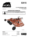
Figure 7C-9 - Identification of Oil Channels in Valve Body
NOTE:
24 BOLTHOLES MARKED WITH +
GOVERNOR-
(MOD.S.V.) MODULATOR ITHRU DETENT VALVEDRAIN-
DRIVE
DRAIN
(2-3) DIRECT CLUTCH
(2-3) DIRECT CLUTCH DRIVE
DRIVE
(1-2) INTERMEDIATE CLUTCH
SUCTION
(1-2) INTERMEDIATE CLUTCH
LINE
LINE
(2-3) DIRECT CLUTCH
(2-3) DIRECT CLUTCH
EXHAUST
LINE
(1-2) INTERMEDIATE CLUTCH
REVERSE, NEUTRAL & DRIVE
LINE
DETENT REGULATOR
LINE
EXHAUST
REVERSE
REVERSE, NEUTRAL & DRIVE
REVERSE
REVERSE, NEUTRAL A DRIVE
CONVERTER
REVERSE
MODUIATOR
DRIVE
(MOD.S.V.) MODULATOR
THRU DETENT VALVE
MANUAL LOW (Li )
MANUAL LOW) L1 )
EXHAUST
*USEDON 1971 PLATE
MODULATOR
(3-2) DETENT MODULATOR
MODULATOR
GOVERNOR
DETENT'
GOVERNORMANUAL LOW( Li ) •
LOW& REVERSEREVERSE-
DRAIN
(MOD.S.V.) MODULATOR
THRU DETENT VALVE
(3-2) DETENT MODULATOR
MANUAL LOW( L] )-
5B7C51
Figure 7C-10 - Valve Body Spacer Plate
7C- 13
7C- 14
www.TeamBuick.com
1975 BUICK SERVICE MANUAL
(2-3) DIRECT CLUTCH
(1 2) INTERMEDIATE CLUTCH
(1-2) INTERMEDIATE CLUTCH
REVERSE.
(R. N. D.)
NEUTRAL.
AND DRIVE.
(MOD S. V.) MODULATOR THRU
DETENT V,
LOW AND REVERSE
Figure 7C-11 - Identification of Oil Channels in Case Face
EXHAUST
DIRECT CLUTCH
■INTERMEDIATE CLUTCH
LIP SEAL DRAIN
FORWARD CLUTCH
COOLER IN
TO RADIATOR]
CONVERTER FEED
SUCTION
COOLER OUT
FROM RADIATOR
PUMP
PRESSURE
REVERSE
( DIRECT CLUTCH
OUTER)
INTERMEDIATE
CLUTCH
EXHAUST
EXHAUST
PUMP COVER AND STATOR SHAFT ASSEMBLY
4B7C53
Figure 7C-12 - Identification of Oil Channels in Pump Cover and Stator Shaft Face
www.TeamBuick.com
350-375B TRANSMISSION
7C- 15
EXHAUST
EXHAUST
PUMP
INTERMEDIATE
PRESSURE
CLUTCH
REVERSE
COOLER
BY-PASS
VALVE
COOLER OUT
FROM RADIATOR
COOLER IN
REVERSE
TO RADIATOR )
DIRECT CLUTCH
OUTER )
EXHAUST
CONVERTER FEED
PUMP LIP SEAL DRAIN
FORWARD CLUTCH
DIRECT CLUTCH
EXHAUST
PUMP BODY
4B7C54
Figure 7C-13 - Identification of Oil Channels in Pump Body Front Face
(5) PUMP BODY TO COVER
BOLT HOLES
INTERMEDIATE CLUTCH (APPLY)
BREATHER
COOLER OUT
DRAIN
FROM RADIATOR)
O\^~-COOLER IN
TO RADIATOR)
(8)PUMP
TO CASE
BOLT HOLES
EXHAUST
REVERSE ( DIRECT
CLUTCH OUTER
PUMP PRESSURE
FRONT PUMP COVER - (CASE FACE)
EXHAUST
PUMP SEAL DRAIN
INTERMEDIATE
CLUTCH
DIRECT CLUTCH
(INNER)
FORWARD CLUTCH
CONVERTER FEED
Figure 7C-14 - Identification of Oil Channels in Pump Cover Rear Face
7C-55
7C- 16
www.TeamBuick.com
1975 BUICK SERVICE MANUAL
CONVERTER FEED
SUCTION
FORWARD CLUTCH
PUMP PRESSURE
DIRECT CLUTCH (INNER)
REVERSE
INTERMEDIATE CLUTCH
(DIRECT CLUTCH OUTER)
DRAIN (4) CAST
OPEN PORTS
(8) PUMP TO CASE BOLT -
COOLER IN
TAPPED HOLES
(TO RADIATOR)
COOLER OUT
(FROM RADIATOR)
BREATHER
Figure 7C-15 - Case - Pump Identification of Oil Channels
MAINTENANCE AND ADJUSTMENTS
DETENT CABLE ADJUSTMENT SEE FIGURES
7C-16 AND7C-17
-ROUTE DETENT CABLE
UNDER THROTTLE CABLE
AS SHOWN
REMOVE PERFORATED SECTION
OF DASH INSULATOR IN THIS
AREA
RETAINER [El/
.
CABLE ASM
<a> apply 9985158 oil before asm.
[T|icaution1 care must be taken during
installation of these retainers that
the cable is not kinked or damaged.
\c] install cable thru throttle lever hole,
install retainer into throttle lever
hole being sure it is seated.
adjustment
throttle cable must be connected to
carburetor and throttle lever. depress
ACCELERATOR PEDAL TO WIDE OPEN THROTTLE
POSITION TO ADJUST DETENT CABLE.
ACCELERATOR PEDAL &
LEVER ASM ("A" SHOWN)
5B7C59
Figure 7C-1 6 - Transmission Detent Cable Adjustment - A and B Series
www.TeamBuick.com
350-375B TRANSMISSION
7C- 17
"SNAP LOCK"
DISENGAGED
POSITION
THROTTLE CONTROL
CABLE BRACKET
\a\ attach detent cable to transmission, clip,
encine bracket and carburetor.
L
2.
INSURE THAT "SNAP LOCK" BUTTON IS IN
DISENGAGED POSITION (CABLE SHOULD BE
FREE TO SLIDE THRU "SNAP LOCK").
OPEN CARBURETOR LEVER TO WIDE OPEN
THROTTLE STOP.
3.
PUSH "SNAP LOCK" TO ENGAGE POSITION
("SNAP LOCK" FLUSH WITH REST OF CABLE
FITTING).
> APPLY OIL BEFORE ASSEMBLY.
[d] fitting must have locking tangs expanded
AND LOCKED IN BRACKET ATTACHING HOLE.
5B7C17
Figure 7C-17 Detent Cable Adjustment H and X Series
REMOVAL OF PROPELLER SHAFT YOKE SEAL
(375B ONLY), SPEEDOMETER DRIVE GEAR,
Removal and Installation of Speedometer Drive
Gear
Removal
AND GOVERNOR
1. Depress retaining clip and remove from output shaft.
Removal of Propeller Shaft Yoke Seal (375B Only)
Remove propeller shaft yoke seal, using Tool J- 23103 and
screwdriver. See Figure 7C-18.
Installation
1. Align slot in speedometer drive gear with retaining clip
and install. See Figure 7C-19.
SPEEDOMETER
DRIVE
GEAR
7C-60
Figure 7C-18 - 375B Transmission
Figure 7C-19
7C- 18
www.TeamBuick.com
1975 BUICK SERVICE MANUAL
Removal of Governor
1. Remove governor cover retainer wire with a screw
driver. See Figure 7C-20.
7C-64
Figure 7C-22
GOVERNOR COVER
RETAINER WIRE
Check governor bore and governor sleeve for scoring.
Refer to 400 section for governor overhaul procedlures.
7C-236
Figure 7C-2O
MAINTENANCE
Draining Oil Pan and Replacing Filter Assembly
With transmission in the car,
2. Remove governor cover and "O" ring seal from case.
Aid removal of cover with screwdriver. Use extreme care
not to damage cover. If cover is damaged it must be re
placed.
Remove "O" ring seal from governor cover, and replace.
See Figure 7C-21.
1. Raise car on hoist or place on jack stands, and provide
container to collect draining fluid. Care should be taken
if transmission is hot.
2. Remove oil pan and gasket. Discard gasket.
3. Drain fluid from oil pan. Clean pan with solvent and
dry thoroughly with clean compressed air.
4. Remove filter assembly and gasket.
5. Install new oil filter to valve body gasket on filter.
Install new filter assembly.
GOVERNOR COVER
6. Install new gasket on oil pan and install pan. Tighten
attaching bolts to 13 lb. ft.
7. Lower car and add 3 pints of transmission fluid through
filler tube.
8. With manual control lever in Park position, start en
gine. DO NOT RACE ENGINE. Move manual control
lever through each range.
9. Immediately check fluid level with selector lever in
Park, engine running, and vehicle on LEVEL surface.
GOVERNOR COVER
TO CASE UO" RING
SEAL
10. Add additional fluid to bring level to l/4/; below the
"ADD" mark on the dipstick. Do not overfill.
Turbo Hydra-Matic 350-375B Towing Instructions
Figure 7C-21
If a Buick equipped with Turbo Hydra-Matic 350-375B
transmission must be towed, the following precautions
must be observed:
3. Withdraw governor assembly from case. See Figure
The car may be towed safely on its rear wheels with the
shift lever in neutral position at speeds of 35 miles per
7C-22.
hour or less under most conditions.
www.TeamBuick.com
350-375B TRANSMISSION
However, the drive shaft must be disconnected or the car
towed on its front wheels if tow speeds in excess of 35 mph
7C- 19
are necessary.
Car must be towed for extended distances (over 50 miles)
or, Transmission is not operating properly.
If car is towed on its front wheels, the steering wheel
should be secured to keep the front wheels in a straight-
ahead position.
Rocking Car
If it becomes necessary to rock the car to free it from sand,
mud or snow, move the selector lever from "D" to "R"
in a repeat pattern while simultaneously applying moder
ate pressure to the accelerator. Do not race engine. Avoid
spinning wheels when trying to free the car.
REMOVAL OF OIL PAN, OIL FILTER, AND VALVE
BODY WITH TRANSMISSION REMOVED
Removal of Oil Pan
OIL PUMP FILTER
TO VALVE BODY
4B 7C67
Figure 7C-25
body. Remove valve body to case attaching bolts. See
1. Remove (13) oil pan attaching screw and washer assem
blies, oil pan, and gasket. See Figure 7C- 23.
Figure 7C-26.
DETENT SPRING AND
ROLLER ASSEMBLY
DETENT CONTROL
VALVE LINK
Figure 7C-23
Removal of Oil Filter
1. Remove two (2) filter assembly to valve body attaching
screws. See Figure 7C-24.
7C-69
Figure 7C-26
manual valve link from range selector inner lever. Remove
detent control valve link from detent actuating lever.
3. Remove valve body to spacer plate gasket. See Figure
7C-27.
4. Remove spacer support plate bolts. Remove spacer sup
port plate. See Figure 7C-28.
Figure 7C-24
2. Remove filter assembly and gasket from valve body. See
Figure 7C-25.
Removal of Valve Body
1. Remove detent roller and spring assembly from valve
2. Remove valve body from case while carefully guiding
5. Remove valve body spacer plate and valve body spacer
plate to case gasket. See Figure 7C-29. Be sure to note
position of the four (4) plastic check balls so they are
assembled correctly.
MAJOR REPAIR
TRANSMISSION ASSEMBLY - REMOVAL AND
INSTALLATION
Removal
1. Place transmission in neutral, release parking brake,
and disconnect the battery.
7C-20
www.TeamBuick.com
1975 BUICK SERVICE MANUAL
VALVE BODY SPACER PLATE
VALVE BODY
SPACER PLATE
VALVE BODY SPACER
PLATE TO CASE GASKET
VALVE BODY TO
SPACER PLATE GASKET
Figure 7C-29
Figure 7C-27
8. Support engine at oil pan.
9. Assemble transmission to suitable transmission jack.
10. Remove transmission mounting pad to crossmember
nut.
11. Raise transmission and remove crossmember to frame
rail bolts. Remove crossmember.
12. Lower transmission enough to remove cooler lines,
speedometer cable, shift linkage, catalytic converter
bracket on A B Series, and the filler pipe.
13. Remove flywheel cover pan.
14. Mark flywheel and converter for reassembly in the
same position, and remove three converter to flywheel
bolts.
15. Remove transmission case to engine block bolts.
16. Slide transmission rearward and lower it away from
car using tool J-21366 to hold converter in place.
SPACER SUPPORT PLATE
7C-71
Figure 7C-28
2. Disconnect detent cable from accelerator lever or car
buretor assembly.
3. Raise car and provide support for front and rear.
(NOTE: On some models the exhaust crossover pipe may
have to be removed.)
Installation
The installation of the transmission is the reverse of re
moval except for the following reminder steps.
1. Connect converter and flywheel in original position.
2. Torque engine to transmission case bolts to 35 lb. ft.
3. Torque flywheel to converter bolts to 30 lb. ft.
4. Fill transmission with fluid as described in fluid
recommendations O.Section Maintenance.
4. Remove the propeller shaft. (H Series remove upper
torque arm transmission end).
5. Remove vacuum line from vacuum modulator.
6. Being careful not to bend the detent cable remove
plastic guide straight up from bracket and slide detent
cable out through slot.
7. Remove detent cable from detent valve link. Do not
bend cable.
PRELIMINARY INSTRUCTIONS
1. Before starting disassembly of the transmission it
should be thoroughly cleaned externally to avoid getting
dirt inside.
2. Place transmission on a CLEAN work bench and use
CLEAN tools during disassembly. Provide clean storage
350-375B TRANSMISSION
www.TeamBuick.com
7C- 21
space for parts and units removed from transmission.
3. The transmission contains parts which are ground and
highly polished, therefore, parts should be kept separated
REMOVAL OF CONVERTER HOLDING TOOL
4. When disassembling transmission carefully inspect all
gaskets at times of removal. The imprint of parts on both
sides of an old gasket will show whether a good seal was
obtained. A poor imprint indicates a possible source of oil
leakage due to gasket condition, looseness of bolts, or
Removal of Converter
J-21366, CONVERTER, VACUUM MODULATOR
to avoid nicking and burring surfaces.
uneven surfaces of parts.
5. None of the parts require forcing when disassembling
or assembling transmission. Use a rawhide or plastic mal
let to separate tight fitting cases - do not use a hard ham
1. Assemble transmission in Fixture J-8763. Do not over-
tighten. See Figure 7C-32.
2. Remove converter Holding Tool J-21366. See Figure
7C-33.
*
3. With transmission in Holding Fixture J-8763, remove
torque converter assembly. See Figure 7C-35.
TORQUE
mer.
CONVERTER
ASSEMBLY
7C-79
Figure 7C-35
HOLDING FIXTURE
J-8763
7C-76
Removal of Vacuum Modulator
Figure 7C-32
1. Remove modulator assembly attaching bolt and re
tainer. See Figure 7C-36.
VACUUM MODULATOR
CONVERTER HOLDING
TOOL J-21366
VACUUM MODULATOR RETAINER
7C-80
Figure 7C-33
Figure 7C-36
7C- 22
1975 BUICK SERVICE MANUAL
www.TeamBuick.com
2. Remove vacuum modulator assembly "O" ring seal and
modulator valve from case. See Figure 7C-37.
VACUUM
MODULATOR VALVE
EXTENSION
HOUSING
TO CASE
OIL SEAL
7C-83
Figure 7C-39
VACUUM MODULATOR
7C-81
Removal of Extension Housing Lip Seal
1. Remove extension housing lip seal using screwdriver.
See Figure 7C-40.
Figure 7C-37
REMOVAL OF EXTENSION HOUSING,
SCREWDRIVER
LIP SEAL AND BUSHING
Removal of Extension Housing
1. Remove bolt retainer and speedometer driven gear from
side of extension housing and remove four (4) extension
housing to case attaching bolts. See Figure 7C-38.
(NOTE: Remove catalytic converter studs on A B Series.)
EXTENSION
HOUSING
LIP SEAL
7C-84
Figure 7C-40
Removal of Extension Housing Bushing
1. Remove extension housing bushing using screwdriver
to collapse bushing. See Figure 7C-41.
7C-82
Figure 7C-38
INSTALL EXTENSION HOUSING BUSHING AND
LIP SEAL
Removal of Extension Housing Seal
Installation of Extension Housing Bushing
1. Remove extension housing to case oil seal. See Figure
7C-39.
J-8092 and Bushing Tool J-21424-1. See Figure 7C-42.
1. Install extension housing bushing using Drive Handle
350-375B TRANSMISSION
www.TeamBuick.com
7C- 23
NOTCH IN
EXTENSION
HOUSING
J-21426
EXTENSION
EXTENSION
HOUSING
HOUSING
LIP SEAL
BUSHING
7C-85
Figure 7C-41
7C-87
Figure 7C-43
OIL PUMP PRESSURE SCREEN !
EXTENSION
HOUSING
OIL PUMP PRESSURE HOLE
7O86
Figure 7C-42
Figure 7C-44
Installation of Extension Housing Lip Seal
1. Install extension housing lip seal using Installer J-
21426. See Figure 7C-43.
REMOVAL OF OIL PUMP SCREEN, GOVERNOR
SCREENS, AND CHECK BALLS
Removal of Pressure Screen
1. Remove oil pump pressure screen from oil pump pres
sure hole in case, and clean. See Figure 7C-44.
2. Remove governor screens from case and clean. See
Figure 7C-45.
Figure 7C-45
7C- 24
1975 BUICK SERVICE MANUAL
4. Remove manual shaft from case. Remove range selector
www.TeamBuick.com
inner lever and parking pawl actuating rod.
Removal of Check Balls
1. Remove four check balls from case face.
REMOVAL OF MANUAL SHAFT, INNER, LEVER,
PARKING PAWL, AND INTERMEDIATE SERVO
PISTON
5. Remove manual shaft to case lip seal, if necessary. See
Figure 7C-48.
6. Remove parking lock bracket.
7. Remove parking pawl shaft retaining plug stake marks.
Remove retaining plug, parking pawl shaft, parking pawl,
and disengaging spring. See Figure 7C-49.
Removal of Range Selector Inner Lever
1. Remove manual control valve link retainer from range
selector inner lever.
2. Remove manual shaft to case retainer with screwdriver.
See Figure 7C-47.
3. Remove jam nut holding range selector inner lever to
manual shaft.
MANUAL SHAFT TO
CASE RETAINER
DISENGAGING
L1 SPRING
j PARKING PAWL SHAFT
[RETAINING PLUG
7C-96
Figure 7C-49
B. Removal of Intermediate Servo Piston
1. Remove intermediate servo piston, washer, spring seat,
and apply pin. See Figure 7C-50.
Figure 7C-47
2. If the piston seal needs replacing, the piston assembly
will have to be replaced. This is due to a plastic grooved
piston that is not serviceable. (Piston and Seal are one
assembly).
^INTERMEDIATE
SERVO PISTON
MANUAL SHAFT TO
CASE LIP SEAL
WASHER
SPRING SEAT
SPRING
Figure 7C-48
Figure 7C-5O
www.TeamBuick.com
REMOVAL OF PUMP ASSEMBLY, CUSHION
350-375B TRANSMISSION
SPRING, INTERMEDIATE CLUTCH PLATES,
AND OVERRUN BRAKE BAND
Removal of Oil Pump Assembly
1. Remove eight (8) pump attaching bolts with washer
type seals. Discard washer type seals.
7C- 25
If the surface is smooth and an even color smear is in
dicated, the plates should be reused. If severe heat spot
discoloration or surface scuffing is indicated, the plates
must be replaced.
INTERMEDIATE CLUTCH
2. Install two (2) threaded slide hammers J-7004 into
threaded holes in pump body. Tighten jam nuts and
remove pump assembly from case. See Figure 7C-53.
Figure 7C-54
4. Remove intermediate clutch pressure plate.
5. Remove intermediate overrun brake band. See Figure
7C-55.
Figure 7C-53
3. Remove pump assembly to case gasket and discard.
Removal of Intermediate Clutch Cushion Spring,
Intermediate Clutch Plates and Intermediate
Overrun Brake Band
1. Remove intermediate clutch cushion spring.
2. Remove three (3) or (2) intermediate clutch faced plates
and three (3) or (2) steel separator plates. See Figure
7C-54.
3. Inspect condition of the lined and steel plates. Do not
diagnose a lined drive plate by color.
A. Dry lined plates with compressed air and inspect the
lined surfaces for:
1. Pitting and flaking
INTERMEDIATE OVERRUN
BRAKE BAND
2. Wear
3. Glazing
4. Cracking
Figure 7C-55
5. Charring
REMOVAL OF DIRECT AND FORWARD CLUTCH
ASSEMBLIES, INPUT RING GEAR, AND
6. Chips or metal particles imbedded in lining
OUTPUT CARRIER
If a lined drive plate exhibits any of the above conditions,
Removal of Direct and Forward Clutch Assemblies
B. Wipe steel plates dry and check for heat discoloration.
case. See Figure 7C-56.
replacement is required.
1. Remove direct and forward clutch assemblies from
7C- 26
www.TeamBuick.com
1975 BUICK SERVICE MANUAL
J-8092
J-23062-5
INPUT RING
GEAR
7C-111
FORWARD AND DIRECT
CLUTCH ASSEMBLIES
Figure 7C-58
Figure 7C-56
Removal of Output Carrier Assembly
1. Remove input ring gear to output carrier needle thrust
Removal of Input Ring Gear
1. Remove forward clutch housing to input ring gear front
thrust washer. Inspect for excessive wear or scoring.
bearing.
2. Remove output carrier to output shaft snap ring and
discard. See Figure 7C-59.
2. Remove input ring gear. See Figure 7C-57.
Figure 7C-59
3. Remove output carrier assembly.
Figure 7C-57
3. Inspect bushing for wear or galling. If replacement is
necessary proceed as follows:
a. Thread Tool J-23062-5 on Drive Handle J-8092, and
remove bushing from ring gear. See Figure 7C-58.
b. Using Tool J-23062-5, press in new bushing .050" to
.060" from inner surface of hub. See Figure 7C-58.
REMOVAL OF SUN GEAR DRIVE SHELL, LOW
AND REVERSE CLUTCH SUPPORT ASSEMBLY,
LOW AND REVERSE CLUTCH PLATES, AND
REACTION CARRIER
Removal of Sun Gear Drive Shell Assembly
1. Remove sun gear drive shell assembly. See Figure 7C60.
www.TeamBuick.com
350-375B TRANSMISSION
7C- 27
msmmm
LOW AND REVERSE
Figure 7C-60
Removal of Low and Reverse Clutch Support
CLUTCH PACK
5B7C119
Figure 7C-62
Assembly
1. Remove low and reverse roller clutch support to case
Removal of Reaction Carrier Assembly
2. Grasp output shaft and pull up until low and reverse
roller clutch and support assembly clear low and reverse
clutch support retainer spring and remove support assem
gear and shaft assembly. See Figure 7C-63.
retaining ring. See Figure 7C-61.
1. Remove reaction carrier assembly from output ring
bly.
3. Remove low and reverse clutch support retainer spring.
See Figure 7C-61.
retainer spri img
transmission" case
NOTE:
FOR ILLUSTRATION PURPOSES T*L
TRANSMISSION HAS BEEN CUT
IN TWO
LOW AND REVERSE, CLUTCH SUPPORT
LOW AND REVERSE ROLLER CLUTCH
_SUPPORT TO CASE RETAINER SPRING
__
TRANSMISSION
LOW AND REVERSE ROLLER
CASE RETAINING RING
TO
CASE
CLUTCH
Figure 7C-63
Figure 7C-61
Removal of Low and Reverse Clutch Plates
1. Remove five (5) or (4) low and reverse clutch faced
plates and five (5) or (4) steel separator plates. See Figure
7C-62.
2. Inspect reaction carrier bushing for wear or galling. If
replacement is necessary proceed as follows:
a. Thread tool J-23062-3 on Drive Handle J-8092 and
remove bushing. See Figure 7C64.
b. Using Tool J-23062-3 press in new bushing flush to
.010/; from inner surface of hub. See Figure 7C-64.
7C- 28
www.TeamBuick.com
1975 BUICK SERVICE MANUAL
OUTPUT RING GEAR
J-8092
REACTION
CARRIER
J-23062-3
5B7C124
7C-121
Figure 7C-64
Figure 7C-66
4. Remove output ring gear to case needle bearing. See
Figure 7C-67.
REMOVAL OF OUTPUT RING GEAR AND SHAFT
ASSEMBLY, AND OUTPUT RING GEAR TO
CASE NEEDLE BEARING ASSEMBLY
OUTPUT RING GEAR
TO CASE NEEDLE
BEARING
Removal of Output Ring Gear and Shaft Assembly
1. Remove output ring gear and shaft assembly from case.
See Figure 7C-65.
Figure 7C-67
OUTPUT RING GEAR
AND OUTPUT SHAFT
ASSEMBLY
OUTPUT RING GEAR
OUTPUT SHARX ,
Figure 7C-65
2. Remove reaction carrier to output ring gear needle
thrust bearing.
3. Remove output ring gear to output shaft snap ring and
discard. Remove output ring gear from output shaft. See
Figure 7C-66.
Figure 7C-69
www.TeamBuick.com
350-375B TRANSMISSION
5. Inspect output shaft bushing for wear or galling. If
replacement is necessary proceed as follows:
a. Assemble J-9534-01 into Adapter J-2619-4 and assem
ble to Slide Hammer J-2619. Thread assembly into bush
ing. Clamp slide hammer into vise, grasp output shaft and
7C- 29
2. Remove low and reverse clutch piston assembly. Aid
removal with the use of compressed air in passage shown.
See Figure 7C-73.
remove bushing. See Figure 7C-69.
b. Using Tool J-23062-7, assembled into Drive Handle
J-8092, press in new bushing .140" below end surface of
shaft. See Figure 7C-70.
APPLY AIR PRESSURE
HERETO REMOVE LOW
& REVERSE CLUTCH PISTON
J-8092
DRIVE HANDLE
J-23062-7
OUTPUT
Figure 7C-73
RING
GEAR
7C-128
Figure 7C-7O
REMOVAL OF LOW AND REVERSE CLUTCH
PISTON, AND CASE BUSHING
Removal of Low and Reverse Clutch Piston Seals
1. Remove low and reverse clutch piston outer seal.
2. Remove low and reverse clutch piston center and inner
seal. See Figure 7C-74.
Removal of Low and Reverse Clutch Piston
1. Using Tool J-21420-1 compress low and reverse clutch
piston spring retainer and remove piston retaining ring,
and spring retainer with springs. See Figure 7C-71.
REVERSE CLUTCH PISTON
| INNER SEAL
7C-133
LOW & REVERSE
Figure 7C-74
CLUTCH PISTON
Removal and Installation of Case Bushing
Figure 7C-71
1. Inspect case bushing for nicks, scoring or excessive
wear. If damaged, remove as follows: Assemble Tool J23062-1 on Drive Handle J-8092 and remove bushing. See
Figure 7C-75.
7C- 30
1-2 accumulator cover and remove retaining ring. See
www.TeamBuick.com
1975 BUICK SERVICE MANUAL
Figure 7C-77.
INTERMEDIATE
CLUTCH ACCUMULATOR
COVER COMPRESSOR
J-23069
J-8092
507C137
DRIVE
HANDLE
Figure 7C-75
Figure 7C-77
2. Using Tool J-23062-1 and Drive Handle J-8092, press
bushing to .195" below chamfered edge of case. Make
certain split on bushing is opposite notch in case. See
2. Remove intermediate clutch 1-2 accumulator piston
cover and "O" ring seal from case. See Figure 7C-78.
Figure 7C-76.
J-8092
DRIVE
HANDLE
Figure 7C-78 Intermediate Clutch 1-2 Accumulator
7C-135
3. Remove intermediate clutch 1-2 accumulator piston
spring. See Figure 7C-78.
Figure 7C-76
REMOVAL AND INSTALLATION OF
INTERMEDIATE CLUTCH 1-2 ACCUMULATOR Re
moval and installation of intermediate clutch 1-2 ac
cumulator can be done without removal of transmission
from car.
4. Remove intermediate clutch 1-2 accumulator piston
assembly. Inspect the inner and outer teflon oil seal rings
for wearing or scoring DO NOT REMOVE THESE
TWO RINGS UNLESS THEY ARE DAMAGED. If
replacement of one or the other of the two rings is neces
sary. The piston assembly will have to be replaced. See
Figure 7C-78. (Piston and Seal are one assembly).
Installation of Intermediate Clutch 1-2
Removal of Intermediate Clutch 1-2 Accumulator
Accumulator Piston
Piston
1. Install intermediate clutch 1-2 accumulator piston as
sembly. See Figure 7C-78.
1. Install Tool J-23069 to compress intermediate clutch
www.TeamBuick.com
2. Install intermediate clutch 1-2 accumulator piston
spring. See Figure 7C-78.
3. Place "0" ring seal on intermediate clutch 1-2 ac
cumulator piston cover, and install cover into case. See
Figure 7C-78.
4. Install J-23069 tool and compress intermediate clutch
1-2 accumulator cover and install retaining ring. See Fig
ure 7C-77.
350-375B TRANSMISSION
7C- 31
DISASSEMBLY AND REASSEMBLY OF OIL PUMP
ASSEMBLY
Disassembly of Oil Pump Assembly
1. Place assembly through hole in bench. Remove five (5)
pump cover to body attaching bolts. See Figure 7C-79.
2. Remove intermediate clutch return spring seat retainer
with springs and the intermediate clutch piston assembly.
See Figure 7C-8O.
3. Remove intermediate clutch piston inner and outer
seals. See Figure 7C-81.
INTERMEDIATE
CLUTCH SPRING
SEAT RETAINER
INTERMEDIATE CLUTCH,
PISTON OUTERSEAL
INTERMEDIATE
CLUTCH PISTON
INNER SEAL
PUMP COVER TO
PUMP BODY BOLTS (5)
5B7C141
Figure 7C-79
4B7C143
Figure 7C-81
_PUMP TO CONVERTER
HUB LIP SEAL
SQUARE CUT "O" RING SEAL
PUMP COVER TO
DIRECT CLUTCH
DRUM NEEDLE
THRUST BEARING
INTERMEDIATE CLUTCH
PISTON ASSEMBLY
FORWARD CLUTCH
TO PUMP HUB TEFLON
TYPE RINGS (2)
DIRECTCLUTCH TO PUMP
-DRIVE GEAR
-PUMP BODY ASSEMBLY
HUB HOOK TYPE OIL
SEAL RINGS (3)
PUMP COVER AND STATOR_
SHAFT ASSEMBLY
PUMP COVER TO PUMP BODY
ATTACHING BOLTS (5)
Figure 7C-80 Oil Pump Assembly
7C- 32
www.TeamBuick.com
J-23134 and force by-pass valve seat, check ball, and
1975 BUICK SERVICE MANUAL
spring from pump body. See Figure 7C-84.
4. Remove three (3) direct clutch to pump hub hook type
oil rings. Remove pump cover to direct clutch drum nee
dle thrust bearing. Inspect the two (2) forward clutch to
pump hub teflon oil seal rings, but do not remove them
unless they are damaged. If replacement is necessary, use
two metal hook type service replacement rings. See Figure
7C-8O.
5. Remove pump cover and stator shaft assembly from
pump body. See Figure 7C-82.
PUMP BODY
PUMP COVER AND
STATOR SHAFT
ASSEMBLY
COOLER BY-PASS VALVEV-J-23134
PUMP BODY
7C-148
Figure 7C-84
8. Remove pump outside diameter to case square cut "O"
ring seal and discard. See Figure 7C-86.
7C-145
Figure 7C-82
6. Remove pump drive gear and driven gear from pump
body. Inspect pump gears and cover for wear or scoring.
See Figure 7C-83.
PUMP O. D. TO CASE
(SQUARE CUT) "O" RING
DRIVEN GEAR
9. Remove pump body to converter hub lip seal, if neces
sary and discard. See Figure 7C-87.
DRIVE GEAR
7C-147
Figure 7C-83
7. Fill cooler by-pass passage with grease and insert Tool
10. Place pump on wood blocks so surface finish is not
damaged and install pump to converter hub lip seal using
Seal Driver J-21359. See Figure 7C-88. Make certain lip
seal is not turn or nicked.
11. Check oil pump bushing for nicks severe scoring or
wear. If bushing replacement is necessary remove as fol
lows: support pump on wood blocks. Use Tool J-21465-17
and Drive Handle J-8092 press bushing out of pump body.
www.TeamBuick.com
350-375B TRANSMISSION
PUMP TO CONVERTER
7C- 33
J-8092
HUB LIP SEAL
DRIVE
HANDLE
PUMP BODY
WOOD BLOCKS
7C-150
Figure 7C-87
Figure 7C-89
J-21359
J-21465-15
J-2619-4
PUMP TO
ADAPTER
CONVERTER
HUB LIP SEAL
PUMP BODY
WOOD BLOCKS
BODY PUMP
7C-151
PUMP COVER
AND STATOR
Figure 7C-88
To install new oil pump bushing use Tool J-21465-17 and
Drive Handle J-8092 and press bushing into pump body
from gear pocket face until it is flush to .010" below
opposite face. (Front Pump Seal Side). See Figure 7C-89.
12. Check front stator shaft bushing for nicks, severe scor
ing or wear. If bushing replacement is necessary remove
as follows: Assemble bushing remover J-21465-15 to
adapter J-2619-4. Assemble this assembly to Slide Ham
mer J-2619. Clamp Slide Hammer into vise. Grasp stator
shaft and remove bushing. See Figure 7C- 90.
13. Install front stator shaft bushing as follows: Support
pump assembly on J-21424-7 before installing bushing.
Install bushing into the front end of stator shaft. Using
Installer J-21424-7 and Drive Handle J-8092 tap bushing
into shaft to 1/4 inch below top of stator shaft. See Figure
7C-91. Extreme care must be taken so bushing is not
driven past shoulder.
SHAFT ASSEMBLY
7C-153
Figure 7C-9O
14. If replacement of lower rear stator shaft bushing is
required, proceed as follows: Thread Tool J-21465-15 into
stator shaft lower rear bushing. Thread Slide Hammer
J-2619 into remover. Clamp slide hammer into vise. Grasp
stator shaft and remove bushing. See Figure 7C-92. If
upper rear stator shaft bushing is required, repeat above
procedure.
Using Tool J-23062-2 press upper rear stator shaft bush
ing 1-1/32 inch below top surface of oil pump delivery
sleeve. See Figure 7C-93.
Using Tool J-23062-2 press lower rear stator shaft bushing
flush to .010" below chamfer on oil pump delivery sleeve.
7C- 34
www.TeamBuick.com
1975 BUICK SERVICE MANUAL
J-21465
J-8092
ADAPTER
DRIVE
HANDLE
J-21424-7
PUMP COVER
PUMP
AND STATOR
BODY
SHAFT ASSEMBLY
J-23062-'
PUMP COVER
AND STATOR
SHAFT ASSEMBLY
5B7C156
7C-154
Figure 7C-93
Figure 7C-91
ADAPTER
1.4
SLIDE HAAAMER
PUMP COVER
AND STATOR
SHAFT ASSEMBLY
J-23112
7C-158
5B7C155
Figure 7C-94
Figure 7C-92
Reassembly of Oil Pump Assembly
1. Install pump drive gear and driven gear.
Drive gear has ofF-set tangs, assemble with tang face up to
prevent damage to converter. See Figure 7C-83.
2. Install cooler by-pass spring, check ball and seat. Using
Tool J-23112, press seat into bore until top of seat is flush
with face of pump body. See Figure 7C- 94.
3. Assemble pump cover to pump body. See Figure 7C-82.
4. Install intermediate clutch piston inner seal and outer
seal. See Figure 7C-81.
5. Install intermediate clutch piston assembly into pump
cover with the aid of a piece of .020" music wire crimped
into copper tubing.
6. Install spring retainer and install five (5) attaching
bolts, finger tight. See Figures 7C-80 and 7C-79.
7. Place pump aligning strap, J-21368 over pump body
and cover and tighten.
8. Tighten attaching bolts. Torque to 18 lb.ft.
9. Install pump outside diameter to case (square cut) "O"
ring seal. See Figure 7C-86. Use new square cut "O" ring
seal.
10. Install three (3) direct clutch to pump hub hook type
oil seal rings. Inspect two (2) forward clutch to pump hub
teflon oil seal rings, for service if rings require replacement
use hook type cast iron rings. See Figure 7C-80.
11. Check three (3) pump cover hub lube holes. Make
certain they are not restricted. See Figure 7C-95.
www.TeamBuick.com
350-375B TRANSMISSION
7C- 35
INTERMEDIATE OVERRUN
ROLLER OUTER RACE
5B7C160
Figure 7C-95
7C-162
Figure 7C-97
DISASSEMBLY AND REASSEMBLY OF DIRECT
CLUTCH
(NOTE: Refer to specifications in rear of this section to
determine the required amount of lined and steel clutch
plates to use with specific transmission model and engine
combination. When replacing piston assembly specific
part number must be used.)
3. Remove intermediate overrun roller clutch assembly
See Figure 7C-98.
Intermediate overrun
roller clutch assembly
Disassembly of Direct Clutch
1. Remove intermediate overrun clutch front retainer ring
and retainer. See Figure 7C-96.
RETAINING RING
7C-163
Figure 7C-98
4. Remove direct clutch drum to forward clutch housing
needle roller bearing. See Figure 7C-99.
DIRECT CLUTCH ASSEMBLY
7(>161
5. Remove direct clutch pressure plate to clutch drum
retaining ring and pressure plate. See Figure 7C- 100.
6. Remove lined and steel plates from direct clutch hous
ing. See Figure 7C-101.
Figure 7C-96
2. Remove intermediate clutch overrun outer race. See
Figure 7C-97.
7. Inspect condition of lined and steel plates.
diagnose a lined drive plate by color.
Do not
A. Dry lined plates with compressed air and inspect the
lined surfaces for:
7C- 36
www.TeamBuick.com
1975 BUICK SERVICE MANUAL
STEEL
PLATES
DIRECT CLUTCH DRUM TO
FORWARD CLUTCH HOUSING
NEEDLE ROLLER BEARING
LINED PLATES
4B7C166
Figure 7C-101
Figure 7C-99
DIRECT
J-2590-3
CLUTCH
J-2590-5
HOUSING
r—RETAINING RING
-PRESSURE PLATE
.DIRECT CLUTCH DRUM
RETAINING
SPRING
RING
RETAINER
SNAP RING
PLIERS
7C-168
Figure 7C-1O3
7C-165
DIRECT CLUTCH PISTON RETURN
SPRINGS (17)
Figure 7C-100
1. Pitting and flaking
2. Wear
3. Glazing
4. Cracking
5. Charring
6. Chips or metal particles imbedded in lining
If a lined drive plate exhibits any of the above conditions,
replacement is required.
B. Wipe steel plates dry and check for heat discoloration.
If the surface is smooth and an even color smear is in
dicated, the plates should be reused. If severe heat spot
discoloration or surface scuffing is indicated, the plates
must be replaced.
DIRECT CLUTCH
PISTON
7C-169
Figure 7C-1O4
www.TeamBuick.com
350-375B TRANSMISSION
8. Remove direct clutch piston return spring seat retaining
ring and spring seat by using Tools J- 2590-3, J-2590-5,
and snap ring pliers. See Figure 7C- 103.
9. Remove spring retainer, springs and piston. See Figure
7C- 37
and remove bushing using care not to score inner surface
of direct clutch drum. See Figure 7C- 107.
7C-104.
10. Inspect the return springs. Evidence of extreme heat
or burning in the area of the clutch may have caused the
springs to take a heat set and would justify replacement
of the springs.
11. Remove direct clutch piston inner and outer seals. See
CAPE CHISEL
BUSHING
Figure 7C-105.
OUTER SEAL
DIRECT CLUTCH DRUM
7C-172
Figure 7C-1O7
14. Install direct clutch bushing using Tool J- 23062-4,
Drive Handle J-8092, and install .010" below slot in re
tainer hub. See Figure 7C-108.
INNER SEAL
7C-170
Figure 7C-1O5
J-8092
12. Remove direct clutch piston center seal. See Figure
7C-106.
J-23062-4
DIRECT
DIRECT
CLUTCH
CLUTCH
DRUM
DRUM
7C-173
Figure 7C-1O8
CLUTCH PISTON
Reassembly of Direct Clutch
CENTER SEAL
7C-171
1. Install direct clutch piston outer seal and inner seal. See
Figure 7C-1O5.
Figure 7C-1O6
2. Install direct clutch piston center seal. See Figure 7C-
13. If bushing replacement is necessary, use a Cape Chisel
3. Install the direct clutch piston into housing with the aid
106.
7C- 38
www.TeamBuick.com
1975 BUICK SERVICE MANUAL
STEEL PLATES
of a piece of .020" music wire crimped into copper tubing.
See Figure 7C-109.
.020" MUSIC WIRE CRIMPED
INTO COPPER TUBING
PISTON
7C-175
Figure 7C-110
DIRECT CLUTCH HOUSING
7C-174
Roller clutch assembly must be assembled with four (4)
holes up (toward front of transmission).
8. Install intermediate clutch overrun outer race. See Fig
Figure 7C-109
ure 7C-112.
4. Install spring retainer and springs. Compress spring
retainer and install retaining ring, using Tools J-2590-3
and J- 2590-5. See Figure 7C-103.
When the intermediate overrun clutch outer race is in
stalled, it should free wheel in the counterclockwise direc
5. Lubricate with transmission fluid and install faced
plates and steel separator plates starting with a steel plate
and alternating steel and faced. See Figure 7C-110.
9. Install intermediate overrun clutch retainer, and retain
6. Install direct clutch pressure plate and retaining ring.
See Figure 7C-100.
DISASSEMBLY AND REASSEMBLY OF
7. Install intermediate overrun roller clutch assembly. See
Figure 7C-112.
(NOTE: Refer to specifications in rear of this section to
determine the required amount of lined and steel clutch
tion only.
ing ring. See Figure 7C-112.
FORWARD CLUTCH ASSEMBLY
•DIRECTCLUTCH DRUM
STEEL SEPARATOR
PLATES
DIRECT CLUTCH
PISTON ASSEMBLY
RETAINING RING—1
FACED PLATE
DIRECTCLUTCH PRESSURE PLATE
RETAINING RING
Figure 7C-111 - Direct Clutch Assembly - Exploded View
7C-178
www.TeamBuick.com
350-375B TRANSMISSION
7C- 39
A. Dry lined plates with compressed air and inspect the
lined surfaces for:
CAUTION: IF ROLLER FALLS OUT DURING ASSEMBLY OPERATION —REINSTALL ROLLER
FROM INSIDE TO OUTSIDE CAGE DIRECTION TO AVOID BENDING SPRING
INTERMEDIATE CLUTCH
OVERRUN OUTER RACE
(LOCKS ON CLOCKWISE ROTATION)
1. Pitting and flaking
2. Wear
3. Glazing
r"
4. Cracking
5. Charring
6. Chips or metal particles imbedded in lining
If a lined drive plate exhibits any of the above conditions,
replacement is required.
B. Wipe steel plates dry and check for heat discoloration.
ROLLER CLUTCH ASSEMBLY
DIRECT CLUTCH DRUM
AND INTERMEDIATE CLUTCH
OVERRUN INNER CAM
POSITION WITH 4 HOLES
TOWARD FRONT OF TRANSMISSION
4B7C176
Figure 7C-112 - Intermediate Overrun Roller Clutch
CUSHION SPRING
Assembly
plates to use with specific transmission model and engine
combination. When replacing piston assembly specific
part number must be used.)
Disassembly of Forward Clutch
1. Remove forward clutch drum to pressure plate retain
ing ring.
Remove forward clutch pressure plate. See Figure 7C-
RETAINING
SEPARATOR
PLATES
FORWARD CLUTCH
RING
(ASSEMBLY
5B7C181
Figure 7C-114
RAM
PRESS
FORWARD CLUTCH
PRESSURE PLATE
7C-180
Figure 7C-113
2. Remove forward clutch housing faced plates, steel
plates, and cushion spring. See Figure 7C-114.
3. Inspect condition of lined and steel plates.
diagnose a lined drive plate by color.
4$
Do not
Figure 7C-1 15
7C-192
7C- 40
www.TeamBuick.com
1975 BUICK SERVICE MANUAL
FORWARD CLUTCH PISTON ASSEMBLY
RETAINING y
RING
STEEL SEPARATOR PLATE
FORWARD CLUTCH DRUM
/
CUSHION SPRING
INPUT SHAFT
RETAINING RING
FACED PLATE-
FORWARD CLUTCH PRESSURE PLATE'
5B7C191
Figure 7C-116 Forward Clutch Assembly Exploded View
If the surface is smooth and an even color smear is in
dicated, the plates should be reused. If severe heat spot
discoloration or surface scuffing is indicated, the plates
must be replaced.
4. Remove spring retainer and springs by compressing
with a ram press. See Figure 7C-115.
6. Remove forward clutch piston assembly. See Figure
7C-117.
7. Remove forward clutch piston inner and outer seals. See
Figure 7C-118.
FORWARD CLUTCH PISTON
FORWARD
CLUTCH
PISTON
INNER SEAL
7C-185
FORWARD CLUTCH DRUM
7C-184
Figure 7C-118
Figure 7C-117
5. Inspect the return springs. Evidence of extreme heat or
burning in the area of the clutch may have caused the
springs to take a heat set and would justify replacement
of the springs.
8. Make certain forward clutch ball check exhaust is free
of dirt, etc. See Figure 7C-120.
9. If the input shaft is scored it may be replaced using the
following procedure.
www.TeamBuick.com
350-375B TRANSMISSION
7C- 41
3. Install spring retainer and springs. Compress spring
retainer with an arbor press or ram press. See Figure
7C-115.
FORWARD CLUTCH
BALL CHECK
EXHAUST
4. Lubricate with transmission fluid and install cushion
spring, faced plates and steel separator plates, starting
with the cushion spring and alternating steel and faced.
See Figure 7C-116.
5. Install forward clutch pressure plate and retaining ring.
Using a feeler gage check clearance between forward
clutch pressure plate and faced plate. See Figure 7C- 122.
The specifications for this transmission call for a clearance
of no less than .011" and no greater than .082". There are
three pressure plates available which are identified by
tangs adjacent to the source identification mark. See Fig-
FORWARD CLUTCH DRUM
7C-186
kFORWARD CLUTCH
DRUM ASSEMBLY
Figure 7C-120
a. Using wood blocks for support press input shaft out of
forward clutch housing.
b. Taking care support forward clutch housing on rear
thrust washer surface and press input shaft into housing
until it is properly seated.
c. Runout at rear thrust washer surface should be no more
than .005.
(NOTE: The input shaft and forward clutch housing are
serviced separately.)
Reassembly of Forward Clutch Assembly
1. Install the forward clutch inner piston seal and outer
piston seal. See Figure 7C-118.
2. Install the forward clutch piston assembly with aid of
a piece of .020" music wire crimped into copper tubing.
See Figure 7C-121.
7C-189
Figure 7C-122
.020" MUSIC WIRE CRIMPED
INTO COPPER TUBING
PISTON
IDENTIFICATION
MARKS
PLATE
IDENTIFICATION
THICKNESS
MARKS
245"-. 255"
275"-.285"
306"-. 316"
FORWARD CLUTCH
PRESSURE PLATE
FORWARD CLUTCH HOUSING
Figure 7C-121
7C-190
7(>187
Figure 7C-123
7C- 42
www.TeamBuick.com
2. Remove sun gear to drive shell flat rear thrust washer.
1975 BUICK SERVICE MANUAL
ure 7C-123. These three pressure plates have different
thicknesses.
See Figure 7C-125.
3. Remove front retaining ring from sun gear. See Figure
7C-126.
If the clearance between the forward clutch pressure plate
and the faced plate checks out to be less than .011", a
thinner pressure plate should be used to have a clearance
between .011" and .082". If the clearance checks out to be
greater than .082", a thicker pressure plate should be used
to have a clearance between .011" and .082". If the clear
ance checks out to be between .011" and .082", no change
of pressure plate is necessary.
DISASSEMBLY AND REASSEMBLY OF
SUN GEAR TO DRIVE SHELL
Disassembly of Sun Gear to Drive Shell
1. Remove sun gear to sun gear drive shell rear retaining
ring. See Figure 7C-124.
SUN GEAR
SUN GEAR
DRIVE SHELL
RETAINING
7C-194
RING
Figure 7C-126
If sun gear bushings replacement are necessary, remove
with a cape chisel. See Figure 7C-127.
SUN GEAR DRIVE SHELL I
7C-192
Figure 7C-124
SUN GEAR
SUN GEAR DRIVE SHELL
BUSHING
SUN GEAR
DRIVE SHELL
7C-195
Figure 7C-127
Install sun gear bushings using Tool J-23062-3, J- 8092
and install flush to .010" below counterbores. See Figure
7C-128.
Reassembly of Sun Gear to Drive Shell
FLAT THRUST WASHER
Figure 7C-125
7C-193
1. Install sun gear to drive shell front retaining ring, and
install into drive shell. See Figure 7C-126. Use a new ring
and do not overstress when installing.
www.TeamBuick.com
35O-375B TRANSMISSION
7C- 43
3. Remove low and reverse roller clutch retaining ring.
SUN GEAR
4. Remove low and reverse roller clutch assembly and
visually inspect the rollers for wearing and scoring and
check for any springs that may be collapsed.
J-8092
DRIVE SHELL
Reassembly of Low and Reverse Roller Clutch
Assembly
J-23062-3
1. Install low and reverse roller clutch assembly to inner
race. See Figure 7C-130. The inner race should free wheel
in the clockwise direction only.
SUN GEAR
ASSEMBLY
ROLLER
7C-196
CLUTCH
ASSEMBLY
Figure 7C-128 - Bushing Installation
2. Install sun gear to drive shell flat thrust washer. See
Figure 7C-125.
3. Install sun gear to sun gear drive shell rear retaining
ring. See Figure 7C-124. Use a new ring and do not overstress when installing.
DISASSEMBLY AND REASSEMBLY OF LOW
AND REVERSE ROLLER CLUTCH ASSEMBLY
7C-203
Disassembly of Low and Reverse Roller Clutch
Assembly.
Figure 7C-130
Refer to Figure 7C-129.
1. Remove low and reverse clutch to sun gear shell thrust
washer.
2. Install low and reverse overrun roller clutch assembly
and inner race into the low and reverse clutch support. See
Figure 7C-131. Assemble with four (4) holes down or to
rear of transmission.
- IF ROLLER FALLS OUT, INSTALL ROLLER
FROM -OUTSIDE IN" AS SHOWN TO
AVOID BENDING SPRINGS
ROLLER
LOW AND REVERSE
CLUTCH
Figure 7C-129 Low and Reverse Clutch Support and
Overrun Roller Clutch Assembly
2. Remove low and reverse overrun clutch inner race.
ASSEMBLY
CLUTCH SUPPORT
7C-204
Figure 7C-131
7C- 44
www.TeamBuick.com
1. Position valve body assembly with cored face up.
1975 BUICK SERVICE MANUAL
3. Install low and reverse clutch to cam retaining ring. See
2. Remove manual valve from lower left hand bore (J).
4. Install low and reverse clutch to sun gear drive shell
thrust washer. See Figure 7C-129.
3. From lower right hand bore (A) remove the pressure
regulator valve train retaining pin, boost valve sleeve, in
termediate boost valve, reverse and modulator boost
valve, pressure regulator valve spring, and the pressure
Figure 7C-132.
VALVE BODY DISASSEMBLY, INSPECTION AND
regulator valve.
Disassembly of Valve Body (Refer to Figure
4. From the next bore (B), remove the 2-3 shift valve train
retaining pin, sleeve, control valve spring, 2-3 shift control
valve, shift valve spring, and the 2-3 shift valve.
REASSEMBLY
7C-133)
Transmission need not be removed from car to perform
5. From the next bore (C), remove the 1-2 shift valve train
retaining pin, sleeve, shift control valve spring, 1-2 shift
the following operations.
control valve, and the 1-2 shift valve.
LOW & REVERSE ROLLER
6. From the next bore (E), remove retaining pin, plug,
CLUTCH RETAINING RING
manual low control valve spring, and the manual low
control valve.
7. From the next bore (F), remove the retaining pin,
spring, seat, and the detent regulator valve.
8. Install Tool J-22269, on direct clutch 2-3 accumulator
piston and remove retaining "E" ring. (G) See Figure
/ V_/"l J7.
9. Remove direct clutch 2-3 accumulator piston, and
spring. (G) If the teflon piston seal needs replacing the
piston assembly will have to be replaced. (Piston and Seal
are one assembly).
7C-200
Figure 7C-132
10. From the next bore down (D) from the direct clutch
accumulator, remove the detent actuating lever bracket
bolt, bracket, actuating lever and retaining pin, stop,
spring retainer, seat, outer spring, inner spring, washer
and the detent valve. Use care when handling valve body
assembly as valve body sleeve retaining pins may fall out.
TEFLON OIL SEAL-NOT SERVICEABLE
irntirnni &s
29
28
20
27
USED ON KL MODEL ONLY
j-l
'2
3
4
5
6
.7
8
9
10
manual valve and link assembly
pressure regulator valve
pressure regulator valve spring
reverse and modulator boost valve
intermediate boost valve
boost valve sleeve
retaining pin
2-3 shift Valve
2-3 shift valve spring
2-3 shift control valve
11 2-3 shift control valve spring
12 2-3 shift control valve sleeve
.13
retaining pin
21
1
22
15
KVYYWK
9
10
14
1-2 SHIFT VALVE
15
16
1-2 SHIFTCONTROL VALVE
1.2 SHIFT CONTROL VALVE SPRING
17
.18
19
1-2 SHIFT CONTROL VALVE SLEEVE
RETAINING PIN
MANUAL LOW CONTROL VALVE
20 MANUAL LOW CONTROL VALVE SPRING
21
.22
PLUG
RETAINING PIN
23 DETENT REGULATOR VALVE
24 DETENT REGULATOR VALVE SPRING SEAT
25 DETENT REGULATOR VALVE SPRING
.26 RETAINING PIN
27 DETENT VALVE
28 WASHER
29 DETENT VALVE INNER SPRING
30 DETENT VALVE OUTER SPRING
31
32
33
34
35
36
DETENT VALVE OUTER SPRING SEAT
DETENT VALVE SPRING RETAINER
DETENT VALVE STOP
DETENT VALVE ACTUATING LEVER BRACKET
DETENT VALVE ACTUATING LEVER
RETAINING BOLT
.37 RETAINING PIN
38 DIRECT CLUTCH ACCUMULATOR SPRING
39 OIL SEAL RING
40 DIRECT CLUTCH
VALVE BODY ASSEMBLY
„'I
41
2-3
ACCUMULATOR
PISTON
RETAINER RING
5B7C205
Figure 7C-133 Valve Body Assembly
www.TeamBuick.com
350-375B TRANSMISSION
DIRECT CLUTCH
2-3 ACCUMULATOR
PISTON
7C- 45
ASSEMBLY OF TRANSMISSION FROM MAJOR
PARTS AND UNITS
General Instructions
1. Before starting to assemble the transmission make cer
tain that all parts are absolutely clean. Keep hands and
tools clean to avoid getting dirt into assembly. If work is
stopped before assembly is completed cover all openings
with clean cloths.
J-22269
2. When reassembling it is important that all thrust
washer surfaces be given an initial lubrication. Bushings
should be lubricated with transmission fluid. Thrust wash
ers should be lubricated on both surfaces with petroleum
jelly, (unmedicated) before installation.
Figure 7C-134
OUTER
SEAL
Valve Body Inspection
1. Inspect all valves for scoring, cracks and free movement
in their respective bores.
2. Inspect valve body for cracks, scored bores, intercon
nected oil passages and flatness of mounting face.
3. Check all springs for distortion or collapsed coils.
Reassembly of Valve Body
REVERSE
1. Install direct clutch accumulator piston spring and pis
ton into valve body.
2. Install special tool J-22269 and J-24675 (installs piston
evenly) on direct clutch 2-3 accumulator piston and com
press spring and piston and secure with retaining ring. See
Figure 7C-134. Align piston and oil seal ring when enter
ing bore.
3. Install the detent valve, washer, outer spring, inner
spring, spring seat, and spring retainer. Install detent
valve stop and detent valve actuating bracket. Torque bolt
to 52 lb. in. Assemble detent actuating lever with retaining
CLUTCH
PISTON
7C-132
Figure 7C-135
REVERSE CLUTCH PISTON
pin.
4. Install the pressure regulator valve, spring, reverse and
modulator boost valve, intermediate boost valve, boost
valve sleeve and retaining pin.
5. In the next bore up, install 2-3 shift valve, shift valve
spring, 2-3 shift control valve, shift control valve spring,
shift control valve sleeve and retaining pin.
6. In the next bore up, install the 1-2 shift valve, 1-2 shift
control valve, control valve spring, control valve sleeve
and retaining pin.
INNER SEAL
7. In the next bore up, install the manual low control
valve, spring, plug and retaining pin.
8. In the top right hand bore, install the detent regulator
valve, spring seat, spring and retaining pin.
7C-133
Figure 7C-137
7C- 46
www.TeamBuick.com
1975 BUICK SERVICE MANUAL
3. Do not take a chance on used gaskets and seals - use
new ones to avoid oil leaks.
4. Use care to avoid making nicks or burrs on parts,
particularly on surfaces where gaskets are used.
5. It is extremely important to tighten all parts evenly and
in proper sequence, to avoid distortion of parts and leak
age at gaskets and other joints. Use a reliable torque
wrench to tighten all bolts andnuts to specified torque and
in the specified sequence.
Installation of Low and Reverse Clutch Piston
1. Install low and reverse clutch piston outer seal. See
Figure 7C-135.
LOW & REVERSE
CLUTCH PISTON
2. Install low and reverse clutch piston center and inner
seal. See Figure 7C-137.
3. Install low and reverse clutch piston assembly with
notch in piston installed adjacent to parking pawl. See
Figure 7C-138.
Figure 7C-139
OUTPUT RING GEAR
LOW AND REVERSE
CLUTCH PISTON
Figure 7C-140
OUTPUT RING
GEAR
Figure 7C-138
4. Position piston return seat and springs. Place snap ring
on return seat so that ring may be easily installed when
seat is compressed with Tool J-21420.
5. Using tool J-21420-1 compress return seat so spring
retainer retaining ring may be installed with snap ring
pliers. See Figure 7C-139.
As spring retainer is compressed make certain inner edge
of retainer does not hang up on snap ring groove.
NEEDLE
THRUST
BEARING
Installing Output Shaft and Reaction Carrier
1. Install output ring gear to output shaft and output ring
gear to output shaft snap ring. See Figure 7C-140.
DO NOT OVER STRESS SNAP RING ON ASSEM
BLY. ALWAYS USE NEW RING ON REASSEMBLY.
2. Install reaction carrier to output ring gear needle thrust
bearing with lip side face up. See Figure 7C-141.
5B7C123
Figure 7C-141
www.TeamBuick.com
3. Install output ring gear to case needle bearing assembly.
See Figure 7C-142. Lip on inner race of bearing MUST
point toward rear of transmission.
350-375B TRANSMISSION
7C- 47
1. Oil and install low reverse clutch steel separator plates
and faced plates, starting with a steel plate and alternating
with faced plates. See Figure 7C-144.
OUTPUT RING GEAR
TO CASE NEEDLE
BEARING
LOW AND REVERSE
Figure 7C-142
CLUTCH PACK
4. Install reaction carrier assembly into output ring gear
and shaft assembly. See Figure 7C-143.
Figure 7C-144
2. Install low and reverse clutch support retainer spring.
See Figure 7C-145.
REACTION
CARRIER
RET^klNER
SPRING
TRANSMISSIION^CAsl
NOTE:
FOR ILLUSTRATION
TRANSMISSION HAS
PURPOSES T
BEEN CUT IN
TWO
*>•• J^ OUTPUT RING GEAR
~T
AND OUTPUT SHAFT
LOW
AND
REVERSE,
CLUTCH
SUPPORT
LOW AND REVERSE ROLLER CLUTCH
SUPPORT TO CASE RETAINER SPRING
- ?**
TRANSMISSION
7C-209
LOW AND REVERSE ROLLER
TO CASH RETAINING RING
CASE V*
CLUTCH
Figure 7C-143
LOCATION
5. Install output shaft and reaction carrier assembly into
case.
Installing Low and Reverse Clutch Plates
(NOTE: Refer to specifications in rear of this section to
determine the required amount of lined and steel clutch
plates to use with specific transmission model and engine
combination. When replacing piston assembly specific
part number must be used.)
OF
LOW
TO
AND
CASE
REVERSE
ROLLER
RETAINER
CLUTCH
SUPPORT
SPRING
Figure 7C-145
3. Install low and reverse clutch support assembly pushing
firmly until support assembly is seated past top of low and
reverse clutch support retainer spring and retaining ring
can be installed. See Figure 7C-146.
Make certain the splines on inner race of the roller clutch
align with splines on reaction carrier.
7C- 48
1975 BUICK SERVICE MANUAL
www.TeamBuick.com
LOW AND REVERSE
CLUTCH SUPPORT
LOW AND REVERSE
CLUTCH SUPPORT
l RETAINER SPRING
i
Figure 7C-148
7O210
Figure 7C-146
4. Install low and reverse clutch support to case retaining
ring. See Figure 7C-145.
Installing Sun Gear Drive Shell Assembly
1. Install low and reverse clutch support inner race to sun
gear drive shell thrust washer and install sun gear drive
shell assembly. See Figure 7C-147.
SUNGEAR DRIVE
SHELL ASSEMBLY
INPUTTING GEAR'S
§■/-'■»
Figure 7C-147
Installing Output Carrier Assembly
1. Install output carrier assembly. See Figure 7C-148.
2. Install input ring gear to output carrier needle thrust
bearing lip side face down. See Figure 7C-149.
FRONT INPUT RING
GEAR THRUST WASHER
Figure 7C-151
www.TeamBuick.com
3. Install output carrier to output shaft snap ring.
Use new snap ring and do not over stress on installing.
USE PROPER SNAP RING PLIERS. See Figure 7C149.
Installing Input Ring Gear
1. Install input ring gear. See Figure 7C-151.
2. Install forward clutch housing to input ring gear front
thrust washer. See Figure 7C-151. Washer has three (3)
tangs.
350-375B TRANSMISSION
7C- 49
2. Install direct clutch assembly to forward clutch assem
bly. Install assemblies into case making certain forward
clutch faced plates are positioned over input ring gear and
the tangs on direct clutch housing are installed into slots
on the sun gear drive shell. See Figure 7C-153.
Installing Intermediate Clutch Overrun Brake Band
1. Install intermediate clutch overrun brake band. See
Figure 7C-154.
Installing Direct and Forward Clutch Assemblies
1. Install direct clutch drum to forward clutch housing
needle roller bearing. See Figure 7C-152.
DIRECT CLUTCH DRUM TO
FORWARD CLUTCH HOUSING
NEEDLE ROLLER BEARING
INTERMEDIATE OVERRUN
BRAKE BAND
Figure 7C-154
-164
Installing Intermediate Clutch Pressure Plate,
Clutch Plates, and Cushion Spring
Figure 7C-152
(NOTE: Refer to specifications in rear of this section to
determine the required amount of lined and steel clutch
FORWARD AND DIRECT
CLUTCH ASSEMBLIES
7C-108
Figure 7C-153
INTERMEDIATE CLUTCH!
PRESSURE PLATE
Figure 7C-156
7C- 50
www.TeamBuick.com
thrust bearing lip side face down on pump cover hub.
1975 BUICK SERVICE MANUAL
plates to use with specific transmission model and engine.
When replacing piston assembly specific part number
must be used.)
1. Install intermediate clutch pressure plate. See Figure
7C-156.
2. Oil and install lined and steel intermediate clutch plates,
starting with a lined plate and alternating steel and lined.
See Figure 7C-157.
Before installation apply petroleum jelly to both sides of
shim and bearing. See Figure 7C-159.
NEEDLE THRUST
BEARING
INTERMEDIATE CLUTO-
Figure 7C-159
2. Install new pump assembly to case gasket. See Figure
7C-160. Before installing pump lubricate case bore.
3. Install intermediate clutch cushion spring. See Figure
7C-158.
INTERMEDIATE CLUTCH
CUSHION SPRING
PUMP ASSEMBLY
TO CASE GASKET
Figure 7C-160
5B7C103
Figure 7C-158
Installing Oil Pump Assembly
1. Install original amount of .017 shims* and needle
3. Install guide pins into case. Install pump assembly into
case, remove guide pins and install pump to case bolts.
Using new washer type seals tighten alternately to 20 lb.
ft. torque. See Figure 7C-161.
4. If input shaft cannot be rotated as the pump is being
pulled into place, the direct and forward clutch housings
have not been properly installed to index the faced plates
with their respective parts. This condition must be cor
rected before the pump is pulled into place.
www.TeamBuick.com
350-375B TRANSMISSION
7C- 51
5. Checking direct clutch to oil pump clearance, attach
slide hammer bolt to threaded hole in oil pump. See Figure
7C-162. With flat of hand on end of input shaft move shaft
rearward. Install Dial Indicator Set J-8001 on rod and
"0" dial indicator on end of input shaft. Push on end of
output shaft to move shaft forward, the reading obtained
should be between .030 and .079. If the reading is incor
rect remove pump assembly and install zero, one, or two
.017 shims to obtain correct reading. See Figure 7C-159.
Installing Speedometer Drive Gear,
and Propeller Shaft Yoke Seal
1. Place speedometer drive gear retaining clip into hole in
output shaft. See Figure 7C-163.
SPEEDOMETER
DRIVE GEAR
J-23103
-PROPELLER SHAFT
YOKE SEAL
OUTPUT
SHAFT
, 7C-220
Figure 7C-164
Figure 7C-162
SPEEDOMETER
DRIVE
GEAR
EXTENSION
HOUSING
TO CASE
OIL SEAL
7C-21S
Figure 7C-163
7C-83
Figure 7C-165
7C- 52
3. Install speedometer driven
www.TeamBuick.com
Torque bolt to 12 lb.ft.
1975 BUICK SERVICE MANUAL
2. Align slot in speedometer drive gear with retaining clip
and install. See Figure 7C-163.
3. Install propeller shaft yoke seal (375B only), using Tool
J-23103. See Figure 7C-164.
Installing Extension Housing
1. Install extension housing to case square cut "O" - ring
seal. See Figure 7C-165.
gear, retainer and bolt.
Installing Parking Pawl and Actuating Rod
1. Install parking pawl, tooth toward the inside of case.
See Figure 7C-167.
2. Install parking pawl shaft into case through disengaging
spring. Install disengaging spring on parking pawl and
slide shaft through parking pawl. See Figure 7C-168.
2. Attach extension housing to case using attaching bolts.
Torque to 35 lb.ft. See Figure 7C- 166.
(NOTE: Extension has studs for the catalytic converter
support on the right side. A & B Series.)
DISENGAGING
SPRING
PARKING PAWL SHAFT
RETAINING PLUG
7C-96
Figure 7C-168
7C-82
3. Install parking pawl shaft retainer plug. Drive into case
using a 3/8" dia. rod, until retainer plug is flush to .010"
below face of case. Stake plug in three (3) places to retain
plug in case. See Figure 7C-169.
Figure 7C-166
7C-222
Figure 7C-169
7C-221
Figure 7C-167
4. Install park lock bracket, torque bolts to 29 lb.ft. See
Figure 7C-171.
www.TeamBuick.com
350-3756 TRANSMISSION
7C- 53
PARK LOCK BRACKET
Figure 7C-171
7C-224
5. Install actuating rod under the park lock bracket, and
parking pawl. See Figure 7C-172.
RANGE SELECTOR
INNER LEVER
Figure 7C-173
RANGE SELECTOR INNER^
LEVER TO MANUAL
SHAFT NUT
PARKING PAWL
ACTUATING ROD
Figure 7C-174
Figure 7C-172
Installing Intermediate Servo Piston, Check Balls,
Installing Manual Shaft and Range Selector Inner
Lever
1. If a new manual shaft to case lip seal is necessary, use
a 7/8" diameter rod and seat flush with case. See Figure
7C-173.
Oil Pump Pressure Screen and Governor Feed
Screens
1. Install intermediate servo piston, apply pin, spring seat.
See Figure 7C-175.
2. Install four (4) check balls into correct transmission
case pockets. See Figure 7C-176.
2. Install manual shaft through case and range selector
inner lever.
If number one (1) check ball is omitted or incorrectly
placed, transmission failure will result due to minimum
line pressure.
3. Install retaining jam nut on manual shaft. Torque jam
nut to 30 lb.ft. See Figure 7C-174. Install manual shaft to
case retainer.
If transmission is still in car, place check balls in proper
position in spacer plate and gasket and carefully raise into
position.
7C- 54
www.TeamBuick.com
1975 BUICK SERVICE MANUAL
OIL PUMP PRESSURE SCREEN
OIL PUMP PRESSURE HOLE
Figure 7C-175 Intermediate Servo Assembly -
Figure 7C-177
Exploded View
GOVERNOR
SCREENS
Figure 7C-178
Figure 7C-176
3. Install oil pump pressure screen in the oil pump pres
sure hole in case. Ring end of screen must be installed
toward case face. See Figure 7C-177. ( Clean before in
stalling.)
4. Install governor screens in the case. See Figure 7C-178.
( Clean before installing.)
VALVE BODY SPACER
PLATE TO CASE GASKET
Installing Valve Body, Detent Roller
mid Spring Assembly, and Filter
1. Install valve body spacer plate to case gasket and valve
body spacer plate. See Figure 7C-179.
2. Install valve body to spacer plate gasket. See Figure
7C-180.
Figure 7C-179
www.TeamBuick.com
350-375B TRANSMISSION
VALVE BODY
SPACER PLATE
7C- 55
VALVE BODY
ASSEMBLY
VALVE BODY TO
SPACER PLATE GASKET.
DETENT CONTROL
VALVE LINK
Figure 7C-180
7C-232
3. Install spacer support plate. Torque bolts to 13 lb.ft. See
Figure 7C-182
Figure 7C-181.
MANUAL
CONTROL
VALVE
SPACER SUPPORT PLATE
VALVE BODY
ASSEMBLY
Figure 7C-181
Figure 7C-183
4. Connect detent control valve wire to detent valve ac
tuating lever. See Figure 7C-182.
185. Install filter and gasket exactly as shown. Always
replace filter when foreign material is found to be present.
5. Install valve body. Connect manual control valve link
to range selector inner level. Torque bolts in random se
quence to 13 lb.ft. leaving bolt loose for detent roller and
spring assembly. See Figure 7C-183.
When handling valve body assembly do not touch sleeves
as retainer pins will fall into transmission.
Installing Oil Pan, Governor, and Modulator Valve
1. Install new bottom pan gasket and bottom pan. See
Figure 7C-186.
2. Install governor assembly, cover and seal and retainer
wire. See Figure 7C-188. Use extreme care not to damage
6. Install detent roller and spring assembly to valve body.
cover. If cover is damaged it must be replaced.
7. Install filter assembly gasket and filter. See Figure 7C-
3. Install vacuum modulator valve and modulator. See
Figure 7C-189. Lubricate "O" ring seal to prevent dam
age, install retaining clip, and torque bolt to 12 lb. ft.
See Figure 7C-184.
7C- 56
www.TeamBuick.com
1975 BUICK SERVICE MANUAL
DETENT SPRING
m AND ROLLER
ASSEMBLY
GOVERNOR COVER
RETAINER WIRE
Figure 7C-184
Figure 7C-188
VACUUM
MODULATOR VALVE
OIL PUMP FILTER
TO VALVE BODY
4B 7C67
Fiaure 7C-185
VACUUM MODULATOR
7C-81
Figure 7C-189
CONVERTER CHECKING PROCEDURE
Check Converter For Leaks as Follows:
1. Install tool J-21369 and tighten. See Figure 7C-190.
2. Fill converter with air; 80 psi.
3. Submerge in water and check for leaks.
Check Converter End Clearance as Follows:
1. Install tool J-21371-2 and tighten brass nut. See Figure
7C-191.
2. Install Tool J-21371-3 and tighten hex nut. See Figure
7C-192.
Figure 7C-186
3. Install dial indicator set at "O".
350-375B TRANSMISSION
www.TeamBuick.com
7C- 57
7C-237
7C-241
Figure 7C-19O
Figure 7C-192
TORQUE
CONVERTER
ASSEMBLY
Figure 7C-191
7C-242
4. Loosen hex nut. See Figure 7C-192. When nut is fully
loosened the reading obtained on the dial indicator will be
converter end clearance. If clearance is .050" or over and
the oil has the appearance of having been mixed with
aluminum paint, replace the converter.
3. Assemble transmission case in fixture J-8763 and mount
in a vise. See Figure 7C-194.
Install Converter
4. Clean off excess stock from the governor o- ring seal to
case mating surface. See Figure 7C-195.
See Figure 7C-193.
Figure 7C-193
5. Loosely bolt the drill bushing fixture J- 22976-1 to the
case.
Install Converter Holding Tool J-21366
INSTALLATION OF GOVERNOR BUSHING
1. Remove transmission from car.
2. Remove the output shaft, valve body, support pjdte, and
governor from the case.
/
6. Place the alignment arbor J-22976-3 into the drill bush
ing fixture and down into the governor bore until it bot
toms on the dowel pin. See Figure 7C-196.
7. Torque the bolts on the drill bushing fixture 8-12 lb. ft.
Do not over torque and strip the threads.
The alignment arbor should be able to rotate freely after
7C- 58
www.TeamBuick.com
1975 BUICK SERVICE MANUAL
J-22976-3
J-8763
J- 22976-1
Figure 7C-196
Figure 7C-194
RATCHET
& SOCKET
Figure 7C-197
Figure 7C-195
the bolts are properly torqued. If the alignment arbor
cannot be rotated by hand, recheck the work performed
in step 4.
d. When the reamer reaches the end of the bore, continue
reaming the bore until the reamer bottoms out on the
dowel pin in the case. At this point, rotate the reamer 10
complete revolutions.
8. Remove the alignment arbor.
e. Remove the reamer using a clockwise rotation and 510 lbs. force upward.
9. Using reamer J-22976-9 and drive rachet, hand ream
the governor bore using the following procedure: ( Hand
Ream Only)
Pulling the reamer out without rotating it may score the
bore causing a leak between the case and the bushing.
a. Oil the reamer, drill bushing, and governor bore.
b. Use 5-10 lbs. of feeding force on the reamer. See Figure
7C-197.
c. After each 10 revolutions remove the reamer and dip
it into a cup full of transmission oil. This will clean the
chips from the reamer and lubricate it. See Figure 7C-198.
10. Remove the drill bushing fixture from the case.
11. Thoroughly clean the chips from the case, visually
check the governor feed holes to insure that they are free
from chips.
12. Install the bushing using the following procedure:
a. Note the two (2) notches at one end of the bushing.
350-375B TRANSMISSION
7C- 59
www.TeamBuick.com
BRASS
HAMMER
TRANSMISSION
OIL
7O247
Figure 7C-198
b. Position the notches so that one notch is toward the
front of the case and the other is toward the bottom of the
case. See Figure 7C-199.
Figure 7C-2OO
NOTCHES
BUSHING
7C-251
Figure 7C-2O1
Figure 7C-199
c. Use J-22976-3 alignment arbor and bushing installer to
drive the bushing into the case. See Figure 7C-200. A brass
hammer should be used to strike the hardened steel bush
ing installer tool.
d. Drive the bushing until it is flush with the top of the
bore and seated properly in the case. See Figure 7C-201.
13. Oil a new governor and insert it into the installed
bushing. The governor should spin freely. If slight honing
on the bushing is necessary, use crocus or fine emery cloth
and move in a circular one-way direction only.
YEAR |
SHIFT
BUILT
PRODUCTION DAY BUILT
Transmission Identification Number and Car Serial
Number
A production day and shift built number, transmission
MODEL IDENTIFICATION
Figure 7C-2O2
5B7C257
7C- 60
interchangeabiJity of parts in each transmission, they
www.TeamBuick.com
should be used when selecting replacement parts as listed
1975 BUICK SERVICE MANUAL
in the master parts list. The model number and day built
number should always be furnished on product reports,
warranty document forms, and all correspondence with
factory concerning a particular transmission.
model and model year are stamped on the governor cover.
See Figure 7C-202. Since the production day built number
and model number furnishes the key to construction and
SPECIFI CATIONS
turbo hydra-matic 350 375B
AUTOMATIC
TRANSMISSION
Trans.
Intermediate
Direct
Forward
Low and
Engine
Model
Clutch
Clutch
Clutch
Reverse
Usage
Series
Clutch
Driven
Drive
Driven
Drive
Driven
Drive
Driven
Drive
Plate
Plate
Plate
Plate
Plate
Plate
Plate
Plate
KX Fed.
KD Cal.
2
2
3
3
4
4
4
4
231
H
KA
3
3
4
4
5
5
5
5
350
X
KC
2
2
3
3
4
4
4
4
231
X
KB
2
2
3
3
4
4
4
4
231
A
KE
3
3
4
4
5
5
5
5
350
A
2
2
3
3
4
4
4
4
260
X
2
2
3
3
4
4
4
4
250
X
3
3
5
5
5
5
5
5
350
B
NC Cal.
LA Fed.
JE
KL
B. TIGHTENING SPECIFICATIONS
Location
Oil Pan to Transmission Case
Pump Assembly to Transmission Case
Vacuum Modulator Retainer to Case
Valve Body Assembly to Case
Oil Channel Support Plate to Case
.
Pump Body to Pump Cover
Parking Lock Bracket to Case
Extension Housing to Case
Inside Shift Nut
External Test Plugs to Case
Thread
Torque
Size
Lbs. Ft.
5/16-18
5/16-18
5/16 - 18
5/16 - 18
5/16 - 18
5/16-18
5/16-18
3/8 - 16
3/8-16
1/8-27
13
20
12
13
13
15
29
35
30
8
5B7C256
Figure 7C-203