1
I
INCLUDING:OPERATION, INSTALLATION
& MAINTENANCE
50 SERIES DRILLS
Released: 11-3-86
Revised: 10-6-95
Form:
2940-2
Models: DG051 B-( )-( ), DG052B-( )-( ),
DL051 B-( )-( ) and DL052B-( ).
READ THIS MANUAL CAREFULLY BEFORE INSTALLING,
OPERATING OR SERVICING THIS EQUIPMENT.
FAILURE
TO OBSERVE
THE FOLLOWING
WARNINGS
COULD RESULT IN INJURY.
Pneumatic tools should always be installed and used in accordance with A.N.S.I. B186.1 “Safety Code For Portable Air Tools.”
l
l
l
l
Operate this tool at 90 p.s.i.g. (6.2 bar) maximum air pressure
at the air inlet of the tool.
Disconnect air supply from tool before removing/installing bit,
socket or device attached to tool or performing maintenance
procedures.
Keep hands, clothing and long hair away from rotating end of
tool.
Anticipate and be alert for sudden changes in motion during
start up and operation of any power tool.
Never exceed rated r.p.m. of tool.
Wearsuitable eye and hearing protection while operating tool.
Tool shaft can continue to rotate briefly after throttle is released.
Do not lubricate tools with flammable or volatile liquids such as
kerosene, diesel or jet fuel.
Do not remove any labels. Replace any damaged label.
Use only accessories recommended by ARO.
Repeated prolonged operator exposure to vibrations which may
be generated in the use of certain hand-held tools may produce
Raynaud’s phenomenon, commonly referred to as Whitefinger
disease. The phenomenon produces numbness and burning
sensations in the hand and may cause circulation and nerve damage as well as tissue necrosis. Repetitive users of hand-held
tools who experience vibrations should closely monitor duration
of use and their physical condition.
l
l
l
l
The use of other than genuine ARO replacement parts may
result in safety hazards, decreased tool performance and increased maintenance and may invalidate all warranties.
ARO is not responsible for customer modification of tools for
applications on which ARO was not consulted.
Tool maintenance and repair should be performed by authorized, trained, competent personnel. Consult your nearest
ARO authorized servicenter.
It is the responsibility of the employer to place the information
in this manual into the hands of the operator.
For parts and service information, contact your local ARO distributor, or the Customer Service Dept. of the Ingersoll-Rand Distribution
Center, White House, TN at PH: (615) 672-0321, FAX: (615) 672-0801.
ARO Tool Products
Ingersoll-Rand Company
1725 U.S. No. 1 North l P.O. Box 8000
©1995 THE ARO CORPORATION.
PRINTED IN U.S.A.
l
Southern Pines, NC 283884000
Part of worldwide Ingersoll-Rand
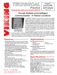
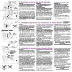
FAILURETO OBSERVETHE FOLLOWINGWARNINGSCOULDRESULTIN INJURY.
Wear hearing protection when
operating this tool.
Turn off air supply and disconnect
air supply hose before installing,
removing or adjusting any
accessory on this tool, or before
performing any maintenance on
this tool.
Air powered tools can vibrate In
use. Vibration, repetitive motions
or uncomfortable positions may
be harmful to your hands and
arms. Stop using any tool if
discomfort, tingling feeling or
pain occurs. Seek medical advice
before resuming use.
Do not carry the tool by the hose.
Do not use damaged, frayed or
deteriorated air hoses and
fittings.
Do not overreach when operating
this tool. Keep body stance
balanced and firm.
I
Operate at 90 p.s.i.g.
(6.2 bar/620 kPa)
maximum air pressure.
NOTICE
PN 48178-1 LABEL
(NON-EU MODELS)
PN 49883 LABEL
(-EU MODELS)
This label must appear on the tool at all times. If it is
lost or damaged, a replacement label is available at
no cost.
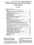
WARNING = Hazards or unsafe practices which could result in severe personal injury, death or substantial
property damage.
CAUTION = Hazards or unsafe practices which could result in minor personal injury or product or property
damage.
NOTICE = Important installation,
2
operation or maintenance information.
ROUTINE
LUBRICATION
REQUIREMENTS
Lack of or an excessive amount of lubrication will affect the performance and life of this tool. Use only recommended lubricants at
below time intervals:
EVERY 8 HOURS OF TOOL OPERATION - Fill lubricator reservoir of recommended F.R.L. with spindle oil (29665). If an in line or
air line lubricator is not used, apply several drops of spindle oil
(29665) in air inlet.
EVERY 180 HOURS OF TOOL OPERATION - Lubricate gearing. Pack bearings, coat shafts and lubricate gears with NLGI #1
“EP” grease (33153). Gearing should contain approximately 3/64
oz. (1.3 g) of grease for single reduction-and 1/16 oz. (1.8 g) for
double reduction.
AIR SUPPLY REQUIREMENTS
For maximum operating efficiency, the following air supply specifications should be maintained to this air tool:
l
l
l
l
AIR PRESSURE - 90 p.s.i.g. (6.2 bar)
AIR FILTRATION - 50 micron
LUBRICATED AIR SUPPLY
HOSE SIZE - 5/16” (8 mm) I.D.
An ARO© model C28231-810 air line FILTER/REGULATOR/LUBRICATOR (F.R.L.) is recommended to maintain the above air
supply specifications.
RECOMMENDED
M20
11
LUBRICANTS
After disassembly is complete, all parts, except sealed or shielded
bearings, should be washed with solvent. To relubricate parts, or
for routine lubrication, use the following recommended lubricants:
Tool maintenance and repair shall be performed by authorized,
trained, competent personnel. Tools, hose and fittings shall be replaced if unsuitable for safe operation and responsibility should
be assigned to be sure that all tools requiring guards or other safety devices shall be kept in legible condition. Maintenance and repair records should be maintained on all tools. Frequency of
repair and the nature of the repairs can reveal unsafe application.
Scheduled maintenance by competent authorized personnel
should detect any mistreatment or abuse of the tool and worn
parts. Corrective action should be taken before returning the tool
for use.
Disassembly should be done on a clean work bench with a clean
cloth spread to prevent the loss of small parts. After disassembly
is completed, all parts should be thoroughly washed in a clean solvent, blown dry with air and inspected for wear levels, abuse and
contamination. Double sealed or shielded bearings should never
be placed in solvent unless a good method of re-lubricating the
bearing is available. Open bearings may be washed but should
not be allowed to spin while being blown dry.
Upon reassembling, lubricate parts where required. Use 33153
grease, or equivalent, in bearings. Use 36460 lubricant for “O”
ring assembly. When assembling “O” rings or parts adjacent “O”
rings, care must be exercised to prevent damage to the rubber
sealing surfaces. A small amount of grease will usually hold steel
balls and other small parts in place while assembling.
When replacement parts are necessary, consult drawing containing the part for identification.
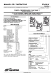
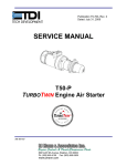
Always use clean, dry air. Dust, corrosive fumes and/or excessive
moisture can damage the motor of an air tool. An air line filter can
greatly increase the life of an air tool. The filter removes rust,
scale, moisture and other debris from the air lines. Low air pressure (less than 90 p.s.i.g.) reduces the speed of the air tool. High
air pressure (more than 90 p.s.i.g.) raises performance beyond
the rated capacity of the tool and could cause injury. Shown below
is a typical piping arrangement,
ARO Part #
Description
Where Used
Air Motor
29665
1 qt. Spindle Oil
36460
4 oz. Stringy Lubricant
“O” Rings & Lip Seals
5 lb. “EP”- NLGI#1 Grease
33153
Gears and Bearings
MAIN LINES 3 TIMES
AIR TOOL INLET SIZE
INSPECTION, MAINTENANCE AND INSTALLATION
TOOL
Disconnect air supply from the tool or shut off air supply and exhaust (drain) line of compressed air before performing maintenance or service to the tool.
LUBRICATOR’
It is important that the tools be serviced and inspected at regular
intervals for maintaining safe, trouble-free operation of the tool.
Be sure the tool is receiving adequate lubrication, as failure to Iubricate can create hazardous operating conditions resulting from
excessive wear.
AIR TOOL INLET SIZE
DRAIN REGULARLY-
Be sure that the air supply lines and connectors are of proper size
to provide a sufficient quantity of air to the tool.
\
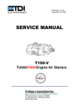
MODELS WITH -EU SUFFIX ARE “EC” COMPLIANT MODELS.
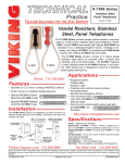
SPINDLE
OPTION
-A
-B
-J
-K
-L
-P
-Q
4
DESCRIPTION
(ITEM NO.)
47340 CHUCK (70)
47341 CHUCK (70)
30384-5 ADAPTER (72)
30384-9 ADAPTER (74)
48459-1 CHUCK (70)
NO OPTION
30712 ADAPTER (75)
M20
11
44.481
RED.
5
I:1 RED.
54
53
47
57
56
M20
11
DL051 B-( )
7
ASSEMBLE
WITH “x”
THIS SIDE
DG051 B-( )
DG052B-(
r(l ITEMS INCLUDED
)
IN SERVICE
KIT NO. 47758-l
NOTSHOWN
49328 BAIL (LEVER THROTTLE)
48472 BAIL ASSEMBLY (PISTOL GRIP, OPTIONAL)
48178-l WARNING LABEL (NON-EU MODELS)
49883 WARNING LABEL (-EU MODELS)
7
DISASSEMBLY/ASSEMBLY
Assemble bearing (42) into end plate (41) pressing on outer
race of bearing.
Assemble end plate (41) to rotor, pressing on inner race of
bearing. Be sure rotor turns without binding.
Insert locating pin (45) into .096” diameter blind hole at bottom
of motor cavity in housing.
Align notches of end plates and cylinder and install motor into
housing, aligning notches with locating pin (45).
Grease and assemble “O” ring (43) to end plate (41).
Assemble spacer (44) to motor.
Assemble gearing to tool.
Never apply excessive pressure by a holding device which
may cause distortion of a part.
Apply pressure evenly to parts which have a press fit.
Apply even pressure to the bearing race that will be press
fitted to the mating part.
Use correct tools and fixtures when servicing this tool.
Don’t damage “O” rings when servicing this tool.
Use only genuine ARO replacement parts for this tool. When
ordering, specify part number, description, tool model number
and serial number.
GEARING
PISTOL GRIP HOUSING
DISASSEMBLY
PISTOL GRIP HOUSING
ASSEMBLY
Grease “O” ring (23) and assemble into housing (21).
Assemble retaining ring (28) to valve stem (29).
Grease “O” ring (27) and assemble to valve (26).
Assemble valve (26) to valve stem, with smallest diameter of
valve going on valve stem first.
Grease “O” ring (25) and assemble to valve stem, securing
valve (26).
Single Direction models: Assemble valve stem thru plug (35)
and assemble plug into housing (21) aligning .102” diameter
holes in housing and plug.
Reversible models: Assemble washer (30) and spring (31)
over valve stem. NOTE: Assemble washer with “x” facing “O”
ring (23). Assemble reverse valve (33) to valve bushing (32).
NOTE: Position .102” diameter hole thru bushing to align with
slot thru side of reverse valve. Assemble valve stem and components thru reverse valve (33) and bushing (32) and assemble into housing, aligning .102” diameter holes in housing
and bushing.
Assemble trigger (34) securing with pin (22). NOTE: Assemble pin from left side of housing.
Assemble filler(s) (20) and muffler (19) to housing, securing
with inlet adapter (18).
Clean and replace screen (9) in inlet adapter.
ASSEMBLY
Assemble spacer (49) and one bearing (50) into ring gear (48,
69 or 63) pressing on outer race of bearing.
Coat shafts of spindle(s) with ARO 33153 grease.
Assemble gears, containing bearings (57) to shafts of mating
spindle.
Assemble carrier assembly to spindle assembly of double reduction gearing.
Lubricate sets of gears liberally with ARO 33153 grease (see
“Routine Lubrication Requirements”, page 3).
Assemble spindle(s) and gearing into ring gear. Rotate
spindle and gears to align gear teeth with splines of ring gear.
Assemble spacer (51) and bearing (50) into ring gear, pressing on inner race of bearing.
Assemble washer (52) to ring gear, securing with lock nut (53).
Assemble ring gear and components to tool and tighten, using
a wrench on flats of ring gear.
Assemble spacer (54) and drive option to tool.
MOTOR DISASSEMBLY
Remove gearing from tool.
Remove spacer (44) and “O” ring (43).
Tap front edge of housing to remove motor assembly. Locating pin (45) should also come out.
Grasp cylinder in one hand and tap drive end of rotor (38) with
a soft face hammer; motor will come apart. NOTE: Bearings
are light press fit on rotor.
Remove end plate (37) and bearing (36) from rotor.
LEVER THROTTLE HOUSING DISASSEMBLY
Clamp inlet adapter (8) in a smooth face vise.
Unthread housing (1 or 14) using a strap type wrench.
Remove spacer (7) diffuser washer(6) exhaust cap (5) fillers
(4) spring (3) and valve rod (2). NOTICE: Do not remove or
adjust rubber portion of valve rod (2) as it is preset at the factory. However, if air leakage occurs due to wear, unscrew rubber
portion of valve rod NOT more than one complete turn (counterclockwise).
Reversible models: Remove pin (77) ball (15) valve body
(16) and spring (17).
Remove throttle pin (11) and spring (10).
Remove screen (9) from inlet adapter (8).
MOTOR ASSEMBLY
Lubricate bearing (36) with ARO 33153 grease and assemble
into end plate (37) pressing on outer race of bearing.
Assemble end plate (37) to rotor, pressing on inner race of
bearing.
Coat five rotor blades (39) with ARO 29665 spindle oil and assemble to rotor slots - straight side out.
Coat i.d. of cylinder (40) with ARO 29665 spindle oil and assemble over rotor. NOTE: Air inlet slots in end of cylinder must
be aligned with two air inlet holes in end plate (37).
DISASSEMBLY
Remove spiral pin (22), driving it out the left side of housing.
Single Direction models: Remove trigger (34) plug (35) valve
assembly (24) and “O” ring (23).
Reversible models: Remove trigger (34) reverse valve (33)
valve bushing (32) spring (31) washer (30) valve assembly
(24) and “O” ring (23).
Remove “O” ring (25) valve (26) “O” ring (27) and retaining
ring (28).
Remove inlet adapter (18) releasing muffler (19) and filler(s)
(20).
Remove screen (9) from inlet adapter (18).
Clamp tool in a smooth face vise- pistol grip models, clamp on
handle (21) - straight models, clamp on inlet adapter (6).
Remove drive option from tool (chuck, square drive, etc.).
Unthread and remove ring gear (48, 59 or 63) and components using a wrench on flats of ring gear.
Remove spindle(s) and gears from ring gear. NOTE: Keep
gears grouped with mating spindle when disassembling
double reduction gearing.
Remove lock nut (53) releasing washer (52) bearings (50)
and spacers (49 and 51).
Do not remove gears (55 or 64) from carrier assembly unless
damage is evident. Gears are press fit onto carrier assemblies.
GEARING
INSTRUCTIONS
LEVER THROTTLE
_
HOUSING
ASSEMBLY
Assemble spring (10) and throttle pin (11) into housing, aligning slot in throttle pin with air inlet holes in housing.
DISASSEMBLY/ASSEMBLY
Reversible models: Assemble spring (17) and valve body (16)
into housing, aligning ball slot in valve body with slot in housing.
_ Assemble valve rod (2) into housing. NOTE: Throttle pin (11)
should not pull out when valve rod is seated properly.
_ Assemble two fillers (4) to exhaust cap (5).
l
PART NUMBER
4
6
7
9
10
11
12
13
14
15
16
17
18
19
20
21
22
23
24
25
26
28
29
30
31
33
34
36
37
38
41
42
Reversible models: Assemble ball (15) and pin (77) into slots
of housing and valve body (16).
Assemble exhaust cap (5) to housing, aligning lever (12) with
- throttle pin (11).
_ Assemble spring (3) diffuser washer (6) and spacer (7) to tool,
securing with inlet adapter (8).
_ Clean and replace screen (9) in inlet adapter.
l
FOR ORDERING
PART NUMBER
t
1
2
Housing ............................
Valve Rod Assembly .................
Spring ..............................
Filler (2 req’d) .......................
Exhaust Cap ........................
Diffuser Washer .....................
Spacer .............................
Inlet Adapter ........................
Screen .............................
Spring ..............................
Throttle Pin .........................
Lever ..............................
Roll Pin .............................
. .........
Housing ..................
Ball ................................
Valve Body ..........................
Spring ..............................
Inlet Adapter ........................
Muffler Assembly ....................
Filler (model DG051 B requires 2) ......
Pistol Grip Housing ..................
Spiral Pin ...........................
“O” Ring ............................
Valve Stem Assembly ................
“O” Ring ............................
Valve.. .............................
“O” Ring.. ..........................
Retaining Ring ......................
Valve Stem .........................
Washer .............................
Spring ..............................
Valve Bushing .......................
Reverse Valve .......................
Trigger .............................
Plug ...............................
Bali Bearing .........................
Rear End Plate ......................
Rotor (see chart, page 4)
hexdrive.. .........................
splinedrive.. .......................
Blade (5 req’d) ......................
Cylinder
for single direction models ............
for reversible models ................
Front End Plate ......................
Ball Bearing .........................
MOTOR ASSEMBLY (includes items 36
thru 42) (see chart, page 4)
“O” Ring.. ..........................
Spacer .............................
INSTRUCTIONS
46723
46354
41654
46452
46448
46449
47205
46377
33911
46374
46296-2
46326
Y 178-26
46486
Y16-204
46476
41654
46385
46857
46851
47367
46849
Y325-15
46848-2
Y325-3
45473
Y325-7
Y180-13
46847-2
46379-l
41100
46381
46299
46298
46406
47724
46312-l
46454
46470
46413
48201-l
46311
47722
Y65-13
Y325-214
46412
FOR ORDERING
i
Locating Pin
for lever throttle models ..............
for pistol grip models .................
46 Drive Plate ..........................
47 Spindle Assembly
for single direction models ............
for reversible models ................
41 Ring Gear (single reduction, 51 teeth) . .
Spacer .............................
4I
50 Ball Bearing (2 req’d) .................
51 Spacer .............................
52 Washer .............................
53 Lock Nut ............................
54 Spacer .............................
55 SunGear(1 or 2 req’d)3.431 ratio(21teeth) ...
56 PlanetGear(3 or 6 req’d)3.431 ratio(15teeth) .
57 Needle Bearing (3 or 6 req’d) ..........
58 Spindle Assembly
for single direction models ............
for reversible models ................
59 Ring Gear (single reduction, 39 teeth) . .
PlanetGear(3 or 6 req’d)6.6711ratio(21teeth) .
60 Spindle Assembly
for single direction models ............
for reversible models ................
Carrier Assembly ....................
63 Ring Gear (double reduction) ..........
64 Sun Gear 4.4:1 ratio (15 teeth) .........
65 Planet Gear (3 req’d) 4.4:1 ratio (18 teeth)
66 Carrier Assembly ....................
67 Carrier Assembly ....................
68 Spindle Assembly
for single direction models ............
for reversible models ................
69 Carrier Assembly ....................
70 Chuck
“O”
- 1/4” capacity ....................
1/16” - 3/8” capacity .................
O” - 1/4” capacity ....................
71 Screw.. ............................
72 3/8” Square Drive Adapter ............
73 Roll Pin .............................
74 1/2” Square Drive Adapter ............
75 1/4” Hex Ball Lock Adapter ............
76 Roll Pin .............................
77 Pin .................................
45
SERVICE KIT includes items 3, 4, 9, 10,
13, 15, 17, 19, 20, 22, 23, 25, 27, 39, 43,
52 and 77 ..........................
47723-2
47723-l
46716
47805-5
478075
46713
48496
Y65-13
46706
47682
46704
46705
46465
46899
42315
47805-3
47807-3
46714
46901
47805-l
47807-l
46521
46712
46466
46900
46522
46721
47805-2
47807-2
47544
47340
47341
48459-1
47060
30384-5
Y178-39
30384-9
30712
Y178-41
49983
47756-l
9
MODELDG052B-10-P
10
:
1
{
1
i
i
I
I\-
Part of worldwide Ingersoll-Rand
PN 49999-042