1
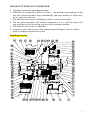
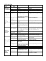
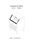
Automatic Ice Maker Service Manual MODEL IM-2842 Table of contents How the Icemaker works ---------------------------------------------2-10 Cooling System -----------------------------------------------------------------2 Water System ---------------------------------------------------------------- 3-4 Wiring Connections and Controller------------------------------ ---------4-7 Exploding Drawing ----------------------------------------------------------7-8 TroubleShooting ------------------------------------------ ------------- 9-17 Before Maintenance------------------------------------------------------------9 Basic Checking -----------------------------------------------------------------9 TroubleshootingGuide----------------------------------------------------- 9-14 Adjustment and Replacement---------------------------------------------------- 15-17 Replace the controller---------------------------------------------------- -----15 Adjust the size of ice cube----------------------------------------------------15 Replace the water pump-------------------------------------------------------16 Replace the compressor-------------------------------------------------------17 Replace the fan motor and fan blade------------------------------------ ----17 IMPORTANT: The service manual is based on the user manual. Before servicing, please read user manual and service manual carefully. The service operation should be implemented by qualified technician. How the Icemaker Works Please refer to the section “Operation of user manual” from page 12 to 14 . It describes clear how the icemaker makes ice and uses the water. There are 3 systems including Cooling System, Water System and Wiring Connection and Controller. Cooling System II ITEM NO 1 2 3 4 5 6 7 8 9 10 11 12 13 14 15 16 17 CODE 1858420900 1861512102 1861530100 1880013104 1880008201 1805000600 1861502502 1854701800 1861501701 1880024700 1860700100 1880020202 1858200601 1858201300 1851700200 1851700802 1854205900 DESCRIPTION Compressor Discharge tube Cu three ways Condenser Drier and filter Capillary tube Connection tube Hot gas valve Hot gas tube Evaporator (Ice Mold) Fan blade(φ200X28°) suction pipe Motor 5W Motor 10W Temperature sensor of the evaporator Temperature sensor of the condenser Control box During the ice-making stage, the hot gas solenoid valve is closed. The hot refrigerant gas is pumped out off compressor to condenser. The hot gas is cooled by fan forced air to warm liquid refrigerant after passing through the condenser. The drier & filter reduces the possible dirty and humidity in the refrigerant. The evaporator is cooled by the refrigerant. So ice can formed on the evaporator during water is sprayed to the evaporator. Low pressure refrigerant gas may go back compressor from the evaporator. During the ice harvest stage, the solenoid valve is open. The hot refrigerant gas is pumped out off compressor to evaporator through hot gas valve. As the hot gas is not cooled by the condenser, the refrigerant makes the evaporator (ice mold) warm. So some ice touching the evaporator is thawed. All of ice can slide down to the ice storage bin. Water System When the water supply pipe is connected with the main water supply, water will fill the water trough through the floater valve till enough water inside water trough makes floater valve close. During ice-making stage, water is pumped from the water trough to the water distribution tube. The distributed water flow the surface of evaporator. Most parts of water go back water trough. Some water is frozen on the evaporator step by step. The floater valve will open and fresh water is recruited at any moment. ITEM NO 1 2 3 4 5 6 7 8 9 10 11 12 13 14 15 CODE 1811306100 1864526301 1864529100 1864515100 1811206006 1880001701 1864802002 1858904400 1811330102 1861701802 1864550602 1864550702 1880024700 1854005700 1813406016 1864608400 DESCRIPTION Water supply tube Water inlet connector Nut of water inlet tube Supporting tube Water pump inlet tube Floater valve Water trough Water pump Water pump outlet tube Ice slideway Water distribution tube Evaporator (Ice Mold) Magnetism switch Gasket Screw cap Wiring Connection : Circuit Description 1. Electrify Status For The First Time As the icemaker is properly installed. switch on the water tap, let the water trough full (reach on the level), then turn the Power switch to the ON position on the panel. The icemaker will start working automatically In this status, the time is fixed about 3 minutes. This function is also helpful to protect the compressor avoiding restart within 3 minutes. At this status, the White, Green, Yellow and Red LEDs are light together. 2. Ice-making Status The compressor, motor fan and pump are powered on. The hot gas solenoid valve is powered off. When this green LED is lit, the unit is working in the ice making mode controlled by a temperature probe on the evaporator. When the green LED is flashing, the unit is working in the ice making mode controlled by a fixed timer. The fan motor is also controlled by a condenser sensor. When the ambient temperature is too lower, the motor fan stop working for good condensation to refrigerant. 3. Ice Harvest Status The pump is powered off. The hot gas solenoid valve, compressor and motor fan is powered on. The fan motor is also controlled by a condenser sensor. When the ambient temperature is too lower, the motor fan stop working for good condensation to refrigerant. The Yellow LED indicates the ice harvest status. 4. Ice Full Status And Cold Preservation Stage If the ice bin is fulfilled with ice, the machine stops making ice and turn to cold preservation stage automatically. In this status, the compressor works regularly to keep the lower temperature for lower ice melting. The rest of the electric components are powered off. The WHITE LED indicates the ice full status and the GREEN AND YELLOW LEDs together indicates the preservation status . cold 5. Cleaning Status Turn the machine CLEAN SWITCH at the CLEAN in 3 minutes after the POWER SWITCH is turned on, the machine turn to Cleaning Status. At this status, the pump is powered on. Compressor, motor fan and the hot gas solenoid valve are powered off. The GREEN and YOLLOW LEDs are flashing together. To stop the cleaning mode, turn the machine “OFF” at the Power switch or it will turned off automatically after 30 minutes. NOTE: In order to start the Clean Status the power switch must be on. The CLEAN switch must be turned in 3 before the COMPRESSOR starts. To clean, it is no use turning the CLEAN switch when machine is in ice-making status or ice-harvest status. Controller box: Instructions for LEDs and buttons: 1. White LED: Ice full indicator light. When this LED is lit, the ice storage bin is full of ice or there is something between the ice-full sensor and the evaporator. The unit will stop making ice. When ice cubes are taken out of the ice storage bin making the ice-full probe free, the white LED will keep flashing for 3 minutes. Then the unit will restart and return to the ice making mode. 2. Green LED: Ice making indicator light. When this LED is lit, the unit is working in the ice making mode controlled by a temperature probe on the evaporator. When the green LED is flashing, the unit is working in the ice making mode controlled by a fixed timer. 3. Yellow LED: Ice harvest indicator light. When this LED is lit, the unit is working in the ice harvest mode controlled by ice-full probe . When green LED and yellow LED is lit, it means the unit is working in the cold preservation stage . 4.Red LED: power indicator light. The power is on when the red LED is lit. 5. Mode button: Mainly for service. When this button is pressed, it can change from ice making mode to ice harvest mode, or from ice harvest mode to ice making mode. You can judge the mode from the status of the green and yellow LEDs. 6. Ice size adjust: Turn the screw clockwise, and the size of individual ice cubes will be larger in the next cycle; the cycle time will be longer. Turn the screw counter clockwise, and the ice size will be smaller in the next cycle. NOTE: It is not a good idea to adjust the ice size often or for no good reason, because the controller may damaged. IMPORTANT *1. Avoid water to the controller box. *2. To start the Clean Status the power switch must be on. The CLEAN switch must be turned in 3 minutes before the COMPRESSOR starts. *3. When turn the machine “ON” at the Power switch, the compressor, motor fan and pump will be delayed 3 minutes to power on to protect compressor. At this moment, the Red, Green, Yellow and White LEDs are light together. 3 MAJOR FUNCTIONS OF CONTROLLER 1. Completely automatic operating procedure. 2. When the ice storage bin is full of ice cubes, the machine stops making ice and turn into cold preservation stage automatically and starts making ice again after the ice cubes are removed. 3. The different colors of the LED display indicate various work modes. 4. The fan motor responds to the ambient temperature. If it is cold, the motor will stop working to keep the cooling system in good working condition. 5. The thickness of ice cubes is adjustable. 6. A sensitive probe and accurate timer enhance the performance of the ice maker. 7. Built-in compressor protection system. Exploding Drawing 4 Spare parts list of IM-2842 ITEM NO 1 2 3 4 5 6 7 8 9 10 11 12 13 14 15 16 17 18 19 20 21 22 23 24 25 26 27 28 29 30 31 32 33 34 35 36 37 38 CODE 1864701602 1864800100 1860106304 1860110803 1860410602 1864514100 1864536200 1860004907 1858420900 1854701210 1854701800 1860007701 1860111106 1860604901 1811306100 1858420900 1858441300 1864802002 1858201708 1858201800 1860601804 1880001701 1864529100 1811206006 1811330102 1858904400 1864526301 1851700802 1851700200 1864532702 1864550602 1880024700 1861701802 1880020202 1853701905 1854005700 1861501701 1853110500 DESCRIPTION ice storage bin Ice scoop top panel down right panel right slide way Drain nut Drain connector right cover wind panel condenser Hot gas valve body (EVU3) Hot gas valve coil(042N4212) back panel right back support little support Water supply pipe Compressor compressor starting device component water trough evaporator support water trough support water pump support Floater valve water inlet pipe screw water inlet pipe Water out tube of pump Water pump Water inlet Temperature sensor of condenser Temperature sensor of evaporator Water drain pipe water sprinkler Evaporator (Ice Mold) Ice full probe suction pipe Wiring harness Magnetism switch discharge pipe Power supply line 5 39 40 41 42 43 44 45 46 47 48 49 50 51 52 53 54 55 56 57 58 1860601507 1860004804 1858200601 549738100 1858201300 1860508201 1860111204 1860410502 1860110704 1860601609 1854000500 1864901700 1860600805 59 1860617100 60 61 62 1854800300 1854205900 1880013104 1864806902 1860111700 1803200100 1880014901 1860604614 1880008201 1861530100 back support fan motor cover Motor 5W Fan blade (φ200X28°) Motor10W fan motor bracket left back support left silde way down left panel left support Power switch operator buttom cover under louver door stability support locked screw foot compressor base Drier T shape three ways control panel of FIM200 control box) 15A fuse of control box Control box Condenser 6 Troubleshooting ELECTRICAL SHOCK HAZARD Disconnect Electrical Power Before Beginning Removal of Parts Before Maintenance 1. Check out the user if the user uses a 115 VAC, 60Hz. only 15ampere electrical supply, and have properly grounded, ensure the maintainer against electrical shock. 2. Check out the leads loose? Turn off? Short circuit? If have such problems, foreclose in turn. Basic Checking The icemaker has some trouble, through the appearance phenomena judges. So the service technician must check it thoroughly, then maintain. Hearing Hearing the user 's depiction about the icemaker at using process and the phenomena. Try to understand what is the defect and how did the user operate the icemaker before calling for service. If the running sound is normal? Looking Check the pipe of cooling system, especially the welding point. If there is some oil, the gas is leak out so that no ice making or less ice produced. If the cycle of the ice making and harvest is normal? Check the water system, especially the connection. If there is some water leakage. Check if the water filter needs to be replaced. Check if the icemaker installed according to the user manual. Check if the icemaker needs to be cleaned. Touching Touch the hot gas pipe (with the evaporation weld), feeling the temperature. At the ice making stage, feeling cool. At the ice harvest stage, feeling hot. Touch the capillary tube (the drier nearby), feeling tepefaction. Troubleshooting Guide This troubleshooting guide in the user manual should be read before this guide. Be sure only when the trouble shooting in user manual can’t help you solve the problem, turn to this guide. Troubleshooting Guide 1.The machine does not make ice 7 Problem kinds The machine don't operate Check part or point Plug Socket Power switch Fuse Wiring connection Voltage Ice full probe Ice full probe wiring Electric component Control box Water supply tap Water supply pipe Water System Water line Water pump The compressor The icemaker is unplugged. Socket is damaged The icemaker power switch turns to OFF. The fuse is blown. Some wiring connection is incorrect or loosed The voltage of the power supply is low. The ice full probe is out of function. The ice full probe is covered by something Some wiring is damaged Some electric component fail The control box fail The water supply tap is turn off. The water supply pipe is not proper connected or maybe kinked Some water line leaks. Probable Correction Plug the icemaker in. Check and replace Turn the icemaker power switch to ICE. Replace fuse. Check and re-connect Add manostat. Replace a new one. Clear the probe and make the ice-full probe is free. Replace a new one Find the controller, press the mode button to change the mode. It is helpful to judge which part is out of function Replace a new one Turn on the water supply tap. Reconnect the water supply pipe. Water supply pressure is lower. Water inlet blocks Plug into again. Clean it, see user and care manual "ice making system cleaning" Adjust the water supply pressure within the range of stated range. Check and clear it Water dump valve leakes, Replace the water dump valve Water pump damages The lines of the water pump loose. The housing of water pump leaks. Replace water pump. The water line blocks Water inlet Water dump valve Problem kinds Possible Cause Check part or point Wiring connects The start relay/therma l protect The startup Possible Cause loose. Plug into again Replace water pump. Probable Correction Plug tightly, or replace. Be damaged. Replace the start relay/thermal protect of the compressor Be turnoff. Replace the compressor. 8 doesn't start or start frequency coil / running coil Condenser Fan The Electronic control box Refrigerant The compressor run but no ice Be turnoff. The motor of the compressor is short circuit. The condenser may be dirty. The fan may be dirty or damaged The control box is damaged Refrigerant leaks completely Capillary tube Capillary tube is blocked Vent The vent is obstructed around the ice machine Hot gas valve damaged Hot gas valve The Electronic control box Replace the compressor. Replace the compressor. Clean the condenser. Clean or Replace the fan . Replace the Electronic control box. Add low side access valve, locate leak, recover refrigerant, replace drier, evacuate and weigh in the data plate charge. Add low side access valve, recover refrigerant, replace hot gas valve, replace drier, evacuate and weigh in the nameplate charge. Clean the vent Replace The model of making ice doesn't turn to harvest. Replace the Electronic control box. Tthe unit is working in the Work in normal mode cold preservation stage mode controlled. 2.Low production Problem kinds Cooling System Check part or point Refrigerant Condenser The ambient temperature Fan Hot gas valve Electronic control box Sensor Possible Cause Refrigerant leaks partially The condenser may be dirty. The ambient temperature is high or too low The fan is dirty or damaged Hot gas valve performance poor, leads to few ice is produced. The setting temperature of Electronic control box is low. The sensor of temperature damages Probable Correction Recharge. Clean the condenser. Check the ambient and air flow Clean or repalce Replace the hot gas valve See the service manual "adjust the size of ice cubes" Replace the sensor of temperature. 9 Water distribution tube Water System Water line Silica gel tubes Water dump valve Floater valve The water tube blocks distribution The water quality is too poor. The water line blocks The silica gel tubes distort, lead to block. The water dump valve bad, the water leakes The floater valve leaks. Lead to few ice produced. Clean the water distribution tube Using a filter apparatus installed in front of the water inlet valve. Make the silica gel tubes resile Replace the water dump valve Repair or replace 3. Ice Cube is not OK Problem kinds Cubes are too small Cubes are too big Check part or point Condenser The ambient temperature Electronic control box Refrigerant Electronic control box Sensor The ambient and water temperature The cubes are partially formed--hav e ragged sides or white and deformity Possible Cause The condenser is dirty or the air grills are covered The ambient temperature is too high. The setting temperature is high. Refrigerant leaks The setting temperature of Electronic control box is low. Temperature sensor of the evaporator damages The ambient temperature and water temperature is too low. The water quality is poor Clean the condenser. Leave space around the machine Adjust the ambient temperature. Ice machine is dirty The water distribution tube blocks partially Clean and sanitize the ice machine Clean the water distribution tube The water pump is dirty Clean the water pump inside The water floater is bad Replace the water floater Water trough level is too Adjust the water floater Water quality Evaporator Water distribution tube The water pump The water lack Water trough Probable Correction See the service manual "adjust the size of ice cubes" Recharge. See the service manual "adjust the size of ice cubes" Replace the sensor of temperature. Adjust the temperature. Using a water-soften / filter apparatus installed in front of the water inlet valve. low 10 4.Other problems Problem kinds The body is electrified Scales occur frequently inside the machine Noise during operation is big Check part or point Earth line Lines Electric component the water quality Spring of the internal compressor Water pump Pipeline system Fan motor The operation Water is leaking out the unit The water distribution tube doesn't spray Water supply connection Water line Water drain pipe Lines of the water pump Water pump Water distribution tube Ice full probe Hot gas valve Harvesting ice is difficult Ice mold of the evaporator Refrigerant Ice machine Possible Cause The earth line isn't in the socket. The lines are creepage. The electric component is creepage, The rigidity of the water quality is too high. The spring of the internal compressor drops. Probable Correction Please use the socket meeting the standard. Adjust, reconnect /replace lines Replace this electric component. Using a water-soften apparatus installed in front of the water inlet. Replace the compressor. The noise of the water pump Pipeline system resonate The fan motor loose, the clearance of the rotor is bigger, the fan blade turns back A few water drops to the floor when you open the door to take out ice from ice storage bin. Water supply connection leaking. Some water line leaks. No water drain pipe or connection leaking The lines of the water pump loose. Replace the water pump. Water pump damages The water distribution tube blocks Replace water pump. Clean the water distribution tube The ice full probe is broken or can not turn back normal position. The hot gas valve is poor, The hot gas valve damage The ice mold is dirty, or polishing degree is poor. Refrigerant leaks Repair or replace the probe Ice machine is not proper Level the ice machine Clear pipeline system Relocate the fan motor / replace Normal condensation on the door or some water together with ice. Take care when you take out ice. Tighten fitting. Plug into again. Replace the water drain pipe Plug into again Replace the hot gas valve Replace the hot gas valve Clean the ice mold, or replace the evaporator. Recharge leveled 11 The ambient and water temperature Ice cubes size The evaporator is hot more than 4 minutes Hot gas valve Refrigerant Electric control box The ambient and water temperature is too low Adjust the temperature. The size is too big. The lines of the hot gas valve loose. Hot gas valve performance poor or break Refrigerant leaks The electric control box is wrong See “the adjust of ice cube size”. Plug into again Replace the coil of hot gas valve if only because of the coil. Recharge Check the control box Adjustment and Replacement Replace Control box, fuse and the sensor of temperature ELECTRICAL SHOCK HAZARD Disconnect Electrical Power Before Beginning Removal of Parts Remove the rear cover, front panel, Locate the Electronic control box, Pull out the sensors of temperature (one at the evaporator, another at the condenser). loosen the screws of rooting the Electronic controller, replace a new one. Reverse the above step to replace. If you need replace the fuse, open the front panel of the control box, you will find the figure. According the figure, take out the fuse, replace a new one. Reverse the above step to reassemble. If you need replace the sensors of temperature, pull out the sensor of temperature, open the panel of the controller box, pull out the other side, replace a new one. Reverse the above step to reassemble. Adjust the size of ice cube The cube size should only be adjusted to bring the cubes to the correct shape, the overall size can't be adjusted, Try to adjust the cubes size when the ice maker is work in the Ice Harvest Status. 12 1. Power off the icemaker. 2.Remove the front panel, locate the Electronic control box, 3.Locate the cube size adjustment screw, and to make fuller cubes, turn the screw clockwise about Control box 1/36 turn (10°-15°). This will make the freezing cycle longer. 4. To shorten the freezing cycle and make cubes that are not as full, turn the adjustment screw 1/36 turn (10°-15°) counter clockwise. 5.After the next freezing cycle, the cubes should have responded to the adjustment, if another adjustment is required, do it early in the freeze cycle. . Correct Correct size size Too big Too small Expert advises the cube size have been adjusted ok before leave factory, had better not adjust it. Replace the water system components Please see the water system drawing. The water leakage should be checked after this kind of operation 13 Before replace the water system components, it will be necessary to drain the system of water. Replace the water pump Disconnect electrical power. Remove the front cover. Unplug the lines connector with the water pump, the water outlet tube of pump. Loosen the screws, replace a new one. Reverse the above step to reassemble. Replace the Water Dump Valve The water dump valve normally does not require removal for cleaning. To determine if removal is necessary: 1. Locate the water dump valve. 2. Set the toggle switch to ICE. 3. While the ice machine is in the freeze mode, check the dump valve’s clear plastic outlet drain hose for leakage. A. B. If the dump valve is leaking, remove, disassemble and clean it. If the dump valve is not leaking, do not remove it. Instead, follow the “Ice Machine Cleaning Procedure”. Replace the cooling system components Replace the condensing components, See Figure “cooling system” 1.Replace the compressor and the compressor kit (includes relay, thermal protect). If only need replace the compressor kit, remove the top panel and left panel, locate the compressor, take the clip, replace the wrong, Reverse the above step to reassemble. If need replace the compressor, remove the top cover, locate the compressor. Unplug the lines and taken out the earth line, open the Process/Suction, evacuate refrigerant, take out the compressor, replace a new one, joint together, then recover refrigerant, weigh in the nameplate charge. Reverse the above step to reassemble. 2. Replace the fan motor and fan blade. Remove the top and right panel. locate the fan motor, unplug the lines connecting with the fan motor, loosen the screws of holding bracket and fan motor bracket, taken out the damaged, replace a new one Reverse the above step to reassemble. 3. Replace the hot gas valve, drier and evaporator. 14 Remove the top panel. Locate the drier and hot gas valve, weld open , ,replace the drier and hot gas valve, weld ,recover refrigerant , evacuate and weigh in the nameplate charge. Reverse the above step to reassemble. If need replace the evaporator. Remove the front and top panel, locate the evaporator, open the process/suction , weld open the two welds, replace a new one. Recover refrigerant, evacuate and weigh in the nameplate charge. Reverse the above step to reassemble. 15