1
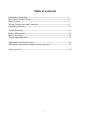
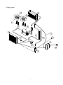
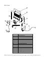
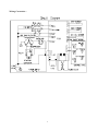
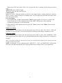
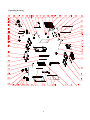
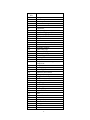
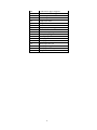
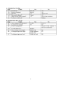
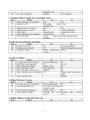
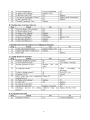
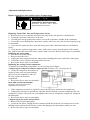
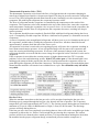
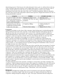
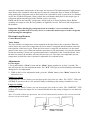
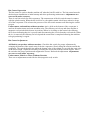
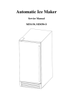
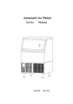
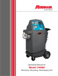
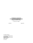
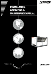
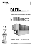
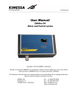
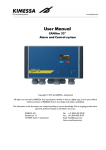
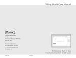
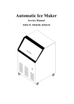
Automatic Ice maker Service manual MIM452 MIM600 MIM1000 1 Table of contents Installation Guidelines ---------------------------------------------------------3 How the Ice Maker Works ----------------------------------------------------4 Water System --------------------------------------------------------------------7 Wiring Connections and Controller ------------------------------------------9 Exploding Drawing -------------------------------------------------------------12 TroubleShooting ----------------------------------------------------------------14 Before Maintenance ------------------------------------------------------------14 Basic Checking ------------------------------------------------------------------14 TroubleshootingGuide ----------------------------------------------------------15 Adjustment and Replacement -------------------------------------------------20 Advanced component troubleshooting techniques --------------------------21 Spare parts list ------------------------------------------------------------------- 28 2 Installation Guidelines Note: Installation should be performed by a trained Service Technician. For proper operation of the ice machine, the following installation guidelines must be followed. Failure to do so may result in loss of production capacity, premature part failures, and may void all warranties. Ambient Operating Temperatures Minimum Operating Temperature: 50°F (10°C) Maximum Operating Temperature 100°F (38°C). Note: These products are not designed for outdoor installation. Incoming Water Supply Minimum incoming water temperature: 40°F (5°C) Maximum incoming water temperature: 90°F (32°C) Minimum incoming water pressure: 15 psig Maximum incoming water pressure: 80 psig Note: If water pressure exceeds 80 psig, a water pressure regulator must be installed. Drains: Route bin drain, purge drain and water condenser drain individually to a floor drain. The use of condensate pumps for draining water on equipment producing over 200 lbs./day is not recommended by Manufactor. We assumes no responsibility for improperly installed equipment. Water Filtration A water filter system should be installed with the ice machine. Clearance Requirements Self contained air cooled ice machines must have a minimum of 6 inches (15cm) of clearance at the rear, top, and sides of the ice machine for proper air circulation. Since undercounter machines breathe from the front, top and side clearances are minimal. Stacking If the ice machines are to be stacked, refer to the instructions in the stacking kit. We does not endorse stacking aircooled ice machines. Dispenser Application A thermostatic bin control kit must be installed if the ice machine is placed on a dispenser. A bin top may or may not be required. Ice Maker Maintenance Maintenance Procedure 1. Clean the icemaking section per the instructions below. Cleaning should be performed a minimum of every 6 months. Local water conditions may require that cleaning be performed more often. 2. Check ice bridge thickness. Proper thickness should be 1/16-1/8’’. 3. Check water level in trough. See troubleshooting for proper water level and adjustment. 4. Clean the condenser to insure unobstructed air flow. 5. Check for leaks of any kind: Water, Refrigerant, Oil, Etc. 6. Check the bin switch for proper adjustment. 7. Check all electrical connections. 3 8. Oil the fan motor if the motor has an oil fitting. Cleaning and Sanitizing Harvest problems may occur if the following procedures are not performed every 6 months. 1. Remove the ice machine front panel. 2. Make sure that all the ice is off of the evaporator. If ice is being made, wait for cycle completion, then turn the machine “OFF” at the selector switch. 3. Remove or melt all ice in the storage bin. 4. Add recommended amount of approved ice machine cleaner to the water trough according to label instructions on the container. 5. Initiate the clean cycle at the controller board switch by turning on the machine and activating the switch marked as “CLEAN”. Note: This must be done within 3 minutes of turning the machine “ON”. Allow the cleaner to circulate for approximately 15 minutes to remove mineral deposits. 6. After 15 minutes (or 30 minutes automatically), stop the process and drain the sump. Refill with clean water run another 5 minutes and drain again. Fill the trough with fresh incoming water. 7. Terminate the wash cycle at the switch by placing the switch in the “OFF” position. Remove the splash curtain (if available) and inspect the evaporator and water spillway (the plastic top of the evaporator) to assure all mineral residue has been removed. 8. If necessary, wipe the evaporator, spillway and other water transport surfaces with a clean soft cloth to remove any remaining residue. If necessary, remove the water distribution tube, disassemble and clean with a bottlebrush. Reassemble all components and repeat steps 4 through 7 as required to remove residue. 9. Turn OFF ice machine water supply and clean the water trough thoroughly to remove all scale or slime buildup. If necessary, remove the water trough to reach all splash areas and float. 10. Prepare 1½ to 2 gallons (5.7 to 7.5 liters) of approved (EPA/FDA) sodium hypochloride food equipment sanitizer to form a solution with 100 to 200 ppm free chlorine yield. 11. Add enough sanitizing solution to fill the water trough to overflowing and activate the switch to the “CLEAN” position and allow circulation to occur for 10 minutes and inspect all disassembled fittings for leaks. During this time, wipe down all other ice machine splash areas, plus the interior surfaces of the bin, deflector and door with the remaining sanitizing solution. Inspect to insure that all functional parts, fasteners, thermostat bulbs (if used), etc. are in place. 12. After 3 minutes, stop the process and drain the sump. Refill with clean water run another 5 minutes and drain again. Fill the trough with fresh incoming water. 13. Place the switch to the “ON” position and replace or close the panel. Discard the first two ice harvests. How the Ice Maker Works Refer to the Operation section of the User’s Manual (pages 12 to 14) for a clear description of how the ice maker makes ice and uses water. There are 3 systems: the Cooling System, the Water System and the Electrical System. 4 Cooling System 5 ITEM NO 1 2 3 4 5 6 7 8 9 10 11 12 13 14 15 16 17 DESCRIPTION Compressor Discharge tube Cu three ways Condenser Drier and filter Capillary tube Connection tube Hot gas valve Hot gas tube Evaporator (Ice Mold) Fan blade(φ200X28°) Suction pipe Motor 5W Motor 10W Temperature sensor of the evaporator Temperature sensor of the condenser Controller During the icemaking stage, the hot gas solenoid valve is closed. The hot refrigerant gas is pumped out of the compressor to the condenser. The hot gas is cooled by fanforced air to cool the liquid refrigerant after passing through the condenser. The drier and filter reduce possible dirt and moisture in the refrigerant. The refrigerant expands in the evaporator cooling it so ice will form while in the presence of water. Low pressure refrigerant gas returns to the compressor from the evaporator where the cycle continues. During the ice harvest stage, the solenoid valve is open. The hot refrigerant gas is pumped out of the compressor to the evaporator through the hot gas valve. As the hot gas is not cooled by the condenser, the refrigerant warms the evaporator. Ice in contact with the evaporator begins to melt on the back side. The ice gradually ice slides off of the evaporator and drops to the storage bin. 6 Water System ITEM NO 1 2 3 4 5 6 7 8 9 10 11 12 13 14 15 16 17 18 19 DESCRIPTION Water supply pipe Water inlet connector Nut of water inlet tube Supporting tube Water pump inlet tube Nut of water inlet tube Floater valve Water trough Water pump Water pump outlet tube Water distribution tube Evaporator (Ice Mold) Ice full sensor Drain pipe connector Drain pipe hex nut Drain pipe Drain pipe screw Drain pipe stopple Ice slideway When the water inlet is connected with the main water supply, water will fill the trough through the 7 float valve until the water level in the trough closes the valve. During the icemaking stage, water is pumped from the water trough to the water distribution tube. The distributed water flows over the surface of the cold evaporator where the purest water is converted to ice. The unfrozen water returning to the trough. At the end of freeze cycle and during harvest, the water dump valve is opened and the mineral laden remaining water is pumped down the drain. 8 Wiring Connection : 9 Circuit Description 1. Electrify Status For The First Time As the icemaker is properly installed. switch on the water tap, let the water trough full (reach on the level), then turn the Power switch to the ON position on the back panel. The icemaker will start working automatically In this status, the time is fixed about 3 minutes. This function is also helpful to protect the compressor avoiding restart within 3 minutes. At this status, the White, Green, Yellow and Red LEDs are light together. 2. Ice-making Status The compressor, motor fan and pump are powered on. The hot gas solenoid valve is powered off. When this green LED is lit, the unit is working in the ice making mode controlled by a temperature probe on the evaporator. When the green LED is flashing, the unit is working in the ice making mode controlled by a fixed timer. The fan motor is also controlled by a condenser sensor. When the ambient temperature is too lower, the motor fan stop working for good condensation to refrigerant. 3. Ice Harvest Status The pump is powered off. The hot gas solenoid valve, compressor and motor fan is powered on. The fan motor is also controlled by a condenser sensor. When the ambient temperature is too lower, the motor fan stop working for good condensation to refrigerant. The Yellow LED indicates the ice harvest status. 4. Ice Full Status And Cold Preservation Stage If the ice bin is fulfilled with ice, the machine stops making ice and turn to cold preservation stage automatically. In this status, the compressor works regularly to keep the lower temperature for lower ice melting. The rest of the electric components are powered off. The WHITE LED indicates the ice full status and the GREEN AND YELLOW LEDs together indicates the cold preservation status . 5. Cleaning Status Turn the machine CLEAN SWITCH at the CLEAN in 3 minutes after the POWER SWITCH is turned on, the machine turn to Cleaning Status. At this status, the pump is powered on. Compressor, motor fan and are powered off. The GREEN and YOLLOW LEDs are flashing together. To stop the cleaning mode, turn the machine “OFF” at the Power switch or it will turned off automatically after 30 minutes. NOTE: In order to start the Clean Status the power switch must be on. The CLEAN switch must be turned in 3 before the COMPRESSOR starts. To clean, it is no use turning the CLEAN switch when machine is in ice-making status or ice-harvest status. Controller box: Instructions for LEDs and buttons: 1. White LED: Ice full indicator light. When this LED is lit, the ice storage bin is full of ice or there is something between the ice-full sensor and the evaporator. The unit will stop making ice. When ice cubes are taken out of the ice storage bin making the ice-full probe free, the white LED will keep flashing for 3 minutes. Then the unit will restart and return to the ice making mode. 2. Green LED: Ice making indicator light. When this LED is lit, the unit is working in the ice making mode controlled by a temperature probe on the evaporator. When the green LED is flashing, the unit is working in the ice making mode controlled by a fixed timer. 3. Yellow LED: Ice harvest indicator light. When this LED is lit, the unit is working in the ice harvest mode controlled by ice-full probe. 10 When green LED and yellow LED is lit, it means the unit is working in the cold preservation stage . 4.Red LED: power indicator light. The power is on when the red LED is lit. 5. Mode button: Mainly for service. When this button is pressed, it can change from ice making mode to ice harvest mode, or from ice harvest mode to ice making mode. You can judge the mode from the status of the green and yellow LEDs. 6. Ice size adjust: 1. Press and hold the “Clean” button and the “Mode” button together for at least 3 seconds. The unit will enter the Ice Size Adjustment mode. The “ICE” LED (green) will be blinking continuously during the ice size adjustment. 2. While in the Ice Size Adjustment mode, press the “Clean” button or the “Mode” button for the desired ice size. Smaller ice setting: By pressing the “Clean” button, you can decrease the size of the ice cubes. The “FULL” LED (red) will flash as you lower the ice size and will finally be blinking at the setting of smallest ice size. Larger ice setting: By pressing the “Mode” button, you can increase the size of the ice cubes. The “HARVEST” LED (yellow) will flash as the larger size is set and will blink when the setting of largest ice size has been reached. After 10 seconds without any operation, the unit will automatically memorize the current state and return to the previous mode. NOTE: If during the ice size adjustment, the “BIN FULL”, “ICE” and “HARVEST” LEDS blink all at once, this indicates that the unit is in the default factory setting of the ice size adjustment. 11 Exploding Drawing 12 ITEM NO. 1 2 3 4 5 6 7 8 9 10 11 12 13 14 15 16 17 18 19 20 21 22 23 24 25 26 27 28 29 30 31 32 33 34 35 36 37 38 39 40 41 42 43 DESCRIPTION front panel inner front panel Ice full probe inner foam front panel Ice full sensor evaporator water trough front inner right panel back inner right panel right panel Floater valve support fan motor capacitor (6uf) Condenser fan motor fan motor support Water inlet pipe Water outlet pipe screw water outlet pipe screw Water inlet connector foaming PE top panel compressor starting component compressor discharge pipe1 suction pipe condenser and filtrate T shape three ways hot gas valve body Cu Three ways Has gas valve coil hot gas pipe Condenser sensor line hot gas pipe discharge pipe2 Expansive valve drier protect line cord access cover back panel Power switch Wiring harness Control box 15A fuse 13 device 44 45 46 47 48 49 50 51 52 53 54 55 56 57 58 59 60 61 Control box upper support control box lower support left back panel left front panel compressor base left panel knob compressor base support Water distributor tube Water out of pump water pump support Water pump Drain pipe Drain pipe connector Drain pipe hex nut Drain pipe stopple Drain pipe screw Evaporator sensor line 14 Troubleshooting ELECTRICAL SHOCK HAZARD Disconnect Electrical Power Before Beginning Removal of Parts Before Maintenance 1. Be sure the electrical supply is 115 VAC, 60Hz, 15A and is properly grounded to protect maintenance personnel against electrical shock. 2. Are any electrical leads loose? Danger of short circuit? If so, disconnect power. Basic Troubleshooting Some problems can be pinpointed through the service technician’s senses of hearing, sight and touch. Examples are listed below. Listen Listen to the user’s description of how the ice maker was operating, especially the depiction of unusual phenomena. Ask how the unit was operating before the user called for service and try to deduce the defect from the comments. Does the machine sound normal when it is running (like a window air conditioner)? Look Check the cooling system tubing, especially the welded joints. If some oil can be seen, the gas may be leaking resulting in less than the normal amount of ice is being produced. Is the cycle of the icemaking and ice harvesting normal (Does water run, is the fan running and is the evaporator getting cold enough)? Check the water system especially at the connections. Are there any water leaks? Check the flow of water through the water filter and if not, replace the water filter. Check if the ice maker was installed according to the user’s manual (level and air space). Inspect the ice maker to see if it needs to be cleaned. Please note, cleaning a dirty ice maker is not a warranty repair! Feel Touch the tubing at the evaporation weld, feeling the temperature. During the icemaking stage, it should feel cold. During the ice harvest stage, it should feel hot. If appropriate, touch the capillary tube or TXV tubing (near the drier). It should feel warm during the ice making stage. Troubleshooting Guide This troubleshooting guide in the user manual should be read before this guide. Be sure only when the trouble shooting in user manual can’t help you solve the problem, turn to this guide. Troubleshooting Guide 15 16 17 18 19 20 Adjustment and Replacement Replace Control box, fuse and the sensor of temperature ELECTRICAL SHOCK HAZARD Disconnect Electrical Power Before Beginning Removal of Parts Replacing Control Box Fuse and Temperature Sensor Remove the rear cover and the louvered front panel or the side panel on a modular unit. Locate the electronic control box in the unit. Carefully pull out the temperature sensors (one at the evaporator, another at the condenser). Loosen the screws holding the control box, replace with a new one. Reverse the foregoing steps to reassemble. If you need to replace the fuse, open the front panel of the control box and you will find this figure: If you need to replace a temperature sensor, pull out the sensor, open the panel of the control box, pull out the other end of the sensor, replace with a new one. Reverse these steps to reassemble. Replacing the water pump Disconnect electrical power. Remove the front cover. Unplug the lines connected with the water pump, including the water outlet tube of the pump. Loosen the screws. Replace the pump with a new one. Reverse the above steps to reassemble. Replacing the cooling system components To replace the condensing components, see the Cooling System figure. 1. Replacing the compressor and the compressor kit (includes relay, thermal protect) If only the compressor kit needs to be replaced, remove the top panel and left panel, locate the compressor, take off the clip, replace the defective components. Reverse the above steps to reassemble. ELECTRICAL SHOCK HAZARD Disconnect electrical power before beginning removal of parts. If the compressor needs to be replaced, remove the top cover and locate the compressor. Unplug lines and remove ground line, open the Process/Suction, evacuate refrigerant, take out compressor, replace with a new one, join together, then recover refrigerant, weigh in the charge on the nameplate. Reverse the above steps to reassemble. 2. Replacing the fan motor and fan blade Remove the top and right panels. Locate the fan motor, unplug the lines connected with the fan motor, loosen the screws of the holding bracket and fan motor bracket, remove the damaged unit and replace with a new one. Reverse the above steps to reassemble. 21 3. Replacing the hot gas valve, drier and evaporator Remove the top panel. Locate the drier and hot gas valve, open weld, replace the drier and hot gas valve, weld, recover refrigerant, evacuate and weigh in the charge on the nameplate. Reverse the above steps to reassemble. If needed, replace the evaporator. Remove the front and top panels, locate the evaporator, open the Process/Suction, open the two welds, replace with a new evaporator. Recover refrigerant, evacuate and weigh in the charge on the nameplate. Reverse the above steps to reassemble. ADVANCED COMPONENT TROUBLESHOOTING TECHNIQUES Refrigeration System Refrigerant Cycle and Components Before diagnosing the refrigeration system, it is very important that the refrigeration charge be correct. Whenever the refrigeration system has been opened, the filterdrier must be replaced and the proper refrigerant charge must be weighed in. Refrigerant Pressures The suction pressure at the beginning of the freeze cycle can vary +/10 psi (.7 bar) depending on operating conditions. Pressures less than this may indicate an undercharge. The discharge pressure on air cooled units will vary with ambient conditions. Refrigerant in a gas state is pumped throughout the refrigeration system by a hermetic compressor to the condenser. Heat is removed from the refrigerant either by forced air movement through an aircooled condenser or transferring heat from the refrigerant to water through a watercooled condenser. The refrigerant changes to a liquid when cooled. The refrigerant in a liquid state passes through a filter drier. The filter drier traps small amounts of moisture and foreign particles from the system. The filter drier must be replace whenever the refrigeration system is opened or if the refrigerant has been completely lost. Compressor The compressor runs during the entire cycle. If the valves in the compressor are damaged, the compressor will be unable to pump refrigerant efficiently. Damaged valves may be the result of another problem in the refrigeration system such as liquid refrigerant returning to the compressor or high head pressure. When a compressor is replaced it is important that the refrigeration charge be weighed in and the system checked for proper operation to prevent a repeat failure. An inefficient compressor will usually have a higher than normal suction pressure at the end of the cycle. The freeze cycle will be longer than normal and/or the harvest cycle may be excessively long. Check the compressor amperage draw 5 minutes into the freeze cycle. If the amp draw is less than 70% of rated full load amps, the compressor may be inefficient. These symptoms may also be caused by other problems, therefore it is important to use the troubleshooting charts when diagnosing a problem. The air condenser is located in the back of the cabinet. Air is pulled through the condenser by a fan motor and discharged through the right hand side panel. The Undercounter air intake and discharge is through the front panel. Do not block airflow as it will cause premature failure of the machine and will void the warranty. 22 Compressor Check Compressor and Start Components The compressor should run during the entire cycle. If the machine is in the ON position but the compressor is not running, check the compressor contactor to see if it is engaged. If the contactor is not engaged, the problem is not with the compressor or the compressor start components. If the contactor is engaged and there is correct voltage through the contactor, there could be a problem with one of the starting components or the compressor. It is recommended that the compressor starting components be replaced when replacing a compressor. DISCONNECT POWER BEFORE SERVICING! If the compressor uses an internal overload, be certain that the compressor has cooled and the overload has reset before diagnosing the compressor. If the compressor is cool and is still not running, check the compressor motor windings by first removing the wires at the compressor terminals. With an ohmmeter, check for continuity between all three terminals, if an open circuit exists between any of the terminals, the compressor may need to be replaced. Check for continuity from each terminal to the compressor body, if continuity is found from any terminal to the compressor body, the compressor windings are shorted to ground and the compressor will need to be replaced. If the compressor appears to be good at this point, it is advisable to use a compressor analyzer to isolate the compressor from the start components while checking for a locked rotor. If an analyzer is not available, the compressor starting components must be checked. If all starting components are good, check the amperage draw from the common terminal of the compressor, making sure proper voltage is supplied to the compressor and all wiring is properly connected. If the compressor does not start and there is excessive amperage draw, (see locked rotor amps on compressor tag) the compressor has a locked rotor and should be replaced. Overload (External) If there is no amperage draw check the compressor overload. The compressor overload can be checked for continuity after removing it from the compressor and letting it cool to room temperature. If there is no continuity between the two terminals, replace the overload. If the overload is suspected of opening prematurely, it should be replaced with an overload, which is known to be good. Capacitors The start capacitor is an electrical storage device used to provide starting torque to the compressor. If a start capacitor is defective, the compressor will not start properly. The run capacitor is an electrical storage device used to improve the running characteristics and efficiency of the compressor. Before checking a capacitor, it should be discharged by shorting across the terminals. If a run or start capacitor is cracked, leaking or bulging it should be replaced. If a capacitor is suspected of being defective, it can easily be checked by replacing it with a capacitor of the correct size, which is known to be good. If the compressor starts and runs properly, replace the original capacitor. A capacitor tester can also be used. Start Relay The start relay breaks the electrical circuit to the start windings when the compressor motor speed increases. If the relay is defective, the compressor will not start or it may start but will run for a very short time. A compressor relay can be checked by removing the relay and checking the relay contacts for damage and check for continuity across the closed relay points. Check the relay coil with an ohmmeter. If no continuity is read, replace the relay. Other Components 23 Thermostatic Expansion Valve (TXV) The thermostatic expansion valve meters the flow of refrigerant into the evaporator changing its state from a highpressure liquid to a lowpressure liquid. This drop in pressure causes the refrigerant to cool. The cooled refrigerant absorbs heat from the water circulating over the evaporator. As the evaporator fills with liquid refrigerant, the evaporator becomes colder. The flow of refrigerant into the evaporator is controlled by the temperature at the outlet of the evaporator. The expansion valve bulb, mounted to the top of the suction line, senses the evaporator outlet temperature causing the expansion valve to open or close. As ice forms on the evaporator, the temperature drops and the flow of refrigerant into the evaporator decreases, resulting in a drop in suction pressure. The evaporator should become completely flooded (filled with liquid refrigerant) during the freeze cycle. A completely flooded evaporator will have a uniform freeze pattern (ice formation across the evaporator). A starved evaporator (not enough liquid refrigerant) will have poor or no ice formation at the top of the evaporator, and the tube(s) exiting the evaporator will not frost. All tubes should be frosted approximately 5 minutes from the start of the freeze cycle. An expansion valve that is restricted or not opening properly will starve the evaporator resulting in lower than normal suction pressure. A low refrigerant charge will also starve the evaporator and cause low suction and discharge pressures. If not sure of the amount of charge in the system, the refrigerant should be recovered and the correct charge be weighed in before a defective valve can be diagnosed. If the evaporator is starved but the suction pressure is higher than normal, the TXV is not the problem, refer to the troubleshooting section. If the TXV sticks open or if the thermal bulb is not making good contact with the suction line, the flow of refrigerant into the evaporator will be too great and liquid refrigerant will flood the compressor. The suction pressure will remain higher than normal and the machine will remain in an extended freeze cycle. Ice will build evenly but will be very thick. Hot Gas Valve When the machine enters harvest the hot gas valve coil is energized opening the hot gas valve. Discharge gas is pumped through the hot gas valve directly into the evaporator. The evaporator temperature will reach approximately 40°F (4.5°C). The suction pressure during harvest should be a minimum of 70 psi (4.8 bar) for R404a units or 50psi (3.4 bar) for R134a units. The discharge pressure will drop during harvest. If the hot gas valve does not completely open during harvest, there will not be enough hot gas in the evaporator to defrost the ice. If there is not enough hot gas entering the evaporator, the suction pressure will be lower than the above stated pressures. It is important when making this check that the machine has the proper refrigerant charge, normal head pressure and the compressor is 24 functioning properly. If the hot gas valve leaks during the freeze cycle, ice will not form on the top of the evaporator and suction pressure will be higher than normal. To check if the hot gas valve is leaking, let the machine run in the freeze cycle for approximately 5 minutes. Now feel the temperature between the inlet and outlet of the valve. A definite temperature difference should be felt. If the lines are the same temperature and the suction pressure is higher than normal; the valve is leaking and should be replaced. Evaporator As water is circulated over the front of the evaporator, liquid refrigerant is circulated through the tubing attached to the back of the evaporator. As the liquid refrigerant in the tubing vaporizes, it absorbs heat from the water causing the water to freeze. The evaporator should be completely flooded throughout most of the freeze cycle. A flooded evaporator will build ice evenly across the evaporator. A starved evaporator will have thick ice at the bottom and thin ice at the top. Most problems with ice formation or harvesting are not related to a defective evaporator. If the evaporator is flooded but not building ice evenly, it is possible the evaporator has coil separation. Evaporator coil separation is the separation of the refrigerant tubing from the back of the evaporator plate. This is very rare but occasionally occurs. The symptoms of coil separation are low suction pressure, ice not releasing from the evaporator during harvest and hollow cubes or uneven ice bridge on some areas of the evaporator. If coil separation is suspected, let the machine run in freeze until the timer has energized. Check the evaporator for areas where cubes are less developed than cubes in other areas. If the cubes are all the same size, coil separation is not the problem. If there are areas other than the top row with less developed cubes, check the refrigerant lines at the inlet(s) and outlet(s) of the evaporator, if both lines are frosted the coil is separated. To confirm coil separation, remove and check the back of the evaporator. If the coil is separated, the evaporator must be replaced. If the outlet(s) of the evaporator is not frosted, the problem is not with coil separation (refer to Troubleshooting). Note: Permanent discoloration of the evaporator plating is normal and will cause no problems with harvesting the ice or sanitary conditions. Before condemning the evaporator for plating problems, be certain it is not just discoloration. Good evaporators will not be covered under warranty. If the spillway (plastic evaporator top) becomes damaged, it can be replaced. It is not necessary to replace the entire evaporator. As liquid refrigerant leaves the evaporator, it changes to a lowpressure gas before returning to the compressor. Liquid refrigerant must not return to the compressor or damage will result. Frost on the suction line at the inlet of the compressor indicates liquid returning to the compressor. Check for frost at the end of the freeze cycle. If liquid is returning to the compressor, the problem must be located and corrected. See Refrigerant Charge, Thermostatic Valve and Evaporator. Refrigerant Refrigerant in a highpressure liquid form is fed to an expansion valve where the refrigerant is reduced to a lowpressure liquid. Under this low pressure, the liquid will absorb heat from the evaporator causing the liquid to change to a vapor. This vapor is the drawn into the compressor 25 where the temperature and pressure of the vapor are increased. The high temperature, high pressure vapor flows to the condenser where the heat is removed, causing the vapor to return to the liquid form, making the refrigerant ready to flow back to the evaporator to pick up more heat. ice machine use R134a or R404a refrigerant. Always check the serial number data plate for the proper type of refrigerant and the amount used in the machine you are servicing. R404a and R134a are both HFC refrigerants, which result in no ozone depletion factor. R404a cylinders are orange in color, R134a cylinders are light blue in color. Do not switch refrigerants in the machine. Important: When discharging refrigerant from an icemaker, recover as much of the refrigerant as possible with a recovery device or some other means to prevent the refrigerant from entering the atmosphere. Electronics and Sensors Control Board Checks Timer Initiate The timer initiate is a temperature sensor mounted on the liquid line to the evaporator. When the sensor detects the correct low temperature the freeze timer is energized and the machine enters the timed portion of the freeze cycle. When the freeze timer is energized, the machine is in the timed portion of the freeze cycle. When the machine enters harvest, the temperature rises, but the amount of time the machine is in harvest is predetermined and is controlled by the Controller Board. Once the time has passed, the machine will enter the harvest cycle. The timer is not adjustable, but the temperature at which the timer is initiated is adjustable as is outlined below. Adjustments Ice size adjust 1. Press and hold the “Clean” button and the “Mode” button together for at least 3 seconds. The unit will enter the Ice Size Adjustment mode. The “ICE” LED (green) will be blinking continuously during the ice size adjustment. 2. While in the Ice Size Adjustment mode, press the “Clean” button or the “Mode” button for the desired ice size. Smaller ice setting: By pressing the “Clean” button, you can decrease the size of the ice cubes. The “FULL” LED (red) will flash as you lower the ice size and will finally be blinking at the setting of smallest ice size. Larger ice setting: By pressing the “Mode” button, you can increase the size of the ice cubes. The “HARVEST” LED (yellow) will flash as the larger size is set and will blink when the setting of largest ice size has been reached. After 10 seconds without any operation, the unit will automatically memorize the current state and return to the previous mode. 26 Bin Control Operation The bin control is used to shut the machine off when the bin fills with ice. The bin control must be checked upon installation or initial startup and when performing maintenance. Adjustments are notcovered under warranty. There is one bin switch for each evaporator. The actuator arm of the bin switch comes in contact with the splash curtain. When the bin is full of ice, the splash curtain is held open when ice drops off of the evaporator. This releases the pressure of the bin switch actuator arm allowing the switch to open. Undercounter and machines without curtains: An ice slide at the bottom of the evaporator is used on all undercounter and some modular units. The slideway swivels up and down and has a magnetic reed switch which detects its position. When ice is sitting on the control, the slideway faces down indicating that ice is present (and disconnecting the circuit from the reed switch). When the ice is removed, the slideway swivels up and the connection is completed allowing the machine to begin producing ice again. Bin Control Adjustment All Models (except those without curtains): Check the bin switch for proper adjustment by swinging the bottom of the curtain away from the evaporator. Slowly bring the curtain towards the evaporator. The switch should close when the bottom edge of the curtain is even with the outer edge of the water trough. Adjust the switch by loosening the screws the hold the switch in place. Move the switch to the proper position and retighten the screws. Recheck the adjustment. Adjustments are not ncovered under warranty. Undercounter Models or Those Without Curtains There are no adjustments needed for the bin (magnetic reed) switch. 27 Spare parts list Item No. Material Code English Description 2 3 4 6 8 9 14 17 19 19.1 19.2 19.3 20 24 28 29.1 29.2 30 31 32 36 38 41.1 41.2 41.3 45.1 45.2 49 1864802401 1880001701 1864600404 1858904400 1880025700 1880002401 1854000600 1854201200 1854202300 1854800300 1851700700 1851700501 1858442400 1854700800 1854601900 1854704410 1854702700 1853107600 1861530802 1864526600 1880014001 1880008300 1858421200 1858441400 1858451300 1858203800 1858441500 1871018500 Water trough Floater valve Water curtain Water pump Evaporator Water distributor tube Power switch Button control panel Main control panel Fuse Temperature sensor of condenser Temperature sensor of evaporator Transformer Drain valve Expansive valve Hot gas valve body Hot gas valve coil Wiring harness Water outlet connector Water inlet connector Condenser Drier Compressor Srarting device component Protector Condenser fan motor Fan motor capacitor(6uf) Microswitch 28