1
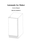
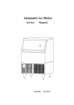
Automatic Ice Maker Service Manual MIM-75, MIM100, MIM130 1 Table of contents How the Icemaker works ---------------------------------------------3-10 Cooling System ------------------------------------------------------------------3 Water System ------------------------------------------------------------------ 4-6 Wiring Connections and Controller------------------------------ -----------7-9 Exploding Drawing -----------------------------------------------------------10-12 TroubleShooting ------------------------------------------------------- 13-17 Before Maintenance------------------------------------------------------------13 Basic Checking -----------------------------------------------------------------13 TroubleshootingGuide--------------------------------------------------------- 14-17 Adjustment and Replacement---------------------------------------------------- 18-20 Replace the controller---------------------------------------------------------- 18 Adjust the size of ice cube-----------------------------------------------------18 Replace the water pump--------------------------------------------------------19 Replace the water inlet valve------------------------------------------------- 19 Replace the compressor--------------------------------------------------------19 Replace the fan motor and fan blade-----------------------------------------20 Replace the hot gas valve, drier and evaporator----------------------------20 Spare parts list ---------------------------------------------------------21 IMPORTANT: The service manual is based on the user manual. Before servicing, please read user manual and service manual carefully. The service operation should be implemented by qualified technician. 2 How the Icemaker Works Please refer to the section “Operation of user manual” from page 14 to 17 . It describes clear how the icemaker makes ice and uses the water. There are 3 systems including Cooling System, Water System and Wiring Connection and Controller. Cooling System 3 ITEM NO 2 2.1 DESCRIPTION 4 5 9 10 11 Controller box Temperature sensor of the condenser Temperature sensor of the evaporator Wiring harness Drier & Fliter Condenser Multi-connection pipe(Copper) Hot gas solenoid valve 12 13 15 16 Capillary tube Hot gas tube Suction tube Compressor 17 18 18.1 18.2 49 Discharge tube Fan motor Fan motor support Fan blade Evaporator (Ice Mold) 2.2 During the ice-making stage, the hot gas solenoid valve is closed. The hot refrigerant gas is pumped out off compressor to condenser. The hot gas is cooled by fan forced air to warm liquid refrigerant after passing through the condenser. The drier & filter reduces the possible dirty and humidity in the refrigerant. The evaporator is cooled by the refrigerant. So ice can formed on the evaporator during water is sprayed to the evaporator. Low pressure refrigerant gas may go back compressor from the evaporator. During the ice harvest stage, the solenoid valve is open. The hot refrigerant gas is pumped out off compressor to evaporator through hot gas valve. As the hot gas is not cooled by the condenser, the refrigerant makes the evaporator (ice mold) warm. So some ice touching the evaporator is thawed. All of ice can slide down to the ice storage bin. Water System During the ice harvest stage, the water inlet valve will be powered to open. Water pump is powered off. Water is supplied by water supply pressure through Water valve outlet tube (No.34) to Evaporator(No.49). Then, water will fall to Water bin (N0.63). When, the water bin is full, water will overflow through the pipes to the drain pipe. During the ice-making stage, the water inlet valve will be closed. The water pump is powered on. water is pumped from the water bin to spray to the evaporator through the pipes (No.35, No.37) and pump (No.38). Most of water go back water bin. Some water is frozen on the evaporator step by step.. 4 5 ITEM NO 21 23 25 26 27 28 29 31 34 35 37 38 39 40 41 42 49 50 51 52 53 54 55 58 59 60 61 62 63 64 65 66 67 68 69 70 72 73 DESCRIPTION Downcomer Rubber of drain Connector of drain Multi-connection pipe Drain pipe Nut of water draining hole Water supply pipe Water inlet valve Water valve outlet tube Return pipe of pump Water outlet tube of pump Water pump Rubber of drain Syphon Tie-in of return pipe 2 Net of return pipe Evaporator (Ice Mold) Water level pipe Rubber gasket Net of return pipe Rubber gasket Rubber sprinkler Rubber sprinkler 1 Rubber sprinkler 2 Rubber sprinkler 3 Tie-in of return pipe 2 Slide way Small nozzle Small chock plug of sprinkler Sprinkler Flake of sprinkler Water bin Left flake Flake cover Right cover Tie-in of return pipe 1 Rubber gasket Net of return pipe Pole of flake cover Storage bin Ice cube full sensor 6 Wiring Connection : CIRCUIT DIAGRAM Circuit Description 1. Water Inlet Status As the icemaker is properly installed. when the machine is powered on, or wake up from Standby Status and Cleaning status, the machine works in the Water Inlet Stage. In this status, Water inlet valve and hot gas solenoid valve is powered on and water get in the water bin preparing for ice-making status. This status is set to 5 minutes and also helpful to protect the compressor avoiding restart within 5 minutes. At this status, the Red, Green, Yellow LEDs are light together. 2. Ice-making Status The compressor, motor fan and pump are power on. The water inlet valve and hot gas solenoid valve is shut down. When this green LED is lit, the unit is working in the ice making mode controlled by temperature probe on the evaporator. When the green LED is flashing, the unit is working in the time-lapse ice 7 making mode which determined by condenser temperature. 3. Ice Harvest Status The pump shut down and the hot gas valve is open, condenser fan is controlled by condenser temperature to avoid over heat, meanwhile water inlet valve is open to refill water trought for next cycle. Once the evaporator met a certain temperature, unit will switch to time-lapse harvest status and water pump is going to start in the last minitue. The Yellow LED indicates the ice harvest status. 4. Ice Full Status If the ice bin is filled with ice and the full sensor is covered, the machine will turn into ice full status. In this status, all the electric components shuts down. The RED LED indicates the status. 5. Cleaning Status When Clean button of controller is pressed, the machine turn to Cleaning Status. At this status, the pump and water inlet valve are powered on. Compressor, motor fan are powered off. The green and yellow LEDs flash together. To stop the cleaning mode, press the ‘Clean’ button again. MAJOR FUNCTIONS OF CONTROLLER 1. Completely automatic operation procedure. 2. When the ice storage bin is full of ice cubes, the machine will stop working automatically and start again after the ice cubes are taken out. 3. The different color of LED display different work mode. 4. Major fuse broken indicate, and stop working. 5. The motor fan is submitted to the ambient temperature. The Fan motor will stop working to keep the cooling system working in a good status if the ambiebt temperature is too low. 6. Smart control method. A probe and timer make the icemaker working always in a good status. 7. The compressor is protected by being restarted delaying 5 minutes. 8 Exploding Drawing 9 Item No. 2 2.1 2.2 2.3 2.4 3.1 3.2 4 5 7 8 9 11 11.1 12 16 18 18.1 20 27 28 29 31 32 38 45 46 48 49 54 58 59 60 61 63 64 65 66 73 Description Control box Temperature sensor of condenser Temperature sensor of evaporator 0.5A fuse of controller 15A fuse of controller Left foot Right foot Wiring harness Drier Power cord Power switch Condenser Hot gas valve coil Hot gas valve body Capillary tube Compressor Motor 5W Fan bladeφ200X28° Ice scoop Long drain pipe Nut of the draining hole(including the rubber gasket) Water supply pipe Water inlet valve Nut of the water inlet tube Water pump Door frame Door Door handle Evaporator(ice mold) Rubber of sprinkler Ice slideway Small nozzle Small plug of sprinkler Sprinkler Water bin Left flake Flake cover Right flake Ice full sensor 10 Troubleshooting ELECTRICAL SHOCK HAZARD Disconnect Electrical Power Before Beginning Removal of Parts Before Maintenance 1. Check out the user if the user uses a 115 Volt, 60Hz. AC only 15ampere electrical supply, and have properly grounded, ensure the maintainer against electrical shock. 2. Check out the leads loose? Turn off? Short circuit? If have such problems, foreclose in turn. Basic Checking The icemaker has some trouble, through the appearance phenomena judges. So the service technician must check it thoroughly, then maintain. Hearing Hearing the user 's depiction about the icemaker at using process and the phenomena. Try to understand what is the defect and how did the user operate the icemaker before calling for service. If the running sound is normal? Looking Check the pipe of cooling system, especially the welding point. If there is some oil, the gas is leak out so that no ice making or less ice produced. If the cycle of the ice making and harvest is normal? Check the water system, especially the connection, nut of water discharging hole. If there is some water leakage. Check if the water filter needs to be replaced. Check if the icemaker installed according to the user manual. Check if the icemaker needs to be cleaned. Touching Touch the hot gas pipe (with the evaporation weld), feeling the temperature. At the ice making stage, feeling cool. At the ice harvest stage, feeling hot. Touch the capillary tube (the drier nearby), feeling tepefaction. Troubleshooting Guide This troubleshooting guide in the user manual should be read before this guide. Be sure only when the trouble shooting in user manual can’t help you solve the problem, turn to this guide. 1.The machine does not make ice 11 Proble m kinds Check part point Plug Possible Cause or Socket Power switch Fuse Wiring connection Voltage The machin e don't Ice full operate sensor Ice full sensor wiring Electric component Controller Water supply tap Water supply pipe Water System Water line Water inlet valve Water pump Probable Correction The icemaker is unplugged. Socket is damaged The icemaker power switch turns to OFF. The fuse is blown. Some wiring connection is incorrect or loosed The voltage of the power supply is low. The ice full sensor is out of function(The icemaker will stop after it works 18 cycles) The ice full sensor is covered by something Some wiring is damaged Some electric component fail Plug the icemaker in. Water pump damages The room temperature is out the stated range, the water pump stop automatically. The lines of the water pump loose. The housing of water pump leaks. Replace water pump. Make the temperature returns within the stated range. Check and replace Turn the icemaker power switch to ON. Replace fuse. Check and re-connect Add manostat. Replace a new one. Clean and clear the sensor Replace a new one Find the controller, press the mode button to change the mode. It is helpful to judge which part is out of function The controller fail Replace a new one The water supply tap is Turn on the water supply turn off. tap. The water supply pipe Reconnect the water supply is not proper connected or pipe. maybe kinked Some water line leaks. Plug into again. Clean it, see user and care The water line blocks manual "ice making system cleaning" Water supply pressure is Adjust the water supply lower. pressure within the range of stated range. Water inlet valve is Check and re-connect loosed Plug into again Replace water pump. 12 Problem kinds The compresso r doesn't start or start frequency Check part or point Wiring connects The start relay/ther mal protect The startup coil / running coil Condenser Fan The Electronic controller Refrigeran t The compresso r run Capillary tube but no ice Vent Hot gas valve The Electronic controller 2.Low production Problem kinds Check part or point Refrigerant Condenser Cooling System The ambient temperature Possible Cause Probable Correction loose. Plug tightly, or replace. Be damaged. Replace the start relay/thermal protect of the compressor Be turnoff. Replace the compressor. The motor of the Replace the compressor. compressor is short circuit. The condenser may be dirty. The fan may be dirty or damaged The controller is damaged Clean the condenser. Clean or Replace the fan . Replace the Electronic controller. Add low side access valve, locate leak, Refrigerant leaks recover refrigerant, replace drier, evacuate completely and weigh in the data plate charge. Add low side access valve, recover Capillary tube is blocked refrigerant, replace hot gas valve, replace drier, evacuate and weigh in the nameplate charge. The vent is obstructed Clean the vent around the ice machine Hot gas valve damaged Replace The model of making ice Replace the Electronic doesn't turn to harvest. controller. vice versa. Possible Cause Refrigerant leaks partially The condenser may be dirty. The ambient temperature is high or too low Probable Correction Recharge. Clean the condenser. Check the ambient and air flow 13 Fan Hot gas valve Problem kinds Check part or point The fan is dirty or damaged Hot gas valve performance poor, leads to few ice is produced. Possible Cause The bin drain may be partially restricted. The water quality is too poor. The water Water line line blocks The silica gel tubes Silica gel distort, lead to block. tubes Tie-in return The tie-in return pipe pipe blocks. Bin drain Water System 3. Ice Cube is not OK Problem Check part kinds or point Condenser Cubes are too small The ambient temperature Electronic controller Refrigerant Electronic controller Cubes are too big Sensor The ambient and water temperature Water quality The cubes are partially formed--h ave ragged sides Small nozzle The room temperature Possible Cause The condenser is dirty or the air grills are covered The ambient temperature is too high. The setting temperature is high. Clean or replace Replace the hot gas valve Probable Correction Clean out the drain, check the installation. Using a filter apparatus installed in front of the water inlet valve. Make the silica gel tubes resile Clean screen, see user’s manual "interior cleaning", Probable Correction Clean the condenser. Leave space around the machine Adjust the ambient temperature. See the service manual "adjust the size of ice cubes" Refrigerant leaks Recharge. The setting See the service manual temperature of "adjust the size of ice Electronic controller cubes" is low. The sensor of Replace the sensor of temperature damages temperature. The ambient Adjust the temperature. temperature and water temperature is too low. The water quality is Using a water-soften / filter apparatus installed poor in front of the water inlet valve. Spraying is blocked Adjust the location of the by the ice slideway ice slideway. The room temperature Make the temperature is out the stated range, returns within the stated the water pump stop range. 14 The ice cubes shape deformity Sprinkler Problem kinds The ice cubes are incomplete while being dumped Check part or point Small nozzle Sprinkler Water bin Cubes are partially formed—a re white at the bottom Sprinkler pressure of spray Sprinkler The room temperature 4.Other problems Problem kinds Check part or point Earth line Clean the sprinkler, see the user's manual "interior cleaning" the root of the small Replace the small nozzle. nozzle have crack. The sprinkler clogged Possible Cause The sprinkler blocked. Probable Correction is Clean it. Not enough water in Check water the water bin. supply—filter may be restricted. The water line may be blocked The sprinkler pressure Check the silica gel tubes of spray isn't enough. distort, lead to block. Check the tie -in return The sprinkler is blocked. The room temperature is out the stated range, the water pump stop automatically. Possible Cause The earth line isn't in the socket. The body Lines The lines are is creepage. electrified Electric The electric component component is creepage, the water The rigidity of the Scales quality water quality is too occur high. frequently inside the machine Water inlet The noise of the water valve inlet valve pipe may be blocked. Clean it. Make the temperature returns within the stated range. Probable Correction Please use the socket meeting the standard. Adjust, reconnect /replace lines Replace this electric component. Using a water-soften apparatus installed in front of the water inlet valve. Replace the water inlet valve. 15 Noise during operation is big Spring of the internal compressor Water pump Pipeline system Feet Fan motor Problem kinds Check part or point The spring of the internal compressor Replace the compressor. drops. The noise of the water pump Pipeline system resonate The feet are not leveled The fan motor loose, the clearance of the rotor is bigger, the fan blade turns back Possible Cause A few water drops to the floor when you The operation open the door to take out ice from ice storage bin. Water is leaking out Water supply Water supply the unit connection connection leaking. Nut of the water drain hole Drain pipe connection The water quality Nut of the water drain hole leaking. Replace the water pump. Clear pipeline system Level and lock the feet. Relocate the fan motor / replace Probable Correction Normal condensation on the door or some water together with ice. Take care when you take out ice. Tighten fitting. See Connecting the water line. Tighten fitting. See “Connecting the Water Line” Tighten fitting. See connecting the drain. Using a filter apparatus installed in front of the water inlet valve. Drain pipe connection leaking. The water quality is too poor. The water line blocks The silica gel tubes Make the silica gel tubes The sprinkler Silica gel distort, lead to block. resile pressure of tubes spray isn't Tie-in return The tie -in return pipe Clean screen, see user’s enough pipe manual "interior blocks. cleaning", Water pump The lines of the water Plug into again pump loose. The Water pump sprinkler Water pump damages Replace water pump. doesn't The room temperature Make the temperature The room is out the stated range, returns within the stated spray temperature the water pump stop range. Clean it, see user and care The water line blocks manual "ice making Water line system cleaning" The downcome The rubber of drain Make the silica gel tube Rubber of r doesn't distort. resile. drain leak 16 Hot gas valve The hot gas valve is poor, The hot gas valve damage Harvesting The ice mold is Ice mold of ice is dirty, or polishing the difficult degree is poor. evaporator Refrigerant Refrigerant leaks The ambient The ambient and and water water temperature is temperature too low ice cubes size The size is too big. Problem kinds Check part or point Sensor of temperature Hot gas valve The evaporator is hot more Refrigerant than 5 Electric minutes controller The evaporator Hot gas valve is not hot in the ice harvest mode Possible Cause Replace the hot gas valve Replace the hot gas valve Clean the ice mold, or replace the evaporator. Recharge Adjust the temperature. See the adjust of ice cube size. Probable Correction Sensor of temperature breaks(damages) Hot gas valve performance poor Replace sensor of temperature Replace the coil of hot gas valve if only because of the coil. Refrigerant leaks Recharge The electric controller Check the controller is wrong Hot gas valve Replace the coil of hot performance poor or gas valve if only because break of the coil. The lines of the hot Plug into again gas valve loose. 17 Adjustment and Replacement Replace Controller, fuse and the sensor of temperature ELECTRICAL SHOCK HAZARD Disconnect Electrical Power Before Beginning Removal of Parts Remove the front cover, top cover, right side, Locate the Electronic controller, Unplug the lines with the wiring harness, pull out the sensors of temperature (one at the evaporator, another at the condenser), loosen the screws of rooting the Electronic controller, replace a new one. Reverse the above step to replace. If you need replace the fuse, open the front cover of the control box, you will find the figure. According the figure, take out the fuse1, replace a new one. Reverse the above step to reassemble. If you need replace the sensors of temperature, pull out the sensor of temperature, open the rear of the controller box, pull out the other side, replace a new one. Reverse the above step to reassemble. Adjust the size of ice cube 1. Press and hold the “Clean” button and the “Mode” button together for at least 3 seconds. The unit will enter the Ice Size Adjustment mode. The “HARVEST” LED (yellow) will be blinking continuously during the ice size adjustment. 2. While in the Ice Size Adjustment mode, press the “Clean” button or the “Mode” button for the desired ice size. Smaller ice setting: By pressing the “Clean” button, you can decrease the size of the ice cubes. The “ICE” LED (green) will flash as you lower the ice size and will finally be blinking at the setting of smallest ice size. Larger ice setting: By pressing the “Mode” button, you can increase the size of the ice cubes. The “BIN FULL” LED (red) will flash as the larger size is set and will blink when the setting of largest ice size 18 has been reached. After 10 seconds without any operation, the unit will return to the previous mode. NOTE: During the ice size adjustment, the “BIN FULL”, “ICE” and “HARVEST” LEDS blinking all at once indicate that the unit is in the default factory setting of the ice size. Replace the water system components Please see the water system drawing. The water leakage should be checked after this kind of operation Unscrew the nut of the water draining hole, drain off the waste water to some container, then screw the nut on tightly when the waste water is fully drained off. 1. Replace the water pump Disconnect electrical power. Remove the rear cover Unplug the lines connector with the water pump, the water outlet tube of pump and the water inlet tube of pump. Loosen the screws, replace a new one. Reverse the above step to reassemble. 2.Replace the water inlet valve If the water inlet valve does not work at all, or does not shut off tightly, it should be replaced. Unplug or disconnect electrical power, Loosen the water supply pipe, remove the water panel, loosen 2 screws holding the water inlet valve, unplug the lines and loosen the water valve outlet tube, Replace a new one, reverse the above step to reassemble. Replace the cooling system components Replace the condensing components, See Figure “cooling system” 1.Replace the compressor and the compressor kit (includes relay, thermal protect). If only need replace the compressor kit, remove the rear, locate the compressor, take the clip, open the cover, replace the wrong, Reverse the above step to reassemble. 19 If need replace the compressor, remove the rear cover, and left side, locate the compressor, Unplug the lines and taken out the earth line, add low side access valve, open the Process/Suction, evacuate refrigerant, take out the compressor, replace a new one, joint together, then recover refrigerant, weigh in the nameplate charge. Reverse the above step to reassemble. 2. Replace the fan motor and fan blade. Remove the top cover, rear and left side, locate the fan motor, unplug the lines connecting with the fan motor, loosen the screws of holding fan motor bracket, Replace a new one, If only need replace the fan blade, loosen the screws holding the fan blade, taken out the damaged, replace a new one, Reverse the above step to reassemble. 3. Replace the hot gas valve, drier and evaporator. Remove the rear, top cover and the left side Locate the drier and hot gas valve, add low side access valve, recover refrigerant, replace the drier and hot gas valve, evacuate and weigh in the nameplate charge. Reverse the above step to reassemble. If need replace the evaporator, Remove the rear, top cover, locate the evaporator, add low side access valve, weld open the two welds, replace a new one. Recover refrigerant, evacuate and weigh in the nameplate charge. Reverse the above step to reassemble. 20 Spare parts list ITEM NO 2 2.1 CODE 1854200302 DESCRIPTION Control box Temperature sensor of condenser 2.2 1851700401 1851700201 3.1 1880014701 Left foot 3.2 1880014801 Right foot 4 1853700406 Wiring harness 5 1880007500 Drier 7 1853110500 Power cord 8 1854000101 Power switch 9 1880012905 Condenser 11 1854703321 11.1 1854703310 Hot gas valve coil Hot gas valve body 12 1805000200 Capillary tube 16 1858400100 Compressor 18 1858200601 Motor 5W 18.1 1860700100 Fan bladeφ200X28° 20 1864800100 Ice scoop 27 1864506100 Long drain pipe 28 29 1864538100 1811306020 31 1854703200 Water inlet valve 32 1864529100 Nut of the water inlet tube 38 1858900600 Water pump 45 1864806202 Door frame 46 1864806601 Door 1 48 1861702202 Door handle 49 1880024203 Evaporator(ice mold) Temperature sensor of evaporator Nut of the draining hole(including the rubber gasket) Water supply pipe 21 54 1864803400 Rubber of sprinkler 58 1861700704 Ice slideway 59 1864612100 Small nozzle 60 1864603200 Small plug of sprinkler 61 1861400700 Sprinkler 63 1864801701 Water bin 64 1861703200 Left flake 65 1864600200 Flake cover 66 1861703300 Right flake 73 1855501200 Ice full sensor 1854800200 0.5A fuse of controller 1854800300 15A fuse of controller 22