1
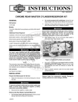
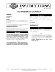
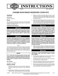
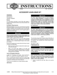
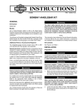
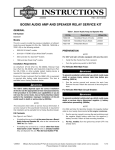
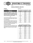
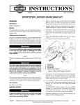
-J04400
REV. 2007-05-07
SOFTAIL EXTENDED REACH BRAKE LINE KIT
GENERAL
Kit Number
44970-07, 44972-08
Remove brake line components carefully. Damage to
seating surfaces can cause leakage. (00320a)
Models
6.
For model fitment information, please see the P&A Retail Catalog or the Parts and Accessories section of www.harleydavidson.com (English only).
Install Brake Line
Remove brake line following the instructions in the Service
Manual.
Additional Parts
NOTE
These kits CANNOT be used with the following accessories:
•
Engine guard (Part Number 49200-07)
•
Rear master cylinder cover (Part Number 45665-01)
In addition to the parts from the kit, LOCTITE® 243 (blue)
Threadlocker and Sealant (Part Number 99642-97), HarleyDavidson Wheel Bearing Grease (Part Number 99855-80) and
DOT 4 Brake Fluid (Part Number 99953-99A) is also required
for installation.
For accessories and kit part numbers see your local HarleyDavidson dealer, www.harley-davidson.com or your HarleyDavidson Genuine Motor Accessories and Parts catalog.
Be sure that no lubricants or fluids get on tires, wheels or
brakes when changing fluid. Traction can be adversely
affected, which could result in loss of control of the
motorcycle and death or serious injury. (00047d)
1.
Connect the stoplamp switch and install the new rear brake
line from the brake line kit following the instructions in the
Service manual.
2.
Bleed the brakes following the instructions in the Service
Manual.
is05042
NOTE
This instruction sheet references Service Manual information.
A Service Manual for your model motorcycle is required for
this installation and is available from a Harley-Davidson Dealer.
1
2
4
Kit Contents
See Figure 4 and Table 1.
INSTALLATION
3
5
Prepare the Motorcycle
1.
If equipped with saddlebags, remove the saddlebags following the instructions in the Service Manual.
2.
Remove the seat following the directions in the Owner's
Manual.
To prevent accidental vehicle start-up, which could cause
death or serious injury, disconnect negative (-) battery
cable before proceeding. (00048a)
3.
Disconnect the negative battery cable.
4.
Secure motorcycle in upright position.
5.
Disconnect the harness from the stoplamp switch (3).
-J04400
1.
2.
3.
4.
5.
Rear brake line mounting fastener
Rear brake line
Stoplamp switch
Terminals
Alignment marks
Figure 1. Brake Line Bracket and Stoplamp Switch
1 of 3
Use denatured alcohol to clean brake system components.
Do not use mineral-based solvents (such as gasoline or
paint thinner), which will deteriorate rubber parts even
after assembly. Deterioration of these components can
cause brake failure, which could result in death or serious
injury. (00291a)
is05041
1
Direct contact of D.O.T. 4 brake fluid with eyes can cause
irritation. Avoid eye contact. In case of eye contact flush
with large amounts of water and get medical attention.
Swallowing large amounts of D.O.T. 4 brake fluid can cause
digestive discomfort. If swallowed, obtain medical attention. Use in well ventilated area. KEEP OUT OF REACH OF
CHILDREN. (00240a)
NOTE
The sight glass enables the rider to visually check the brake
fluid level without removing the master cylinder cover. When
the reservoir is full, the sight glass is dark. As the fluid level
drops, the glass lightens up to indicate this condition to the
rider.
6.
Add brake fluid, if necessary, following the instructions in
the Owner's Manual.
Return to Service
1. Brake line clamp
Figure 2. Brake Line Clamp
1.
For models equipped with saddlebags: Install the saddlebags following the instructions in the Service Manual.
2.
Connect the negative battery cable.
After installing seat, pull upward on seat to be sure it is
locked in position. While riding, a loose seat can shift
causing loss of control, which could result in death or
serious injury. (00070b)
3.
3.
See Figure 2. Install the clamp (1) around the brake line
and tighten fastener to 30 in-lb (3.4 Nm)
4.
Verify that the brake line runs parallel to the rear of the
brake lever bracket and that the brake line does not rub
against any part of the bracket.
5.
See Figure 3. Install the cable straps at locations (1).
Be sure that no lubricants or fluids get on tires, wheels or
brakes when changing fluid. Traction can be adversely
affected, which could result in loss of control of the
motorcycle and death or serious injury. (00047d)
NOTE
Hydraulic brake fluid bladder-type pressure equipment can be
used to fill brake master cylinder through the bleeder valve.
Remove the master cylinder reservoir cover so that the system
cannot pressurize. Do not use pressure bleeding equipment
when the hydraulic system is sealed with master cylinder
reservoir cover and gasket in place.
Install the seat following the instructions in the Owner's
Manual.
The jiffy stand locks when placed in the full forward (down)
position with vehicle weight on it. If the jiffy stand is not
in the full forward (down) position with vehicle weight on
it, the vehicle can fall over which could result in death or
serious injury. (00006a)
Be sure jiffy stand is fully retracted before riding. If jiffy
stand is not fully retracted, it can contact the road surface
causing a loss of vehicle control, which could result in
death or serious injury. (00007a)
4.
Verify jiffy stand operation.
5.
With the ignition/light key switch turned to IGNITION,
actuate the rear brake pedal to verify operation of the
brake lamp.
After repairing the brake system, test brakes at low speed.
If brakes are not operating properly, testing at high speeds
can cause loss of control, which could result in death or
serious injury. (00289a)
6.
-J04400
Test ride the motorcycle. If the brake feels soft, repeat the
rear brake bleeding procedure.
2 of 3
is05046
1
1
1. Cable strap locations
Figure 3. Cable Strap Location
SERVICE PARTS
is05040
3
2
1
6
4
7
5
Figure 4. Service Parts: Extended Reach Forward Control Brake Line
Table 1. Service Parts
Item
Description (Quantity)
Part Number
1
Brake line assembly, chrome (2007 models)
Not Sold Separately
2
Brake line assembly, chrome (2008 models)
Not Sold Separately
3
Cable strap (2)
10006
4
Gasket, brake line (4)
41731-01
5
Clamp, brake line (2007 models)
10106
Clamp, brake line (2008 models)
10059A
6
Lockwasher, #8
7015
7
Screw, #8-32x0.38
94634-99
-J04400
3 of 3