1
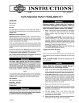
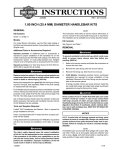
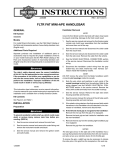
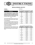
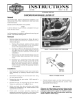
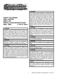
-J03292
REV. 2006-07-28
BOMBAY HANDLEBAR KIT
GENERAL
Kit Number
55835-05A
Models
Ask a Harley-Davidson dealer or refer to the latest HarleyDavidson Genuine Motor Accessories and Genuine Motor Parts
catalog to determine if this handlebar can be installed on your
motorcycle.
The rider's safety depends upon the correct installation
of this kit. Use the appropriate service manual procedures.
If the procedure is not within your capabilities or you do
not have the correct tools, have a Harley-Davidson dealer
perform the installation. Improper installation of this kit
could result in death or serious injury. (00333a)
NOTE
This kit does not fit models equipped with Heated Hand Grips,
Softail Nacelle Kit (Part Number 67907-96), Hydraulic Clutch
Kits, handlebar mounted gauges or the Road Tech® Radio.
This instruction sheet references Service Manual information.
A Service Manual for your model motorcycle is required for
this installation and is available from a Harley-Davidson Dealer.
Additional Parts or Accessories Required
Kit Contents
The integrated gauge housing accepts most 2-5/8 in. (66.7
mm) diameter Mini-Tach gauges, sold separately.
See Figure 4 and Table 1.
Separate purchase of additional parts or accessories may be
required for proper installation of this handlebar kit on your
model motorcycle. Refer to the latest Harley-Davidson Genuine
Motor Accessories and Genuine Motor Parts catalog for a list
of required parts or accessories for your model.
Loctite® 271 (Red) Threadlocker and Sealant (H-D Part Number
99671-97) is required for the proper installation of this kit.
Fresh, uncontaminated brake fluid will also be needed. Refer
to your Owner's Manual or the Service Manual for this year
and model motorcycle to determine the correct brake fluid for
this vehicle.
Replace brake line gaskets. Re-using original gaskets can
cause brake failure and loss of vehicle control, which could
result in death or serious injury. (00318a)
For models that re-use the original brake line, the two brakeline gaskets found at each banjo fitting must be replaced.
Refer to the appropriate Parts Catalog or see a HarleyDavidson dealer for the correct part numbers.
Motorcycles equipped with a glued left-side hand grip will also
require a new grip, sold separately. Refer to the Parts Catalog
for replacement stock hand grips.
Ask a Harley-Davidson dealer about the selection of Genuine
Motor Accessory hand grips that are available.
-J03292
INSTALLATION
Preparation
To prevent accidental vehicle start-up, which could cause
death or serious injury, disconnect battery cables (negative
(-) cable first) before proceeding. (00307a)
Disconnect negative (-) battery cable first. If positive (+)
cable should contact ground with negative (-) cable connected, the resulting sparks can cause a battery explosion,
which could result in death or serious injury. (00049a)
1.
Refer to the Service Manual and follow the instructions to
remove the seat and disconnect the battery cables, negative cable first. Retain all seat mounting hardware.
When servicing the fuel system, do not smoke or allow
open flame or sparks in the vicinity. Gasoline is extremely
flammable and highly explosive, which could result in
death or serious injury. (00330a)
2.
Loosen the fuel tank. Refer to FUEL TANK REMOVAL in
the appropriate section (Carbureted or EFI Engine) of the
Service Manual.
1 of 7
end of the tubing over the caliper bleeder valve. Place the
free end of the tubing into a suitable container.
Direct contact of D.O.T. 5 brake fluid with eyes can cause
eye irritation, swelling, and redness. Avoid eye contact.
In case of eye contact flush with large amounts of water
and get medical attention. Swallowing large amounts of
D.O.T. 5 brake fluid can cause digestive discomfort. If
swallowed, obtain medical attention. Use in well ventilated
area. KEEP OUT OF REACH OF CHILDREN. (00144a)
Direct contact of D.O.T. 4 brake fluid with eyes can cause
irritation. Avoid eye contact. In case of eye contact flush
with large amounts of water and get medical attention.
Swallowing large amounts of D.O.T. 4 brake fluid can cause
digestive discomfort. If swallowed, obtain medical attention. Use in well ventilated area. KEEP OUT OF REACH OF
CHILDREN. (00240a)
D.O.T. 4 brake fluid will damage painted and body panel
surfaces it comes in contact with. Always use caution and
protect surfaces from spills whenever brake work is performed. Failure to comply can result in cosmetic damage.
(00239b)
•
If D.O.T. 4 brake fluid contacts painted surfaces, flush
IMMEDIATELY with clear water.
is00298
4.
Open the bleeder valve about one-half turn and pump the
front-brake hand lever to drain the fluid out of the front
brake system. Do not re-use brake fluid.
Original Handlebar Removal
NOTE
Cover the front fender and the front of the fuel tank with clean
shop towels to prevent scratching. Damage to the finish could
result.
Remove brake line components carefully. Damage to
seating surfaces can cause leakage. (00320a)
1.
Carefully make note of the front brake line routing and the
orientation of the banjo fittings. Disconnect the brake line
from the front brake caliper and the front brake master
cylinder assembly. Save the banjo bolts, but discard the
two brake-line gaskets found at each banjo fitting. See
FRONT BRAKE MASTER CYLINDER in the Service
Manual.
2.
Remove the old brake line from the motorcycle.
NOTE
For models with handlebar-mounted turn signals, remove the
plastic wiring retainer clips that secure the turn signal harnesses
to the handlebar.
3.
Using a T27 TORX® drive head, remove the front-brake
master cylinder and clutch-lever assemblies from the
handlebar.
4.
Refer to CLUTCH HAND CONTROL: REMOVAL in the
Service Manual, and follow the instructions to disconnect
the clutch cable from the clutch lever.
1
If the clutch cable is being replaced, disconnect the
clutch cable from the side cover, and remove the cable
from the vehicle.
NOTE
Molex connectors are used for the handlebar control wiring on
2007 and later models. 2006 and earlier vehicles use Deutsch
connectors. Refer to the MOLEX ELECTRICAL CONNECTORS
or DEUTSCH ELECTRICAL CONNECTORS section of the
Service Manual for disconnection and re-connection procedures.
Before disconnecting the handlebar control wiring, note the
wire routing.
5.
Disconnect the handlebar control wiring from the gray and
black 6-way main harness connectors under the fuel tank.
NOTE
Before disconnecting the turn signal wiring, note turn signal
wire routing.
1. Caliper bleeder valve
6.
For vehicles with handlebar-mounted turn signals, separate
the 6-way turn signal connector halves.
7.
For vehicles with handlebar-mounted turn signals, install
new front turn signal mounting brackets (sold separately)
per the instructions in that kit.
8.
Refer to HANDLEBAR SWITCHES: RIGHT HANDLEBAR
CONTROLS section of the Service Manual for removal of
Figure 1. Draining Brake Fluid
3.
Bleed the brake fluid from the front brake.
See Figure 1. Open the bleeder nipple cap on the front
brake caliper. Obtain a length of plastic tubing. Install one
-J03292
2 of 7
the right-side switch housing assembly and harness. This
is necessary to access the throttle cables.
9.
Models with handlebar-mounted turn signals: Note the
wire colors and positions in each cavity of the Multilock
socket housing leading from the turn signals. Refer to
the wiring diagram and the AMP MULTILOCK ELECTRICAL CONNECTORS section in the Service Manual.
Remove the wires from the socket housing.
Refer to the THROTTLE CONTROL section of the Service
Manual to disconnect the throttle cables from the existing
right grip/ throttle sleeve assembly.
10. Refer to the LEFT HANDLEBAR CONTROLS section of
the Service Manual for removal of the left-side switch
housing assembly and wire harness.
11. See Figure 2. Remove and discard the screws (1) that
fasten the handlebar upper clamp or clamps (2) to the
risers (3). Discard the clamps. Remove the handlebar (4)
from the motorcycle.
12. If the left-side hand grip is not glued to the handlebar:
Remove the hand grip and set it aside for installation to
the new handlebar.
is00332
1
1
15. Use tape to wrap the wire terminal ends from each source
to make separate leaders. Wrap each leader tight enough
to enter the grommet hole and pass easily through the
new handlebar.
New Handlebar Wiring
1.
Remove the plastic wiring retainer clips that secured both
switch harnesses to the original handlebar.
2.
See Figure 4. Slide one large grommet (2) onto each of
the switch-wire bundles, positioning the grommet close to
the switch end.
3.
For models WITHOUT handlebar-mounted turn signals,
proceed to Step 8.
For 2006 and later FXDB and FXDWG models, proceed
to Step 4.
2
2
3
For models WITH handlebar-mounted turn signals,
EXCEPT 2006 and later FXDB and FXDWG models,
slide one small grommet (3) onto each of the turn-signal
wire bundles, positioning the grommet close to the turn
signal end.
5
FXSTD
4
4.
Apply a light coat of liquid soap, window cleaner, or allpurpose lubricant such as WD-40®, to the right-side turn
signal wire bundle.
5.
For 2006 and later FXDB and FXDWG models: Gently
feed the right-side turn-signal wire leader into the small
round grommet on the underside of the right-side lower
switch housing. Repeat Steps 4 and 5 for the left-side turn
signal wires, then proceed to Step 8.
3
5
1.
2.
3.
4.
5.
Clamp screw (4)
Clamp (2 on FXSTD, 1 on others)
Handlebar riser (2)
Handlebar
Riser attaching screw (2)
For all other models: Gently feed the right-side turnsignal wire leader into the small round grommet hole near
the right-side end of the new handlebar and toward the
center of the bar.
Figure 2. Handlebar Clamps and Risers
NOTE
Make note of the installed sequence of the riser attaching
hardware to ensure correct re-assembly.
13. Remove and discard the stock handlebar risers. Save the
remaining hardware for later installation.
NOTES
2007 and later models use Molex connectors. 2006 and earlier
vehicles use Deutsch connectors. Refer to MOLEX or
DEUTSCH ELECTRICAL CONNECTORS in the Service
Manual for terminal removal and re-installation procedures.
DO NOT remove the wires from the Molex or Deutsch handlebar switch connector pin housings under the fuel tank.
Models with handlebar-mounted turn signals: DO NOT
remove the wires from the Multilock connector pin housing
under the fuel tank.
Carefully pull the wires through hole in handlebar to prevent stripping the wires. Stripped wires can cause short
circuits and damage vehicle electrical components, which
could cause loss of vehicle control resulting in death or
serious injury. (00418b)
6.
Pull the taped end of the wire bundle through the wire-exit
hole in the riser.
7.
Repeat Steps 4 through 6 for the left-side turn signal wires,
pulling the taped end of the wire bundle through the lower
wire-exit hole in the riser.
8.
Apply a light coat of liquid soap, window cleaner, or allpurpose lubricant to the right-side switch wire bundle.
14. Note the wire colors and positions in each cavity of the
socket housings leading from the switches. Refer to the
wiring diagram and the ELECTRICAL CONNECTORS
section in the Service Manual. Remove the wires from the
socket housings.
-J03292
3 of 7
NOTE
The round turn-signal wiring grommets are an extremely tight
fit. Use a twisting motion to avoid damaging the grommets.
is03096
1
13. For models WITH handlebar-mounted turn signals,
EXCEPT 2006 and later FXDB and FXDWG models,:
Insert the turn-signal grommets (3) into place in the turnsignal wire holes in the handlebar.
14. Loosely fasten the brake-lever and clutch-lever clamps to
the new handlebar.
15. Loosely fasten the handlebar-switch housings to the new
handlebar.
16. Obtain the two larger pieces of heat shrink tubing (5) from
the kit. Slide one piece of the tubing over the end of the
wire bundle or bundles exiting each handlebar riser.
3
3
2
1. Upper switch housing screw
2. Lower switch housing screw
3. Pinch points
Figure 3. Switch-Housing Wire Routing (Right-Side
Housing Shown)
Wiring in the switch housings must be routed exactly as
shown. Pinch points in the switch housings can shortcircuit or sever wires, which could cause loss of control
resulting in death or serious injury. (00415b)
9.
See Figure 3.
For 2006 and later FXDB and FXDWG models: Route
the switch wire and turn signal wire bundles through the
switch housing as shown. Gently feed the wire bundles
into the oblong switch wire hole near the right-side end of
the handlebar, and toward the center of the bar.
For all other models: Route the switch wire bundle
through the switch housing as shown. Gently feed the wire
bundle into the oblong switch wire hole near the right-side
end of the handlebar, and toward the center of the bar.
17. Remove the tape from the ends of the wire bundles.
18. Check for electrical continuity between the handlebar and
each wire in the wire bundles. Continuity would indicate
a short circuit, which would require examination of the
wires and routing in the switch housing.
Wires exiting the bottom center of the handlebar must be
protected from wear with heat-shrink tubing at the wireexit hole on the handlebar. Failure to protect wires with
shrink tubing can cause short-circuits or severed wires,
which could cause loss of vehcle control resulting in death
or serious injury. (00432b)
NOTE
The heat-shrink tubing on the wire bundles exiting the handlebar risers must be installed to protect the wires from damage
and short circuits at the wire-exit holes in the risers.
19. Position the heat-shrink tubing (installed on the wire bundles in Step 16) in the area of the wire-exit holes in the
handlebar risers.
Be sure to follow manufacturer's instructions when using
the UltraTorch UT-100 or any other radiant heating device.
Failure to follow manufacturer's instructions can cause a
fire, which could result in death or serious injury. (00335a)
•
Avoid directing heat toward any fuel system component. Extreme heat can cause fuel ignition/ explosion
resulting in death or serious injury.
•
Avoid directing heat toward any electrical system
component other than the connectors on which heat
shrink work is being performed.
•
Always keep hands away from tool tip area and heat
shrink attachment.
10. Pull the taped end of the wire bundle through the wire-exit
hole at the center of the handlebar.
11. Repeat Steps 8 through 10 for the left-side handlebar
switch wires, pulling the taped end of the wire bundle
through the lower wire-exit hole in the riser.
Grommets in each of the wiring holes in the handlebar
must remain in position after routing the wiring through
the handlebar. Operation without the grommets in place
can damage wires, causing a short circuit which could
result in death or serious injury. (00416d)
12. See Figure 4. Insert the switch-wire grommets (2) into
place in the switch-wire holes in the handlebar.
-J03292
20. Use a heat gun or suitable radiant-heating device to shrink
the heat-shrink tubing to the wire bundles.
New Handlebar Installation
1.
Apply two drops of Loctite® 271 (Red) Threadlocker and
Sealant to the threads of each riser bolt (saved earlier).
Install the new handlebar onto the upper fork bracket using
the saved hardware in the same sequence as removed.
Tighten the riser bolts to 25-30 ft-lbs (34-41 Nm).
4 of 7
2.
Route the switch wire bundles down through the large oval
opening in the upper fork bracket.
3.
Follow the routing noted in the disassembly steps (left
switch wire bundle to left side of frame; right switch wire
bundle to right side of frame) until the wires reach the
switch-wire pin housings. Install any clips or wire guides
saved in disassembly.
NOTE
Molex connectors are used for the handlebar control wiring on
2007 and later models. 2006 and earlier vehicles use Deutsch
connectors. Refer to the MOLEX ELECTRICAL CONNECTORS
or DEUTSCH ELECTRICAL CONNECTORS section of the
Service Manual for re-connection procedures.
4.
Refer to the notes made during the removal steps, and
the wiring diagram and correct ELECTRICAL CONNECTORS section in the Service Manual. Insert each socket
terminal from the left-side wire bundle into the correct
cavity of the gray socket housing removed earlier.
5.
Insert each socket terminal from the right-side wire bundle
into the correct cavity of the black socket housing removed
earlier.
6.
Connect the gray socket housing to the gray 6-way pin
housing under the left side of the fuel tank. Connect the
black socket housing to the black 6-way pin housing under
the right side of the tank.
7.
For models with handlebar-mounted turn signals:
a.
Route both turn signal wires down through the large
oval opening in the center of the upper fork bracket.
b.
Follow the routing noted earlier to the 6-way turn
signal pin housing under the right side of the fuel tank.
c.
Refer to the notes made during the removal steps,
and the wiring diagram and AMP MULTILOCK
ELECTRICAL CONNECTORS section in the Service
Manual. Insert each socket terminal leading from the
turn signals into the correct cavity of the Multilock
socket housing removed earlier.
d.
8.
Install the clips and/ or wire guides saved earlier.
Connect the 6-way AMP socket housing to the main harness pin housing under the fuel tank.
When servicing the fuel system, do not smoke or allow
open flame or sparks in the vicinity. Gasoline is extremely
flammable and highly explosive, which could result in
death or serious injury. (00330a)
9.
Re-install the fuel tank. Refer to FUEL TANK-INSTALLATION in the appropriate section (Carbureted or EFI Engine)
of the Service Manual.
NOTE
For FXDWG models only: Route the throttle cables between
the upper fork tubes to the right of the headlight.
10. Refer to RIGHT HANDLEBAR SWITCH: INSTALLATION
in the Service Manual, and follow the instructions given
to install the throttle control cables and a new (purchased
separately) or original right grip/ throttle sleeve assembly.
-J03292
11. Adjust the position of the switch housing and the brake
lever assembly on the handlebar for rider comfort and
posture. The brake master cylinder must be horizontally
level.
NOTE
Tighten the top brake lever clamp screw before tightening the
bottom screw.
12. Use a T27 TORX drive head to tighten first the top, then
the bottom brake-lever clamp screws to 71-80 in-lbs (8.09.0 Nm).
NOTE
Tighten the lower switch housing screw before tightening the
upper screw. This will leave any gap in the switch housing at
the front for best appearance.
13. Use a T25 TORX drive head to tighten first the lower, then
the upper switch housing screws to 35-45 in-lbs (4.05.1 Nm).
14. Verify that the right grip/ throttle sleeve rotates and returns
freely and does not bind on the handlebar or switch
housing.
NOTE
If the handlebar grips are patterned, align the pattern on the
left grip with the pattern on the right grip while the throttle is in
the fully closed position.
15. Install a new (purchased separately) or original handlebar
grip on the left end of the new handlebar according to the
handlebar grip instruction sheet or the LEFT HAND GRIP,
INSTALLATION instructions in the Service Manual.
16. Refer to LEFT HANDLEBAR SWITCH: INSTALLATION
in the Service Manual. Adjust the positions of the switch
housing and the clutch lever assembly on the handlebar
for rider comfort and posture.
17. Use a T27 TORX drive head to tighten first the top, then
the bottom clutch-lever clamp screws to 71-80 in-lbs (8.09.0 Nm).
18. Use a T25 TORX drive head to tighten first the lower, then
the upper switch housing screws to 35-45 in-lbs (4.05.1 Nm).
19. See Figure 4. Attach the tachometer mounting bracket (7)
to the handlebar tie bracket (A) with the chrome sockethead screws (11) from this kit.
20. Obtain a 2-5/8 in. Mini Tach Kit (sold separately). Insert
the rubber isolator from the tach kit onto the tachometer
mounting bracket.
21. Mount the tachometer to the tachometer mounting bracket.
22. Mount the tachometer to the tach cover (6) using the
standoff (9) and chrome flat head screw (10) from this kit.
23. Mount the gasket (8) to the tach cover.
NOTE
Refer to the Warning in the New Handlebar Wiring section of
these instructions. Use a heat gun or suitable radiant-heating
device to shrink the heat-shrink tubing to the Mini Tach wiring
in the area of the wire-exit hole in the handlebar riser.
24. Use the small diameter heat shrink tube (4) from this kit
to protect the Mini Tach wiring, and follow the instructions
5 of 7
provided in the Mini Tach Kit to make the electrical connections to the vehicle.
FINAL ASSEMBLY
Replace brake line gaskets. Re-using original gaskets can
cause brake failure and loss of vehicle control, which could
result in death or serious injury. (00318a)
Avoid leakage. Be sure gaskets, banjo bolt(s), brake line
and caliper bore are clean and undamaged before
assembly. (00321a)
1.
2.
Obtain a new Brake Line Kit (sold separately). Carefully
inspect the new brake line for damage or defects, and
replace the brake line if damaged. Install the brake line
per the Service Manual instructions or the instructions
included with the Brake Line Kit.
Bleed the brakes. See BLEEDING HYDRAULIC BRAKES
in the Service Manual.
Be sure that all lights and switches operate properly before
operating motorcycle. Low visibility of rider can result in
death or serious injury. (00316a)
2.
Turn the Ignition/ Light Key Switch to IGNITION, but do
not start the motorcycle. Test each handlebar switch for
proper operation.
3.
For 2005 and earlier FXDWG models:
Be sure plug in lower forward section of rear fender is
installed. Operation without plug installed could allow tire
contact with wiring harness. Tire contact with wiring harness can cause wire damage, which could result in death
or serious injury. (00456b)
•
Inspect the lower forward section of the fender inside
the rear wheel well. A three-inch (76 mm) square hole
in the fender should be covered with a rubber plug.
•
If the plug is damaged, loose or missing, it MUST be
replaced (Part Number 59150-90, available from a
Harley-Davidson dealer). Without this plug in place,
the wire harness could come out of the opening and
contact the rear tire, causing rear lighting failure or
other serious electrical problems.
4.
For ALL models: Turn the handlebar to the left and right
steering stops, testing the handlebar control functions at
each stop.
5.
Apply the front brake hand lever to test operation of the
brake lamp.
6.
Refer to the Service Manual, and follow instructions to
install the seat.
NOTE
For FXDB and FXDWG only, install a clutch cable guide kit
(sold separately) along with the clutch cable.
3.
Re-install the clutch cable to the clutch lever or install a
new clutch cable (sold separately) per the CLUTCH HAND
CONTROL instructions in the Service Manual.
SAFETY CHECK
Be sure that steering is smooth and free without interference. Interference with steering could result in loss of
vehicle control and death or serious injury. (00371a)
•
Be sure wires, clutch cables, throttle/ idle cables and
brake lines do not pull tight when handlebars are
turned fully to left or right fork stops.
Connect positive (+) battery cable first. If positive (+) cable
should contact ground with negative (-) cable connected,
the resulting sparks can cause a battery explosion, which
could result in death or serious injury. (00068a)
1.
Verify that the Ignition/ Light Key Switch is turned to the
OFF position.
Apply a light coat of petroleum jelly or corrosion retardant
material to the battery terminals. Refer to the Service
Manual and follow the instructions given to re-attach the
battery cables (positive cable first).
-J03292
After installing seat, pull upward on seat to be sure it is
locked in position. While riding, a loose seat can shift
causing loss of control, which could result in death or
serious injury. (00070b)
Before starting engine, be sure throttle control will snap
back to idle position when released. A throttle control that
prevents engine from automatically returning to idle can
lead to loss of control, which could result in death or
serious injury. (00390a)
After repairing the brake system, test brakes at low speed.
If brakes are not operating properly, testing at high speeds
can cause loss of control, which could result in death or
serious injury. (00289a)
6 of 7
SERVICE PARTS
is01749
1
11
11
7
2
3
4
5
5
A
9
3
6
2
8
10
Figure 4. Service Parts
Table 1. Service Parts Table
Item
Description (Quantity)
Part Number
1
Handlebar, Bombay (with integrated gauge mount)
Not sold separately
2
Handlebar grommet, large (2)
11386
3
Handlebar grommet, small (2)
11398
4
Tubing, heat shrink, 0.38 in. (9.5 mm) ID
72165-02
5
Tubing, heat shrink, 0.50 in. (12.7 mm) ID (2)
72162-02
6
Cover, integrated handlebar gauge
Not sold separately
7
Bracket, gauge mounting
Not sold separately
8
Gasket, gauge cover
Not sold separately
9
Standoff, threaded
Not sold separately
10
Screw, hex socket, flat head, chrome
67956-96
11
Screw, T45 TORX head, chrome (2)
94581-98
Item mentioned in text:
A
-J03292
Handlebar tie bracket
7 of 7