1
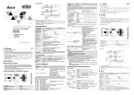
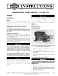
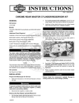
-J04324
REV. 2007-04-12
CHROME MASTER CYLINDER KIT
GENERAL
is05025
Kit Number
1
45355-08
Models
For model fitment information, please see the P&A Retail Catalog or the Parts and Accessories section of www.harleydavidson.com (English only).
Additional Parts Required
erman
G
.
e
.
y
n
1. Bore stamp size location
The rider's safety depends upon the correct installation
of this kit. Use the appropriate service manual procedures.
If the procedure is not within your capabilities or you do
not have the correct tools, have a Harley-Davidson dealer
perform the installation. Improper installation of this kit
could result in death or serious injury. (00333a)
1.
Open bleeder nipple caps on front brake caliper. Install
end of a length of clear plastic tubing over caliper bleeder
valves, while placing free end in a suitable container. Open
bleeder valves about 1/2-turn. Pump brake hand lever to
drain brake fluid. Close bleeder valve.
o p. d e
Rosto
ck
Figure 1. Verify Correct Master Cylinder Bore Size
A Service Manual for your motorcycle is available from any
Harley-Davidson Dealer.
See Figure 6 and Table 1.
Avoid leakage. Be sure gaskets, banjo bolt(s), brake line
and master cylinder bore are clean and undamaged before
assembly. (00322a)
MASTER CYLINDER REMOVAL
2.
See Figure 1. Master cylinders designed for dual disc (two
caliper) operation have an 11/16 inch (17.5 mm) bore, while
those that are designed for single disc (one caliper) operation
have a 9/16 inch (14.3 mm) bore. The bore size is stamped
(1) on the master cylinder assembly inboard of the handlebar
clamp bracket.
w
w
NOTE
w.
Remove bolt and two metal/rubber gaskets to disconnect
fitting of hydraulic brake line from master cylinder. Discard
gaskets.
sh
Kit Contents
h d o nli
Do not use an 9/16 inch bore master cylinder assembly on dual
disc (two caliper) models or dual disc 11/16 inch bore master
cylinder assembly on single disc (one caliper) models. These
master cylinder assemblies are not interchangeable. Using the
wrong assembly can adversely affect braking efficiency or
result in brake failure which could result in death or serious
injury.
n
e
Do not remove or install the master cylinder assembly
without first positioning a 5/32-inch (4 mm) thick insert
between the brake lever and lever bracket. Removing or
installing the master cylinder assembly without the insert
in place may result in damage to the rubber boot and
plunger on the front stoplight switch. (00324a)
3.
See Figure 2. Place the cardboard insert between the
brake lever and lever bracket.
D.O.T. 4 brake fluid will damage painted and body panel
surfaces it comes in contact with. Always use caution and
protect surfaces from spills whenever brake work is performed. Failure to comply can result in cosmetic damage.
(00239b)
-J04324
1 of 5
MASTER CYLINDER INSTALLATION
is01010
1.
Align hole in brake hand lever with hole in master cylinder
bracket. From the top of the assembly, slide pivot pin
through bracket and hand lever.
Wear safety glasses or goggles when removing or
installing retaining rings. Retaining rings can slip from the
pliers and could be propelled with enough force to cause
serious eye injury. (00312a)
2.
Install retaining ring in pivot pin groove. Verify that retaining
ring is completely seated in groove.
3.
See Figure 3. Position the brake lever/master cylinder
assembly inboard of the switch housing (4) assembly
engaging the tab (1) on the lower switch housing in the
groove (3) at the top of the brake lever bracket (2).
Figure 2. 5/32 in. (4 mm) Cardboard Insert
erman
G
.
e
.
y
n
See Figure 6. Using T-27 TORX® drive head, remove the
two screws with flat washers securing the handlebar clamp
to the master cylinder housing. Remove the brake
lever/master cylinder assembly and clamp from the handlebar.
1
5.
Remove retaining ring from pivot pin groove at bottom of
master cylinder bracket.
6.
Remove pivot pin and brake hand lever from master
cylinder assembly.
4
1.
2.
3.
4.
w
w.
h d o nli
4.
NOTE
New master cylinder comes with all internal components preassembled. It is not necessary to remove the components from
the bore of the old master cylinder. See Service Parts page.
Clean all previously used parts with denatured alcohol or
D.O.T. 4 BRAKE FLUID. Do not contaminate with mineral
oil or other solvents. Wipe dry with a clean, lint free cloth.
Use denatured alcohol to clean brake system components.
Do not use mineral-based solvents (such as gasoline or
paint thinner), which will deteriorate rubber parts even
after assembly. Deterioration of these components can
cause brake failure, which could result in death or serious
injury. (00291a)
8.
Carefully inspect all parts for wear or damage and replace
as necessary.
-J04324
Tab
Brake lever bracket
Groove
Switch housing
Figure 3. Brake Lever Bracket to Switch Housing
Do NOT allow dirt or debris to enter the master cylinder
reservoir. Dirt or debris in the reservoir can cause improper
operation and equipment damage. (00205b)
7.
3
o p. d e
Wear safety glasses or goggles when removing or
installing retaining rings. Retaining rings can slip from the
pliers and could be propelled with enough force to cause
serious eye injury. (00312a)
w
2
sh
Rosto
ck
4.
is01265
n
e
Align the holes in the handlebar clamp with those in the
master cylinder housing and start the two screws (with flat
washers). Position for rider comfort. Beginning with the
top screw, tighten the screws to 70-80 in-lbs (7.9- 9.0 Nm)
using a T-27 TORX drive head.
Avoid leakage. Be sure gaskets, banjo bolt(s), brake line
and master cylinder bore are clean and undamaged before
assembly. (00322a)
5.
Position new metal/rubber gaskets (included in kit) on
each side of hydraulic brake line fitting. Insert bolt through
gaskets and fitting. Thread bolt into master cylinder
housing and tighten to 17-22 ft-lbs (25-30 Nm).
6.
Install length of clear plastic tubing over caliper bleeder
valve, if removed. Place free end of tube in a clean container.
7.
Remove the master cylinder cover. Stand the motorcycle
upright so that the master cylinder is in a level position.
2 of 5
Direct contact of D.O.T. 4 brake fluid with eyes can cause
irritation. Avoid eye contact. In case of eye contact flush
with large amounts of water and get medical attention.
Swallowing large amounts of D.O.T. 4 brake fluid can cause
digestive discomfort. If swallowed, obtain medical attention. Use in well ventilated area. KEEP OUT OF REACH OF
CHILDREN. (00240a)
After repairing the brake system, test brakes at low speed.
If brakes are not operating properly, testing at high speeds
can cause loss of control, which could result in death or
serious injury. (00289a)
NOTE
The cover is labeled for D.O.T. 4 BRAKE FLUID. Install this
cover on reservoirs filled only with D.O.T. 4 BRAKE FLUID.
Do not mix grades of brake fluid as they are not compatible
and could cause equipment damage.
NOTE
NOTE
Never mix D.O.T 4 with other brake fluids (such as D.O.T. 5).
Mixing different types of fluid may adversely affect braking
ability and lead to brake failure which could result in death or
serious injury.
The sight glass enables the rider to visually check the brake
fluid level without removing the master cylinder cover. When
the reservoir is full, the sight glass is dark. As the fluid level
drops, the glass lightens up to indicate this condition to the
rider.
CLUTCH LEVER BRACKET REMOVAL
1.
See Figure 4. Loosen clutch adjuster so clutch cable is
fully slack by performing the following:
a.
Slide rubber boot (1) off cable adjuster.
b.
Holding cable adjuster (2) with 1/2 inch wrench,
loosen jam nut (3) using a 9/16 inch wrench.
c.
Back jam nut (3) away and turn cable adjuster (2)
toward jam nut to introduce a large amount of free
play at the clutch hand lever.
is01266
Verify proper operation of the master cylinder relief port.
Actuate the brake hand lever. A slight spurt of fluid will
brake the fluid surface in the reservoir compartment if all
internal components are working properly.
10. Add brake fluid to the master cylinder reservoir until the
fluid level is 1/8 inch (3.2 mm) from the top.
sh
1
w
12. Open bleeder valve about 1/2-turn. Brake fluid will flow
from bleeder valve through tubing. Close bleeder valve
when brake hand lever has moved 1/2 to 3/4 of its full
range of travel. Allow brake hand lever to return slowly to
its released position.
w.
h d o nli
1.
2.
3.
4.
15. Add brake fluid to the master cylinder reservoir until the
fluid level is about 1/8 inch (3.2 mm) from the top.
16. Note that the angular shape of the master cylinder cover
makes one side thicker than the other. Install the cover
(with gasket) on the master cylinder reservoir so that the
thicker side is positioned above the brake line fitting. Install
two Phillips screws to fasten the cover to the reservoir.
Tighten the screws to 6-8 in-lbs (0.7-0.9 Nm).
17. With the Ignition/Light Key Switch turned to IGNITION,
actuate the front brake hand lever to verify operation of
the brake lamp.
-J04324
n
e
4
Rubber boot
Cable adjuster
Jam nut
Cable end
Figure 4. Loosen Clutch Adjuster
13. Repeat Steps 10 through 12 until all air bubbles are
purged.
14. Final tighten the bleeder valve to 80-100 in-lbs (9.0-11.3
Nm). Install the bleeder cap.
3
2
11. Depress and hold the brake hand lever to build up
hydraulic pressure.
w
o p. d e
Be sure the master cylinder relief port is not plugged. A
plugged relief port can cause brake drag or lockup and
loss of vehicle control, which could result in death or
serious injury. (00317a)
9.
Stand motorcycle upright and level.
erman
G
.
e
.
y
n
2.
Add D.O.T. 4 SILICONE HYDRAULIC BRAKE FLUID to
the master cylinder reservoir until the fluid level is 1/8 inch
(3.2 mm) from the top. Do not reuse old brake fluid. Use
only D.O.T. 4 fluid from a sealed container.
Rosto
ck
8.
18. Test ride the motorcycle. If the brake feels spongy, repeat
the bleeding procedure.
3.
See Figure 6. Remove the clutch cable anchor pin (D)
from the hand lever (H). To remove anchor pin, it will be
necessary to remove the retaining ring (C) and pivot pin
(A).
4.
Remove clevis (E) and clutch lever.
5.
Using a T-27 TORX drive head, remove the two screws
with flat washers securing the handlebar clamp to the
clutch lever bracket.
CLUTCH LEVER BRACKET INSTALLATION
1.
See Figure 6. Install the clutch cable (F) and anchor pin
(D) in the clutch hand lever (H). The flat in the pin must
face in towards the hand lever.
3 of 5
2.
Put cable clevis in position in clutch lever and slide anchor
pin into place.
3.
Place clutch lever in new bracket and install pivot pin and
retaining ring.
4.
5.
Align the holes in the handlebar clamp with those in the
clutch lever bracket and start the two screws (with flat
washers). Position for rider comfort. Beginning with the
top screw, tighten the screws to 70-80 in-lbs (7.9-9.0 Nm).
NOTE
If clutch adjustment is necessary, refer to the applicable Service
Manual.
6.
Check clutch lever for proper operation.
is01012
4
2
Adjust clutch lever free play by performing the following:
a.
See Figure 4. Turn cable adjuster (2) away from jam
nut (3) until slack is eliminated at hand lever
b.
See Figure 5. Pull clutch cable ferrule (2) away from
clutch lever bracket (3) to check free play. Turn cable
adjuster as necessary to obtain 1/16-1/8 inch (1.6-3.2
mm) free play between end of cable ferrule and clutch
lever bracket.
c.
Hold adjuster with 1/2 inch wrench. Using 9/16 inch
wrench, tighten jam nut against cable adjuster.
d.
Cover cable adjuster with rubber boot.
1
1.
2.
3.
4.
3
Clutch cable
Cable ferrule
Clutch lever bracket
Freeplay 1/16-1/8 in. (1.6-3.2 mm)
erman
G
.
e
.
y
n
w
w
-J04324
o p. d e
sh
Rosto
ck
Figure 5. Clutch Hand Lever
w.
h d o nli
n
e
4 of 5
SERVICE PARTS
is05024
2
1
A
3
B
7
G
6
7
5
A
C
B
4
r
e
m
G
a
ny
e.
.
nF
Rosto
ck
5
6
H
E
o p. d e
C
D
Figure 6. Service Parts: Chrome Master Cylinder Kit
Item
Description (Quantity)
Part Number
Item
1
Cover assembly, chrome, DOT4
2
Screw, stainless steel (2)
3
Master cylinder assembly, brake, chrome, 45297-08
9/16 inch bore
B
4
Bracket, clutch lever, chrome
38403-99
C
Retaining ring
5
Clamp, handlebar, chrome (2)
45282-99A
D
Anchor pin
6
Washer, zinc (4)
6099
E
Clevis end
7
Screw, zinc (4)
4293
8
Gasket, brakeline 7/16 inch (2) (not shown) 41733-88
w
w
-J04324
Not Sold Separately
sh
Table 1. Service Parts: Chrome Master Cylinder Kit
w.
2573
Items mentioned in text but not in kit
A
h d o nli
e
Pivot pin
n
Bushing
F
Clutch cable
G
Brake hand lever
H
Clutch hand lever
5 of 5