1
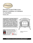
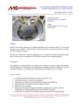
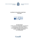
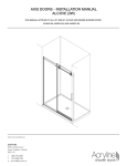
MARINE INVESTIGATION REPORT
M11L0160
GROUNDING
BULK CARRIER ORSULA
BATTURES DE GENTILLY, BÉCANCOUR, QUEBEC
15 DECEMBER 2011
The Transportation Safety Board of Canada (TSB) investigated this occurrence for the purpose
of advancing transportation safety. It is not the function of the Board to assign fault or
determine civil or criminal liability.
Marine Investigation Report
Grounding
Bulk Carrier Orsula
Battures de Gentilly, Bécancour, Quebec
15 December 2011
Report Number M11L0160
Summary
On 15 December 2011, at 0910 Eastern Standard Time, the bulk carrier Orsula departed
Contrecœur, Quebec, in ballast for Baie-Comeau, Quebec. While proceeding downbound on the
St. Lawrence River under the conduct of a pilot, the vessel lost steering control and ran aground
at 1329 on the Battures de Gentilly, 1.25 miles northeast of Bécancour wharf, Quebec. About
48 hours later, it was refloated on the first attempt using tugs. The vessel sustained hull
damage, which required repairs. There were no injuries or pollution as a result of this
occurrence.
Ce rapport est également disponible en français.
-2-
Factual Information
Particulars of the Vessel
Name of vessel
Orsula
IMO number
9110901
Port of registry
Majuro
Flag
Marshall Islands
Type
Bulk carrier
Gross tonnage
20 837
Length 1
200 m
Draught
Forward: 4.18 m
Aft: 6.8 m
Built
1996, Yiangnan Shipyard, Shanghai, China
Propulsion
B&W 6S50MC, 2-stroke, single-acting engine,
developing 8562 kW at 127 rpm
Cargo
Ballast, 9362 metric tons
Crew
20
Registered owner
Atlant Bulkers Corp., Majuro, Marshall Islands
Manager
Atlantska Plovidba d.d., Dubrovnik, Croatia
Description of the Vessel
The Orsula is a bulk carrier cargo vessel built of
steel, with machinery spaces and
accommodations located aft. The 6 cargo holds
and hatches are serviced by three 30-tonne
electrical-hydraulic cranes mounted on the
centreline of the vessel. The bridge is equipped
with all the required navigational equipment,
including both 3-cm and 10-cm radars distributed
on either side of the centreline (Figure 1). The
steering stand is situated off to the starboard side
of the centreline of the bridge, and an indication
is in place at the starboard window to enable
1
Photo 1. Orsula
Units of measurement in this report conform to International Maritime Organization (IMO)
standards or, where there is no such standard, are expressed in the International System (SI) of
units.
-3-
visual alignment with the steering light. The engine controls and the communication system are
located on the starboard console.
Figure 1. Bridge layout (diagram not to scale)
History of the Voyage
On 15 December 2011, the Orsula departed Contrecœur, Quebec, for Baie-Comeau, Quebec, in
ballast condition. At 1230, 2 the vessel arrived at the Pointe-des-Ormes pilot station. The pilot
assigned from Trois-Rivières, Quebec, to Québec, Quebec, boarded the vessel, along with an
apprentice pilot, to relieve the pilot assigned from Contrecœur to Trois-Rivières. At this point, a
pilot-pilot exchange took place. During the exchange between the master and the new pilot, the
pilot told the master that he would begin the passage at slow speed to allow sufficient time for
2
All times are Eastern Standard Time (Coordinated Universal Time minus 5 hours) unless
otherwise noted.
-4-
another vessel to manoeuvre in the port of Trois-Rivières. The pilot also informed the master of
his intention to keep the engine in the manoeuvring speed mode of 12 knots through the water 3
throughout the passage to Québec. The engine control was set to bridge control. The bridge
team was comprised at this time of the master, the second officer acting as officer of the watch
(OOW), a pilot, an apprentice pilot, and a helmsman.
The helmsman responded well to the helm orders using the helm wheel in full follow-up (FFU)
mode, and that he steered the vessel steadily. At this time, the pilot connected his portable pilot
unit (PPU) and used his own global positioning system (GPS) antenna to feed the PPU. The
pilot then allowed the apprentice pilot to conduct the vessel, while still supervising him. At
around 1315, the vessel approached Course de Bécancour, and the apprentice altered course to
050° gyro (G) 4 to steer on the next set of ranges. At around this time, the master left the bridge.
At 1324, the vessel passed 0.4 nautical miles (nm) abeam Bécancour wharf while still in line with
the ranges. At around 1326, the vessel was near buoy C21 and had reached the point at which
the pilot was to initiate a turn to port. The apprentice ordered the helmsman to bring the vessel
to a heading of 045°, and the helmsman confirmed this order by repeating the heading.
However, the rudder angle indicator showed 10º to starboard. The apprentice then ordered the
heading 045º again, and the helmsman confirmed by repeating it. With the rudder angle
indicator still showing 10º to starboard, the apprentice ordered the helmsman to put the helm at
midship, 5 but there was still no rudder movement showing on the rudder angle indicator.
The apprentice then advised the pilot of the situation. The pilot took over the conduct of the
vessel and ordered 20° of port rudder. The rudder angle indicator remained at 10º to starboard.
The pilot then ordered hard to port but, upon seeing no result, ordered 10º of starboard rudder.
No rudder movement could be observed on the rudder angle indicator. The pilot then ordered
the engine to be stopped, that somebody be ready to drop the anchor, and that emergency
steering be activated. At this time, the vessel was more or less steady on a course of
approximately 050°.
The OOW called the master and moved the engine telegraph handle from full ahead to stop, at
which time the vessel’s speed was approximately 15 knots speed over ground (SOG). The OOW
then went and stood by the steering stand. At the same time, the pilot called Marine
Communication and Traffic Services (MCTS), informing them that the vessel was out of control
and would soon exit the channel. At about 0.5 nm east of buoy C21, the vessel started exiting
the channel with a slow turn to starboard. The pilot ordered the main engine full astern, and the
OOW set the engine telegraph to full astern. 6
3
Speed through the water is a measure of speed that does not take into account current or wind.
On the other hand, speed over ground (SOG) accounts for the current and wind speed.
4
All courses are gyro compass headings unless otherwise specified.
5
Midship is when the rudder angle is at 0°.
6
To be able to reverse the engine and apply full astern thrust, the main engine revolutions per
minute need to reach a low enough level to apply braking air in order to expedite the slowing
and reversing of the engine. By the time the main engine was reversed and full astern was
available, the vessel had already grounded.
-5-
At 1327, the pilot reported to MCTS that the vessel was leaving the channel and would soon
ground. At approximately 1328, the master came on the bridge. He went directly to the steering
stand and transferred the steering system actuator switch from port to starboard, restoring
control to the steering. Nonetheless, at 1329, as the bosun and OOW were out on deck on their
way to attend the anchors, the vessel ran aground at an estimated speed of 8 knots SOG. At
1331, the pilot called MCTS to report that the vessel was aground in position 46°25.4′ N and
072°21.6′ W with a heading of 079°.
Post-Occurrence Examination of Steering Stand
Following the grounding, when the vessel was towed to the Port of Bécancour, a call was made
to an authorized representative of Sperry Marine to examine the bridge steering stand
components. The examination determined that the port steering system helm potentiometer had
failed. As part of the service call, the 3 potentiometers in the steering stand were replaced, and
the system was found to be functional.
Vessel Certification
The Orsula carried all appropriate certificates for a vessel of its class and for the voyage. A
Safety Management Certificate (SMC) had been issued to the vessel by Det Norske Veritas
(DNV) in Norway on 13 November 2008 and was valid until 27 September 2013. This certificate
was endorsed after an intermediate verification 7 on 06 August 2011. The vessel was thus in
compliance with the requirements of the International Safety Management (ISM) Code. 8
Crew Certification and Experience
The crew of the Orsula were all properly certified for their positions on board. The master held a
Master Mariner certificate of competency endorsed by the Marshall Islands Maritime
Administrator and had sailed as a master on various vessels belonging to the same company
since 2004. He joined the Orsula in September 2011, having served on board as master several
times since 2005.
The OOW held an Officer of the Watch certificate of competency, issued in April 2011 and
endorsed by the Marshall Islands Maritime Administrator, and had been sailing on different
vessels in that position since July 2011. He joined the Orsula on 12 December 2011.
The helmsman had been sailing since 1981 and obtained his Bridge Watchman certificate in
1987 in Croatia. He had been with this company since 2006 and joined the Orsula in October
2011.
7
The SMC was subject to at least 1 intermediate verification to be carried out between the second
and third anniversary dates of the SMC, in accordance with regulation IX/6.1 of the International
Convention for the Safety of Life at Sea (SOLAS) and paragraph 13.8 of the ISM Code.
8
International Management Code for the Safe Operation of Ships and for Pollution Prevention
-6-
The pilot held a Master Inland Waters certificate and obtained his District 1, Class B2 pilot
licence in April 2011. The apprentice pilot held a Master Near Coastal certificate and obtained
his District 1, Class D apprentice licence in April 2011.
Environmental Information
On 15 December 2011, in the region of Trois-Rivières–Bécancour, the visibility was about
2 miles, and the sky was overcast with light rain. High tide was at 1351 in Trois-Rivières and at
1330 in Bécancour. The water level in Bécancour was predicted to be 1.2 m above chart datum at
high tide.
Damage to the Vessel
On 17 December 2011, an underwater survey of the Orsula was conducted at the Port of
Bécancour. The survey revealed the following:
•
2 cracks, one 1500 mm x 50 mm and the other 500 mm x 40 mm, in way of the bow
thruster;
•
long indents (8 m x 70 mm deep) found on the port and starboard bow;
•
starboard bulkheads between the bow thruster room and forepeak tank were found
buckled and detached at the bottom;
•
numerous transverse floors were found buckled and detached at the bottom over a
length of 1 m.
Steering Gear
The Orsula is equipped with an electro-hydraulic Rapson Slide (type FM21-072) steering gear
with 2 rams and 4 cylinders, manufactured by Kawasaki-Wuhan. The hydraulic cylinders are
supplied by 2 variable-delivery main steering gear pumps operated through a floating lever
arrangement driven by a set of 2 telemotor receivers. Only 1 telemotor receiver can be used at a
time, but it can drive either 1 or 2 variable-delivery main steering pumps at the same time.
In case of failure of all remote steering gear control systems, it is possible, as an emergency
measure, to detach the 2 telemotor receivers from the floating lever arrangement and connect a
hand trick wheel 9 to directly and manually operate the variable-delivery main steering pump.
However, in order to do this, an operator must be situated locally in the steering gear
compartment to operate the trick wheel and follow orders given by bridge personnel through a
communication device.
9
A wheel located in the steering gear compartment which, in an emergency, manually drives the
telemotors operating the rudder
-7-
Bridge Helm Unit
The Orsula is fitted with a Sperry Marine steering control system (model ADG-3000). This
system, fitted during the construction of the vessel and approved by the classification society,
includes an all-electric helm unit that incorporates hand-steering capabilities and autopilot
functions.
A steering control mode selector switch,
located on the upper left-hand side of the
steering stand, is used to select 1 of
3 different means of steering the vessel:
autopilot, hand or non-follow-up (NFU).
When the steering mode selector switch is
set to the “hand” position, the helm wheel
is activated, permitting the helmsman to
operate the steering in FFU mode. In FFU
mode, when the operator changes the
position of the helm wheel, the rudder
begins to move and keeps moving until it
reaches the ordered position indicated on
the helm. To return the rudder to the
neutral (0°) position, the helm wheel must
be manually positioned to 0°. The helm
order data signal to the steering gear
telemotors is provided by
2 potentiometers that are mechanically
linked to the helm wheel and electrically
linked to each telemotor: 1 potentiometer
per telemotor.
Typically, when the NFU mode is
selected, the NFU controller becomes
operational and the helm wheel is
deactivated. However, on the Orsula, once
the NFU controller is used, it overrides all
Figure 2. Bridge helm unit arrangement
other steering controllers without the need
to set the steering mode selector switch to NFU. The NFU controller is a spring-loaded lever
that must be held to one side or the other for a signal to be sent to the steering gear telemotors.
Operating the NFU control causes the rudder to rotate left or right for as long as the control is
held in the left or right position. On releasing the control, the rudder stops rotating and holds its
position until the NFU controller is again operated.
A steering system selector switch is located on the upper right-hand side of the steering helm
unit. The steering selector switch selects either the port or starboard steering system. Each of
these systems controls the steering gear telemotor.
-8-
Replacement of Steering Stand Components
The steering stand on the Orsula was manufactured by Sperry Marine. At the time of the
occurrence, the steering stand instruction booklet on board the vessel, the “Sperry Helm
Steering Assembly Operation and Service Manual,” made no reference to the need to replace
potentiometers. The manual advised the crew to perform monthly tests of the steering to verify
the functioning of the potentiometer by positioning the steering wheel to one-third of a full
turn, two-thirds of a full turn, and then a full turn on both sides—each time ensuring that the
rudder indicator matches the wheel order.
By comparison, another manufacturer, Litton Marine, issued in 1999 the “Steering Gear Tests,
Drills and Preventative Maintenance” notice for the C.Plath steering stand type, in which it
recommended the replacement of potentiometers in steering stands at minimum intervals of
5 years.
Inspection of Steering Stand
On 10 December 2011, an authorized representative of Sperry-Alliance Nav visited the Orsula in
the Port of Contrecœur at the request of the master. While the work order was to inspect the
gyro, the master also requested that the technician perform a general test of the steering console.
During this general test, the technician did not specifically inspect the potentiometers. The
technician was aware of the recommendation from the other manufacturer to replace the
potentiometer after a period of time, but found no defects on the steering console.
The potentiometer that failed on board the Orsula was manufactured in 1994. The potentiometer
did not have any physical label to identify the manufacturing date. Instead, it was marked with
a serial number that an individual could use as a reference when calling the manufacturer to
determine the manufacturing date.
Laboratory Analysis
Upon examination of the potentiometer, visible contamination was found on the lower bearing,
resembling a powder of a brown hue. The balls and races had been affected by some
deterioration, likely due to the abrasive action of that contamination. The deterioration of the
surfaces likely resulted in the need for additional force to rotate the shaft of the potentiometer,
which in turn deformed and cracked the bearing cage. The examination concluded that the
potentiometer did not turn freely due to the failure of its lower bearing, which had seized due
to the deformation and cracking of its cage. 10
The investigation was not able to determine the origin of the contamination.
Review of Alternative Steering Methods
The TSB conducted a review of 8 vessels from different owners and flag states in the Port of
Québec to determine the general knowledge and use of the NFU mode by bridge crew
members. This revealed that, on 6 out of the 8 vessels reviewed, the crew members were not
10
TSB Laboratory report LP 180/2011, available upon request
-9-
fully familiar with the use of the NFU mode. In general, it was found that, when they first
boarded the vessel, helmsmen were only given brief explanations of the different steering stand
components and their use, including the NFU mode. Furthermore, the procedures for dealing
with situations involving steering failures refer primarily to the local emergency steering in the
steering gear compartment. Use of the NFU mode, if it is referred to, is usually listed as a
secondary or tertiary method to regain control.
On the Orsula, 1 steering system is used to control the steering when in hand-steering mode. In
the event of a steering failure, switching to another steering system can be a solution to regain
control. The deficient potentiometer was linked to the port telemotor. When the master came
back on the bridge, he switched the steering system selector switch from port to starboard,
which restored steering control.
Reversing the Main Engine
The vessel is fitted with a direct-drive reversible low-speed engine. The engine drives 1 fixedpitch propeller, and the vessel service speed is approximately 15 knots.
The bridge control of the engine enables a crew member to start the engine ahead or astern and
choose different speed settings. To switch from ahead to astern movement, the engine must be
allowed to slow down to a designated revolution (37 rpm) to prevent excessive stresses and
forces before it can then be set into reverse mode and restarted astern.
When the main engine is set to full ahead (127 rpm) and the vessel speed is 14.8 knots, it takes
155 seconds for the engine to set into astern starting mode. As well, in the case of an emergency
stop (putting the telegraph from full ahead to full astern), the vessel can be stopped in 5 minutes
and 21 seconds. 11 This information was posted on a bulkhead in the wheelhouse.
Crew Familiarization Checklist
The managing company established different checklists to account for different aspects of safety
maintenance, verification and training for the crew. Among these, form NAV09, entitled
“Familiarization with Bridge Equipment,” lists navigation equipment and controls to be studied
and understood by the bridge crew member. When all of the items are checked off to indicate
completion of familiarization, the form is signed by the crew member and the master. On the
Orsula, this form was found to be completed and signed.
Also, form NAV10, entitled “Bridge Preparation for Departure,” lists a series of verifications of
bridge equipment to be completed prior to departure (Appendix C). Among these, the steering
gear is to be verified in several ways.
Neither NAV09 nor NAV10 contained any information regarding the operation of the NFU
mode or the option to switch from the port to the starboard steering system for steering control.
11
Data based on information collected during sea trials of the Orsula prior to delivery to owner.
-10-
Drills
In Chapter V, Regulation 26 of the International Convention for the Safety of Life at Sea (SOLAS),
there is a description of the tests and drills that must be performed on a steering gear
(Appendix B). The series of verifications stated in SOLAS are the same as those in the safety
management system documentation on board the Orsula (Appendix C). Neither is specific
about the use of the NFU mode or switching from the port to the starboard steering system, or
how these technical means of steering can be used in cases where steering control is lost.
Voyage Data Recorder
In addition to bridge audio, a simplified voyage data recorder (S-VDR) is capable of recording
such items as time, vessel heading and speed, gyrocompass, alarms, very high frequency (VHF)
radiotelephone communications, radar, echo-sounder, wind speed and direction, and
rudder/engine orders and responses.
SOLAS requires that annual performance tests of the S-VDR be conducted by an approved
testing or servicing facility. 12 The last annual performance test certificate on board the Orsula
was dated 02 May 2011.
The Orsula had a valid safety management certificate, as required by the ISM Code; therefore,
there was a safety management system on board the vessel. The safety management system
included a pre-departure checklist, NAV10, which required verification of the readiness of the
S-VDR. The pre-departure checklist indicated that the S-VDR had been verified by the bridge
crew before leaving Contrecœur.
On the Orsula, the S-VDR was not recording at the time of the occurrence and had not recorded
any data since May 2011. The S-VDR started recording 3 hours after the vessel went aground on
15 December 2011. 13
12
Regulation V/18(8)
13
TSB Laboratory Report LP182/2011, available upon request
-11-
Analysis
Events Leading to the Grounding
When the helm follow-up potentiometer of the port steering system failed, the electrical link
between the steering stand and the telemotor in the steering gear compartment ceased to
function, and control of rudder movement was lost. At this time, the rudder angle indicator was
showing 10º to starboard. The vessel veered to starboard when it was intended to alter course to
port.
When the vessel’s crew members on the bridge became aware that the rudder was not
responding, 3 options were available on the bridge to rectify the situation: taking over the
steering control with the non-follow-up (NFU) mode, changing over from the port to the
starboard steering system to also regain steering control, or stopping the vessel. However,
stopping the vessel was not a viable option because of the vessel’s proximity to the shore and
the length of time required to put the engine at full astern and stop the vessel. Thus, while in
this case the engine was ordered full astern, the engine went astern only after the vessel had
grounded.
The other 2 options in this situation involved regaining control of steering. There was no
attempt made by the officer of the watch (OOW) or the helmsman to use the NFU mode or to
switch from the port to the starboard steering system because they were not familiar with either
option. By the time the master returned to the bridge and switched the steering system selector
switch from port to starboard, restoring control of rudder movement, it was too late to prevent
the grounding.
Potentiometer Failure
Potentiometers send signals to a steering system amplifier and corresponding telemotors, and
are mechanically connected to the helm wheel with gearwheels. As critical components of the
steering gear control, potentiometers require adequate testing and record keeping to ensure that
they continue to function effectively.
In this occurrence, the potentiometer connected to the port steering system failed, disrupting
the link between the steering stand and the port telemotor in the steering gear compartment,
resulting in the loss of control of rudder movement. The potentiometer had failed due to the
consequences of contamination; however, the investigation was not able to determine the origin
of this contamination.
The instruction manual for the Sperry Marine steering stand on board the Orsula, the “Sperry
Helm Steering Assembly Operation and Service Manual,” advised the crew to perform monthly
verifications of the steering that would test the potentiometer. This is done by positioning the
steering wheel to one-third of a full turn, two-thirds of a full turn, and then a full turn—each
time ensuring that the rudder indicator matches the wheel order. While the NAV10 checklist,
that contains the procedures that the crew of the Orsula performed before each departure, does
require a steering test, this steering test does not fully correspond to the procedure stated in the
manual. Referring to Appendix C, the checklist requires a steering gear test where the wheel is
-12-
turned hard over to port and hard over to starboard. Therefore, this procedure may not have
adequately served to test the potentiometer in accordance with the manufacturer’s instructions.
The regular testing of steering merely verifies that the potentiometer is functional at the specific
time of a given test. If one of the potentiometers fails, the bridge operator can either switch to
the alternate steering system or regain steering control using the NFU mode. The effectiveness
of these 2 options available to the bridge operator depends on the operator’s awareness of and
ability to use these options in the event of a failure.
The Sperry Marine instruction manual on board the Orsula did not contain any reference to the
need to replace potentiometers. The potentiometer that failed in this occurrence had been
manufactured in 1994. Other manufacturers, such as Litton Marine, recommend that
potentiometers in steering stands be replaced at minimum intervals of 5 years. Without regular
replacement of potentiometers, there is an increased risk that they will fail in service.
Familiarity with Steering Control Modes
To react effectively in emergency situations where there is a loss of steering control, a crew must
be aware of the means to regain that control. This is especially crucial when the vessel is sailing
in restricted waters. That awareness can come from technical manuals, familiarization, drills,
and posted procedures.
Steering control was lost on the Orsula when one of the potentiometers failed. Using the NFU
mode in situations such as these is an efficient and effective way to try to regain control of the
vessel’s steering. Also, another effective method is to switch from the port to the starboard
steering system. However, neither the helmsman nor the OOW tried the NFU mode or switched
the steering systems to regain control.
The helmsman and OOW were not familiar with these methods, and they did not make use of
them in this occurrence. Neither method was specifically addressed in Orsula’s on-board
familiarization, as they were not included in the NAV09 or NAV10 checklists. There was no
specific information on these methods posted near the steering stand or specified in the onboard “Sperry Helm Steering Assembly Operation and Service Manual.” The procedure for
emergency steering drills, in compliance with SOLAS, also did not include the testing and use
of the NFU mode or switching steering systems. As such, there were limited opportunities for
the bridge crew to become familiar with these 2 means of regaining steering control on board
the Orsula.
Furthermore, the TSB’s review of 8 vessels found that the lack of awareness of the NFU mode is
not limited to the Orsula and may be an indication of a broader problem. Therefore, if
information on steering control methods, such as the NFU mode or switching steering systems,
is not adequately incorporated into technical manuals, familiarization, and drills, or adequately
described and posted near steering stands, crew may be unfamiliar with these methods. As in
the Orsula, a lack of familiarity with either method can put the vessel and its crew at risk when a
means of regaining steering control is needed in an emergency.
-13-
Voyage Data Recorder
The purpose of a voyage data recorder (VDR) is to create and maintain a secure, retrievable
record of information indicating the position, movement, physical status, and control of a vessel
for the period covering the most recent 12 hours of operation. Objective data is invaluable to
investigators when seeking to understand a sequence of events and identify operational
problems and human factors.
The pre-departure checklist on board the Orsula (NAV10) indicated that the simplified voyage
data recorder (S-VDR) had been verified by the bridge crew prior to departure; the crew did not
see any indication that the S-VDR was malfunctioning. Furthermore, the investigation did not
determine why the VDR was not recording at the time of the occurrence, nor why it had not
recorded data since May 2011. The VDR started recording 3 hours after the vessel went aground
on 15 December 2011.
When VDR data, in particular bridge audio recordings, are not available to an investigation, this
may preclude the identification and communication of safety deficiencies to advance
transportation safety.
-14-
Conclusions
Findings as to Causes and Contributing Factors
1. Steering control was lost when the port steering system potentiometer failed while the
rudder angle was at 10º to starboard, causing the vessel to veer to starboard and leave
the dredged channel.
2. The bridge crew members were not familiar with the use of the non-follow-up mode or
with switching the steering system selector switch from port to starboard to regain
steering control.
3. The master switched the steering system selector switch from port to starboard, which
restored steering control, but it was too late to prevent the vessel from running aground.
Findings as to Risk
1. Without the regular replacement of potentiometers, there is an increased risk that they
will fail in service.
2. Crew may be unfamiliar with the steering control methods of the non-follow-up mode
or switching steering systems in cases of steering failure if this information is not
incorporated into technical manuals, familiarization, and drills, or adequately described
and posted near the steering stand.
3. When data from the voyage data recorder, in particular the bridge audio recordings, are
not available to an investigation, this may preclude the identification and
communication of safety deficiencies to advance transportation safety.
-15-
Safety Action
Action Taken
TSB
On 03 January 2012, the TSB issued a Marine Safety Advisory Letter (MSA) 07/11 to the
International Association of Classification Societies (IACS), a copy of which was also sent to
Transport Canada, Fednav Limited (as sister vessel owners), Anglo-Eastern Ship Management
(as sister vessel manager), Sperry Marine, and Det Norske Veritas (DNV), Republic of the
Marshall Islands, for it to consider informing its member classification societies of the
circumstances of this steering gear failure and of the necessity to replace potentiometers in
similar Litton Marine System (Sperry Marine) steering systems at or before the recommended
interval of 5 years. The letter also requested that IACS consider verifying that the
manufacturer’s service instructions are on board vessels fitted with similar systems.
Owner
After this occurrence, the owner instructed all vessels in its fleet to perform an "Emergency
Steering Drill" on Sundays. During the drill, the master is to explain to all deck officers and
helmsmen how to change from the follow-up to the non-follow-up steering mode. After this
explanation, the crew must demonstrate these techniques to the master.
The owner also included emergency changeover arrangements for steering gear in the
"Familiarization with Bridge Equipment" and "Bridge Preparation for Arrival/Departure"
checklists. The understanding of these checklists should be demonstrated by all navigating
officers and helmsmen during each emergency drill.
Furthermore, the owner revised the safety management system for the Orsula and other vessels
with the same equipment to include the requirement to replace potentiometers every 5 years for
preventative maintenance.
Sister Vessel Owner
On 07 February 2012, the FedNav Owned Fleet department forwarded a copy of the MSA to its
technical managers, requesting that they follow up with the FedNav vessels under their
management.
Lloyd’s Register
On 22 February 2012, Lloyd’s Register issued Classification News No. 07/2012 to all vessel
owners and operators, strongly recommending that they ensure that all service bulletins are
maintained up-to-date with a copy retained on board, and that necessary maintenance
procedures are adhered to on steering control potentiometers.
-16-
China Classification Society
On 17 April 2012, the China Classification Society (CCS) issued Classification Information notice
No. 196 to distribute the MSA to relevant shipping companies. The information has also been
published on the CCS website.
International Association of Classification Societies Limited
On 06 June 2012, IACS responded to the TSB stating that it had distributed the MSA to its
members and that it would officially reply to the MSA once it had received feedback.
On 02 July 2012, IACS responded to the TSB stating that it had informed individual member
classifications societies of the circumstances of the steering failure. IACS considers that it is the
responsibility of the manufacturer of the steering system or potentiometer to identify the vessels
fitted with this equipment and to inform the concerned owners/operators of all updated
instructions and recommendations for the equipment.
Marshall Islands Maritime Administrator
The Marshall Islands Maritime Administrator recommends that the operator of the Orsula
reviews, and revises as appropriate, its procedures and checklists for documenting the
familiarization of on-signing officers of the watch with the vessel’s bridge equipment. It also
recommends that the officer be required to demonstrate to the master and/or chief officer their
ability to operate the steering gear in all modes of operation. In addition, it is recommended that
these procedures include ensuring that the on-signing officer is familiar with how to respond to
a steering failure when navigating in restricted waters without intervention from the master.
Also, it is recommended that these familiarization requirements be included as a pre-requisite
for crew members serving as helmsmen.
Furthermore, the Maritime Administrator recommends that the operator ensure that all officers
of the watch and helmsmen currently serving on vessels in its managed fleet receive hands-on
training, that they are able to demonstrate proper operation of the steering gear in all modes of
operation, and that they are familiar with the proper response to a steering failure in restricted
waters.
It is also recommended that the operator use the lessons learned from this occurrence as a case
study for enhanced bridge team management training for its crews.
Safety Concerns
Familiarity with Steering Control Modes
Steering is a critical aspect of operating a vessel. Vessels that are compliant with the International
Convention for the Safety of Life at Sea (SOLAS) are required to have at least 2 independent
steering control systems, designed so that there is a built-in redundancy. In this occurrence,
when the rudder did not respond, the on-watch personnel did not know why and did not select
the alternate steering system. A quick response would have allowed the vessel to regain
steering control before it departed the channel and grounded. As such, familiarity with and use
-17-
of these steering systems is of the utmost importance in situations where a steering system fails
and there is limited time available to regain steering control.
SOLAS Chapter V, Regulation 26 states the following: “all ships’ officers concerned with the
operation and/or maintenance of steering gear shall be familiar with the operation of the
steering systems fitted on the ship and with the procedures for changing from one system to
another.” The information can be conveyed through technical manuals, familiarization, drills,
and posted procedures.
When the potentiometer failed on the port steering system of the Orsula, the use of the
alternative remote steering systems on the bridge was the fastest method of regaining steering
control. On the Orsula, the steering systems available on the bridge were as follows:
•
•
•
Remote full follow-up (FFU) mode using the helm wheel on the port steering system.
Remote FFU mode using the helm wheel on the starboard steering system.
Remote non-follow-up (NFU) mode using the hand lever.
However, the on-watch personnel were not familiar with the use of these systems and, as such,
did not make use of them during this occurrence.
During the investigation, the TSB visited 8 vessels to verify the crew’s familiarity with steering
systems. The TSB found that the lack of awareness of alternative steering systems was not
limited to the Orsula, which indicates a broader problem.
In the past 10 years, the TSB has recorded approximately 180 occurrences related to steering
failure. While most of these did not result in groundings, steering failures nonetheless present
significant risks to a vessel’s operation. In one of these occurrences, involving the vessel Fossnes
(occurrence number M00L0114), similar safety concerns as that of the occurrence involving the
Orsula were identified.
Furthermore, the Australian Transport Safety Bureau (ATSB), in its report on the 31 July 2008
grounding of the bulk carrier Iron King at Port Hedland, Western Australia, identified, as a
safety issue, a lack of drills and training on the procedures to be used when steering is lost. In
the Iron King incident, the vessel’s SMS procedures stated that emergency steering drills should
be carried out, but did not explain how to do so.
In light of the potential hazards associated with the loss of steering control on vessels, the Board
is concerned that shortcomings in the familiarization and training of crew members with
regards to steering systems may result in risks to life, property, and the environment. The Board
will be monitoring the situation to determine if appropriate remedial action is being taken and
will assess the need for further action on this issue.
Availability of Voyage Data Recorder Data
The purpose of a voyage data recorder (VDR) is to create and maintain a secure, retrievable
record of information related to the position, movement, physical status, command and control
of a vessel. Objective data—voice data in particular—are invaluable to investigators seeking to
-18-
understand the sequence of events leading up to an occurrence. In this investigation, voice data
recorded by VDR would have been a highly effective means of gathering information about the
activities of the bridge team.
Upon reviewing past occurrences investigated by the TSB, it was determined that the failure of
VDRs to function as intended is not uncommon. For example, on 31 March 2011, the VDR on
the BBC Steinhoeft 14 was found to have ceased functioning prior to the grounding, thus making
important information inaccessible to the TSB. Likewise, in other occurrence investigations
(M10H0006/Clipper Adventurer, M09C0051/Federal Agno, and M05L0205/Cast Prosperity and
tanker Hyde Park), the VDR data was unavailable for different reasons, which impeded the work
of the TSB. In addition, numerous marine occurrence investigations worldwide have identified
a similar problem regarding malfunctioning or non-operating vessel VDRs.
Given this history and the occurrence of the Orsula, the Board is concerned that when VDR
data, in particular bridge audio recordings, are not available to an investigation, this may
preclude the identification and communication of safety deficiencies to advance transportation
safety. The Board will be monitoring the situation with a view to assessing the need for further
safety action on this issue.
This report concludes the Transportation Safety Board’s investigation into this occurrence. Consequently,
the Board authorized the release of this report on 23 January 2013. It was officially released on
07 February 2013.
Visit the Transportation Safety Board’s website (www.bst-tsb.gc.ca) for information about the
Transportation Safety Board and its products and services. You will also find the Watchlist, which
identifies the transportation safety issues that pose the greatest risk to Canadians. In each case, the TSB
has found that actions taken to date are inadequate, and that industry and regulators need to take
additional concrete measures to eliminate the risks.
14
TSB Occurrence M11C0001
-19-
Appendix A – Area of the Occurrence
-20-
Appendix B – SOLAS Chapter V
REGULATION 26 - Steering Gear: Testing and Drills
1. Within 12 hours before departure, the ship’s steering gear shall be checked and tested by
the ship’s crew. The test procedure shall include, where applicable, the operation of the
following:
.1 the main steering gear;
.2 the auxiliary steering gear;
.3 the remote steering gear control systems;
.4 the steering positions located on the navigation bridge;
.5 the emergency power supply;
.6 the rudder angle indicators in relation to the actual position of the rudder;
.7 the remote steering gear control system power failure alarms;
.8 the steering gear power unit failure alarms; and
.9 automatic isolating arrangements and other automatic equipment.
2. The checks and tests shall include:
.1 the full movement of the rudder according to the required capabilities of the
steering gear;
.2 a visual inspection for the steering gear and its connecting linkage; and
.3 the operation of the means of communication between the navigation bridge
and steering gear compartment.
3.1. Simple operating instructions with a block diagram showing the change-over
procedures for remote steering gear control systems and steering gear power units
shall be permanently displayed on the navigation bridge and in the steering
compartment.
3.2. All ships’ officers concerned with the operation and/or maintenance of steering gear
shall be familiar with the operation of the steering systems fitted on the ship and with
the procedures for changing from one system to another.
4. In addition to the routine checks and tests prescribed in paragraphs 1 and 2, emergency
steering drills shall take place at least once every three months in order to practice
emergency steering procedures. These drills shall include direct control within the
steering gear compartment, the communications procedure with the navigation bridge
and, where applicable the operation of alternative power supplies.
5. The Administration may waive the requirements to carry out the checks and tests
prescribed in paragraphs 1 and 2 for ships which regularly engage on voyages of short
duration. Such ships shall carry out these checks and tests at least once every week.
-216. The date upon which the checks and tests prescribed in paragraphs 1 and 2 are carried
out and the date and details of emergency steering drills carried out under paragraph 4,
shall be recorded.
-22-
Appendix C – Form Number NAV10