1
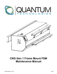
CNG Gen 1 Back Of Cab FSM
Installation Manual
Printed April 20, 2015
Rev A
CNG Gen 1 BOC FSM Installation Manual
Preface
This manual contains information and instructions required for the installation of the Quantum Fuel Systems
Technologies Worldwide, Inc. CNG fuel storage and compression system. A thorough and complete understanding
of the information and instructions contained in this manual is required for the installation and continued safe
operation of the system. Read this manual from cover to cover and keep it for future reference.
The system must only be installed and serviced by trained and certified technicians who have read and understood
this manual. Individual operator training is the responsibility of the company, firm, or organization placing the
system in service. Reading this manual does not constitute certification.
This manual contains Cautions and Notices that must be observed at all times to reduce the risk of personal injury
during operation or installation. Improper installation procedures may damage the system or make the system
unsafe to operate. These Cautions and Notices are not all inclusive. Quantum Fuel Systems Technologies
Worldwide, Inc. cannot possibly warn of all the potentially hazardous consequences caused by a failure to follow
these instructions.
If you need further information or have any questions, please contact:
Quantum Fuel Systems Technologies Worldwide, Inc.
25242 Arctic Ocean Drive
Lake Forest, CA 92630
USA
Tel: 949.930.3400
Fax: 949.930.3401
All information, illustrations, and specifications are based on the latest product information available at the time of printing.
Quantum Fuel Systems Technologies Worldwide, Inc. reserves the right to make changes at any time without notice.
This information is the intellectual property of Quantum Fuel Systems Technologies Worldwide, Inc. and may not be altered in
any way. This information is protected by the copyright laws of the United States of America, and other countries, and may not
be reproduced, stored in any retrieval system, or transmitted in any form or by any means (including but not limited to electronic,
mechanical, photocopying, and recording) without the prior written permission of Quantum Fuel Systems Technologies
Worldwide, Inc.
2015 Quantum Fuel Systems Technologies Worldwide, Inc.
i
CNG Gen 1 BOC FSM Installation Manual
How to Use This Manual
This supplement contains information specific to the Back Of Cab (BOC) CNG fuel storage module (FSM). It does
not explain everything you need to know about working with CNG equipment. You must use this installation manual
along with the service manual for the other installed components. Only then will you be able to properly install and
operate your equipment.
This manual contains information for the Gen 1 BOC CNG fuel storage module.
ii
CNG Gen 1 BOC FSM Installation Manual
Ordering Parts
To purchase repair or replacement parts for the Gen 1 CNG Fuel Storage Module (115696 / 116353 / 116785)
contact your local Quantum sales representative.
Technical Assistance
For questions regarding the installation, maintenance, and service for the Gen 1 CNG Fuel Storage Module contact
Quantum Technical Assistance at 800.816.8691.
Price List
Published prices are accurate at the time of print and are subject to change without notice. For part pricing, contact
your local Quantum sales representative.
iii
CNG Gen 1 BOC FSM Installation Manual
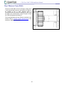
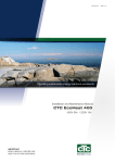
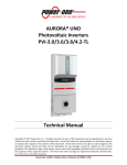
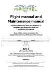
Module Identification
Generation 1
115696 – Fill Panel
116353 – Fill Panel
116785 – No Fill Panel (Slave)
All of the generation 1 BOC FSMs will have two
exposed lift hooks (1) located at the top front of the
module.
There are two additional lift hooks located under the
rear cover. The FSM has been designed with 4 lift
points to safely lift and maneuver the module for
service, maintenance, and / or inspection as needed.
1
Models with a fill panel (2) can be visually identified
with a configuration as shown in the illustration to the
right.
2
The slave model will not have any fill panel.
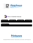
The part identification label (3) will be located in two
separate locations depending on whether the FSM is
equipped with a fill panel or if the FSM is a slave
module.
If the FSM is equipped with a fill panel, then the part
identification label is located on the inner left portion of
the fill panel assembly.
If the FSM is a slave module, then the part
identification label can be located inside the cylinder
access panel on the frame.
3
iv
CNG Gen 1 BOC FSM Installation Manual
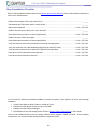
Table of Contents
Introduction ....................................................................................................................................................................1 Safety ..............................................................................................................................................................................2 Safety Features ..............................................................................................................................................................4 System Overview ...........................................................................................................................................................5 System Design and Operation ......................................................................................................................................5 General Vehicle Requirements .....................................................................................................................................6 General FSM Specifications ..........................................................................................................................................8 Installer Qualifications ................................................................................................................................................10 Tool Requirements ......................................................................................................................................................10 Components Locator ...................................................................................................................................................11 Packaging Contents and Assembly ............................................................................................................................18 Accessories .................................................................................................................................................................18 Module Lifting ..............................................................................................................................................................19 Torque Specifications ..................................................................................................................................................20 Vehicle Compatibility...................................................................................................................................................21 Frame Preparation .......................................................................................................................................................21 Step 1 Measure Frame Width .....................................................................................................................................22 Step 2 Measure FSM Clearance .................................................................................................................................23 Step 3 Inspect for Obstructions ...................................................................................................................................24 Step 4 Inspect Heat Sources.......................................................................................................................................25 Step 5 Installation Checklist ........................................................................................................................................26 Step 6 Frame Drilling Guidelines ................................................................................................................................27 Slave Cylinder Connection ..........................................................................................................................................33 FSM Cover Modifications ............................................................................................................................................34 Start-Up Procedure ......................................................................................................................................................38 Purge Instructions .......................................................................................................................................................38 Cylinder Initial Pressurization/CNG Cylinder Valve Initial Interface Leak Test ...........................................................39 Filling your Fuel Storage Module ................................................................................................................................41 Low Ambient Temperature Vehicle Refueling .............................................................................................................43 Refueling Problems .....................................................................................................................................................44 Leak Checking the System..........................................................................................................................................45 Fuel Cylinder Venting ..................................................................................................................................................46 Appendix A – FSM Mount Templates .........................................................................................................................48 Appendix B – System Mechanization ........................................................................................................................54 Appendix C – Wiring Diagrams ..................................................................................................................................55 Appendix D – FSM Final Inspection Form .................................................................................................................61 v
CNG Gen 1 BOC FSM Installation Manual
This Page Intentionally Left Blank
vi
CNG Gen 1 BOC FSM Installation Manual
Introduction
The Back Of Cab (BOC) fuel storage module is designed to store Compressed Natural Gas (CNG). The FSM
holds 3 cylinders which are contained within a vertical structure and protected with a lightweight, fiberglass housing.
Each cylinder is configured with an individual PRD manifold assembly and thermal relief valves. The FSM features
both standard fill and fast fill valves. The FSM covers are equipped with rear load lighting and a fill box light. The
operating temperature for the fuel storage module has a range between -40°C to 85°C.
This manual provides information for the Gen 1 Back Of Cab model.
About Compressed Natural Gas
Natural gas is a by-product of oil drilling and coal mining, but it can also be harvested independently from natural
gas fields. It can be used as a motor fuel in two forms, Compressed Natural Gas (CNG) and Liquefied Natural Gas
(LNG).
Natural gas is lighter than air. If a leak were to develop, the gas would rise and disperse through the atmosphere
giving little chance for ignition. Compare that to gasoline and diesel fuel, both of which are dense liquids that tend to
pool and are easily ignitable. When CNG is burned in the engine, it produces low emissions. This means less
smog, less air pollution and cleaner air. This makes CNG a promising motor fuel for the future.
Raw natural gas is odorless, so a distinctive odorant that smells very much like strong sulfur is added prior to
distribution. This strong odor makes the presence of a leak very easy to detect. If an odor is detected, which has
been added for your safety, please inspect the vehicle for the source of the concern and repair as needed.
Natural gas itself is a safer fuel than either gasoline or diesel fuel. It has a limited range of flammability, meaning it
requires the correct mixture of air and fuel to burn—somewhere in the 5 to 15 percent range, and an ignition
temperature of approximately 1100°F. Compare that to gasoline and diesel fuel which both have lower
concentrations of flammability and lower temperatures of ignition.
1
CNG Gen 1 BOC FSM Installation Manual
Safety
Important Safety Information
Read the safety precautions in this manual before servicing this system. Failure to do so could result
in death or serious injury.
2
CNG Gen 1 BOC FSM Installation Manual
CNG is extremely flammable. If something ignites it, you could be severely burned.
Keep sparks, flames and ignition sources a minimum of 5 meters from CNG.
Ensure work area is well ventilated.
Always wear proper eye and hearing protection when working with pressurized gas.
Use explosion proof drop lights when working on gaseous fueled systems.
Failure to follow these basic safety guidelines could result in serious death or personal injury.
CNG is stored at pressures up to 3,600 psi (25 MPa). Verify all pressure is properly vented from any
fuel cylinder or fuel line before proceeding with disassembly. Failure to properly vent fuel system
components could result in serious injury.
When filling your vehicle, keep sparks, flames and ignition sources a minimum of 5 meters from the
refueling area which could result in minor or moderate injury including the risk for severe burns.
Do not smoke near CNG or while refueling a system.
Turn the system’s electrical system OFF while refueling.
Refuel CNG fuel cylinders in a well-ventilated area.
Keep mobile phones at a distance from the refueling area.
Do not fill the fuel storage module with CNG if the cylinder pressure is less than 363 psi (2.5 MPa) AND
the cylinder temperature is less than -31°F (-35°C).
Allow the fuel storage module temperature to rise above -31°F (-35°C) before filling.
Refueling under these conditions may cause personal injury and equipment or system damage. Failure
to refuel under these conditions could result in minor or moderate injury.
Using a common automotive or plumbing O-ring as a replacement part could cause a leak while
operating the system on CNG. Use only CNG certified O-rings from an authorized source. If something
ignites the leak, you could be burned. Failure to use a certified O-ring could result in minor or
moderate injury.
3
CNG Gen 1 BOC FSM Installation Manual
Safety Features
The CNG fuel system has been engineered to the highest standard to ensure occupant safety in any circumstance.
The system utilizes:
Stainless steel fuel lines and fittings
Type 4 (composite) fuel cylinders
Over temperature protection
Manual lock off valves
Electronic lock off valve within the regulator assembly
In the Event of Equipment Fire
If a fire should occur in the vicinity of the cylinder system, the thermal relief devices located in the module may be
activated. If any of the relief devices activates, a very rapid venting of gas may occur. If a fire caused the activation
and the cylinder is full of a flammable gas, it is likely that the gas exiting the relief line will ignite which may be very
dangerous. Even if the gas does not ignite, debris blown about by the gas jet could be dangerous and the loud
noise caused by the rapid venting could cause hearing damage.
If the relief devices activates, then evacuate the area immediately and call the appropriate authorities. . Once any
of the relief devices have been activated, the FSM or all of the cylinders must be returned to Quantum
Technologies for inspection, disposition, and service.
4
CNG Gen 1 BOC FSM Installation Manual
System Overview
The Gen 1 BOC CNG fuel storage module was designed to be installed on the Class 7 and 8 heavy duty trucks
with a maximum frame width as defined in the General System Specifications section of this manual.. The
installation of this CNG fuel storage module may require minor adjustments or alterations of the vehicle to ensure a
durable and safe installation.
This document outlines the procedure to install the Gen 1 BOC CNG fuel storage module on Class 7 and 8 heavy
duty trucks.
The primary components of the CNG fuel storage module are:
CNG Fuel Storage Cylinders (Type 4)
Manual Fuel Tank Shut-off Valves
Standard CNG Fill Valve
High Flow CNG Fill Valve
High Pressure Regulator
Fuel Gauge Module
System Design and Operation
The fuel storage module contains fuel storage cylinders, thermal relief devices, fiberglass housing, and Type 4
cylinder mounting brackets.
The CNG fuel storage cylinders used in this fuel storage module are Type 4 cylinders which are wrapped in carbon
fiber. The cylinder is shipped empty and must be properly pressurized and purged prior to service. Refer to the
Start-Up Procedure section of this manual for more information.
5
CNG Gen 1 BOC FSM Installation Manual
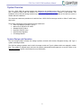
General Vehicle Requirements
Inadequate distance between the FSM and trailer (trailer gap) may result in damage to the FSM.
Always maintain adequate distance between the FSM and trailer (trailer gap) at all times. Failure to
maintain adequate distance between the FSM and trailer may result in death or serious injury.
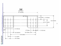
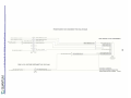
Dimensions
Minimum Distance Between Cab and Kingpin (A) ............................................................................ 106“ (2692mm)
Minimum Distance Between Cab and FSM (B) ....................................................................................... 5“ (127mm)
Minimum Distance Between FSM and Kingpin (C)* ............................................................................ 70“ (1778mm)
* Verify measurement with the 5th wheel in the forward most position. Trailers with non-standard (42” or 48”)
kingpins may require additional wheelbase and clearance.
Weight
FSM (Empty) .................................................................................................................................. 1700 lbs (771 Kg)
FSM (Full) .................................................................................................................................... 2500 lbs (1134 Kg)
Electrical Requirements
Voltage Range .......................................................................................................................................... 12-16 VDC
Nominal Current Draw .......................................................................................................................................... 2 A
Peak Current Draw ............................................................................................................................................ 3.5 A
BOC Electrical Connector ................................................................................................ Deutsch HDP30-18-14 PN
Coolant
Minimum Coolant Flow .............................................................................................................................. N/A GPM
Coolant Type ...................................................................................................... Glycol / Phosphate Based Coolant
Fitting Type / Connection ...................................................................................................................... 5/8“ Hose Bib
Antifreeze Protection .......................................................................................................................... <-40°F (-40°C)
Fuel
Fuel Outlet Connection ................................................................................................ -12 37° Flare, Stainless Steel
6
CNG Gen 1 BOC FSM Installation Manual
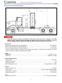
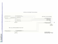
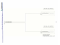
Exhaust
Minimum Distance Between Vertical Exhaust Stack and FSM (A) ......................................................... 5“ (127mm)
Minimum Distance Between Vertical Exhaust Stack Outlet and FSM (B) .............................................. 5“ (127mm)
Minimum Distance Between Horizontal Exhaust Stack and FSM (C) ..................................................... 8“ (203mm)
Minimum Distance Between Horizontal Exhaust Stack Outlet and FSM (D) ........................................ 12“ (305mm)
Dimensions
Maximum Distance Outside of Frame to Outside of Frame (A) ......................................................... 34.5“ (876mm)
Minimum Allowable Width ................................................................................................................ 33.75“ (857mm)
7
CNG Gen 1 BOC FSM Installation Manual
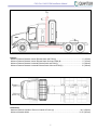
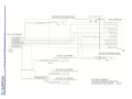
General FSM Specifications
The Gen 1 BOC FSM has three different base mounts which will vary in width. These mounts are defined below
and are identified with a -001, -003, and -005. You will need to confirm that the FSM width, which is identified by
the part number, fits the frame of the truck.
Dimensions
Depth of CNG Fuel Storage Module (A) ............................................................................................. 30.7“ (780mm)
Depth of CNG Fuel Storage Module with Handles (B) ....................................................................... 33.8“ (859mm)
Maximum Width Between Mounts (C) ................................................................................................ 34.5“ (876mm)
Width of CNG Fuel Storage Module (D) ........................................................................................... 84.3“ (2142mm)
Height of the CNG Fuel Storage Module (E) .................................................................................... 93.0“ (2362mm)
Width (C) / Part Number*
Width Between Mounts PACCAR 116353-001 .................................................................................. 34.2“ (869mm)
Width Between Mounts Volvo / Mack 116353-003 ............................................................................. 33.8“ (859mm)
Width Between Mounts PACCAR (1/2“ Crossover) 116353-005 ....................................................... 34.2“ (869mm)
* Refer to the Label Locator section in this manual for location information to the part number specific to the fuel
storage module.
8
CNG Gen 1 BOC FSM Installation Manual
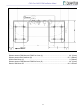
FRONT
Dimensions
Distance Between FSM Mount and FSM Front Cover (A) ..................................................................... 2.0“ (51mm)
Distance Between Bolt Centerlines (B) .............................................................................................. 15.7“ (400mm)
Width of Base Mount (C) ......................................................................................................................... 8“ (204mm)
Distance Between FSM Mount and FSM Rear Cover (D) ....................................................................... 2.0“ (51mm)
Depth of FSM Mount (E) .................................................................................................................... 10.5“ (267mm)
9
CNG Gen 1 BOC FSM Installation Manual
Installer Qualifications
To successfully install the FSM, the installer should meet or exceed the minimum requirements indicated below:
1. Must have the ability to read, understand, and follow the instructions contained in the CNG Fuel Storage
Module Installation manual.
2. Must have knowledge of all local, state, and federal regulations and standards applicable for installing CNG
systems.
3. Must have a basic understanding of CNG fuel system installations.
Tool Requirements
In addition to standard technician tools and safety equipment, the following tools and supplies are required to install
the fuel storage module:
Hand Tools
Tape Measure
1/8” Hole Punch
3/8” Torque Wrench (lb/ft)
1/2” Torque Wrench (lb/ft)
5/8” Open End Wrench
11/16” Drill Bit with 1/2" Shank
11/16” Crowfoot
11/16” Angle Open End Wrench
13/16” Angle Open End Wrench
13/16” Crowfoot
18” Socket Extension
Shop Equipment / Tools
Drill with 1/2” Chuck
9” Digital Caliper
Inert Gas 6K Cylinder w/ Regulator, Lines, and CNG fill nozzle
Lifting Straps or Chain (Rated to 3000 lbs+)
Electronic Gas Detector
Magnetic Base Drill Press (Recommended)
Fork Lift (Recommend)
Metal Base Mount Drill Template
Special Service Tools
Cylinder Installation Support Fixture
Fluid Requirements / Shop Supplies
Snoop® Leak Detection Fluid
Parker® O-Lube
Zinc Rich Primer
Fast Drying Enamel Paint
10w Oil
10
CNG Gen 1 BOC FSM Installation Manual
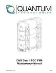
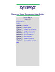
Components Locator
FSM System
1
2
3
4
5
1.
2.
3.
4.
5.
FSM Front Cover
PRD Vent Lines
CNG Cylinder Valve (Qty 3)
CNG Cylinder (Qty 3)
Fill Panel
11
CNG Gen 1 BOC FSM Installation Manual
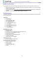
Fill Panel
1
1.
2.
3.
4.
2
3
4
CNG Pressure Gauge
1/4-Turn Manual Shut Off Valve
Standard NGV1 CNG Fill Valve
High Flow, ISO 14469-2, CNG Fill Valve
Fuel Gauge Module
1. Electrical Connector / Interface
2. Fuel Control Module
1
12
2
CNG Gen 1 BOC FSM Installation Manual
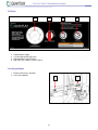
Safety Valves
1
2
3
4
1.
2.
3.
4.
CNG Fuel Storage Cylinder – Manual Valve (Top Cylinder)
CNG Fuel Storage Cylinder – Manual Valve (Middle Cylinder)
CNG Fuel Storage Cylinder – Manual Valve (Bottom Cylinder)
1/4-Turn Manual Shut Off Valve
13
CNG Gen 1 BOC FSM Installation Manual
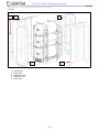
Covers
1
2
3
4
1.
2.
3.
4.
5.
5
Access Door
Front Cover
Right-Side Cover
Left-Side Cover
Rear Cover
14
CNG Gen 1 BOC FSM Installation Manual
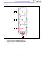
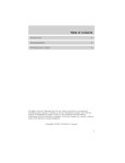
Line Identification
Lines from the fuel storage module bulkhead are
located below the FSM next to the electrical interface
connector.
4
The lines are identified below:
1. CNG Outlet (Regulated) - 5/8” 37° Flare
2. Coolant In / Out – 5/8” Bib
3. Coolant In / Out – 5/8” Bib
4. CNG Inlet
5. CNG Pressure Sensor
6. PRD Vent
1
2
3
Always have protective caps covering the lines when
they are not connected to the vehicle to prevent foreign
matter from entering the system.
5
6
Load Light Connector
The load lights have a pigtail connector at the base of
the cover to the left of center. The connector must be
disconnected whenever the rear cover is removed from
the BOC.
Power to the load lights is supplied through the main
electrical interface located at the base of the front
cover on the fuel storage module behind the fill panel.
15
CNG Gen 1 BOC FSM Installation Manual
Label Locator
Always replace any damaged or missing labels.
1
1
2
2
3
3
4
4
16
CNG Gen 1 BOC FSM Installation Manual
5
5
6
6
17
CNG Gen 1 BOC FSM Installation Manual
Packaging Contents and Assembly
The FSM will be shipped on a pallet and must be
handled and stored vertically. The system will be fully
assembled and will require disassembly of the rear
cover and side covers before installation.
The contents of the delivery will include:
1 Fuel Storage Module (Gen 1 BOC)
Frame Install Kit
o 16 Screws, Hex Flange, M16
o 16 Nuts, Crimp, Hex Flange, M16
o 16 Washers, M16
o 2 Shims, 1/16”
o 2 Shims, 1/8”
2 Hose Clamps, Coolant
1 Interface Harness
Accessories
The FSM will have several optional accessories available:
Description
Stub Out Pipe Kit for Slave Module
1/16” Shim (0.0625”, 1.6mm)
1/8” Shim (0.125”, 3.2mm)
10’ CNG Low Pressure Flex Hose
12’ CNG Low Pressure Flex Hose
18’ CNG Low Pressure Flex Hose
Part Number
116228
116161-001
116161-002
116574-003
116574-004
116574-006
18
Manual Reference
Slave Cylinder Connection
Shim Installation
Shim Installation
-
CNG Gen 1 BOC FSM Installation Manual
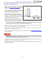
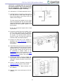
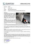
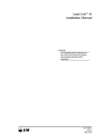
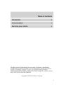
Module Lifting
Lifing the FSM with a single strap is not
recommended. Always use at least two straps
that are rated and capable of holding the FSM.
Failure to lift with two capable straps will
result in death or serious injury.
The fuel storage module has four (4) lift points
supplied, two under the cover and two that protrude
through the cover. It is recommended that the FSM be
lifted using all four supplied lift points to allow for
proper handling and ease of installation. The FSM may
be lifted by the two (2) exposed lift points only but the
assembly will not hang properly and may be difficult to
install. The chain or straps must exceed 3000 lbs
(1361kg) lifting capacity.
REAR COVER REMOVED
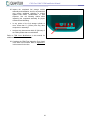
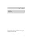
The FSM has a dry weight of 1700 lbs (771 Kg) and
will require lifting equipment that can safely sustain that
weight. The photo to the right shows a configuration
that can safely lift the FSM. This is not the only option
to lift the FSM, but it does permit the FSM to be
maneuverable during the installation process.
The front cover must remain on the FSM during the
installation process. The 2 lift points that protrude
through the front cover are highlighted in the photo to
the right. Use protective coverings so that the chain
does not damage the Class A paint finish on the cover
or the CNG cylinders.
FRONT COVER INSTALLED
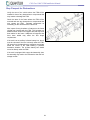
The total ceiling clearance recommended to lift the
FSM is 15 ft (4.6m). Be sure the shop has a lift and
adequate ceiling clearance to install the FSM onto the
frame of the truck. Lifting clearance will vary depending
on truck frame height and the type of lifting fixture
used.
19
CNG Gen 1 BOC FSM Installation Manual
Torque Specifications
Fuel Line
37° Flare (Stainless / Stainless) ..................................................................................................... 60 lb-ft. (81N.m)
Hex Flange
M6-1.0 (FSM Covers) .................................................................................................................... 62 lb-in. (70dN.m)
M8-1.25 (FSM Covers) .................................................................................................................. 62 lb-in. (70dN.m)
M12 .................................................................................................................................................. 63 lb-ft. (85N.m)
M12 w/ Stover Nut ......................................................................................................................... 81 lb-ft. (110N.m)
M16 FSM to Frame (10w Lubricant Required) ............................................................................ 180 lb-ft. (244N.m)
Cylinder strap nuts ................................................................................................................................... See Note 1
Note 1: The strap nut is tightened until the installed height of the spring on each end of the cylinder strap is 1.23”
±0.08” (31mm ± 2mm) with the cylinder pressure below 500 psi (34.5 bar). The straps for Gen 1 BOC are preset
during assembly and are not adjustable.
20
CNG Gen 1 BOC FSM Installation Manual
Vehicle Compatibility
The Gen 1 BOC FSM is designed for Class 7 and 8 trucks with a maximum frame width of as defined in the
General System Specifications. All clearances must be adhered to per the General System Specifications of this
manual.
Always comply with federal, state, and local regulations when installing the FSM onto a vehicle.
Frame Preparation
This FSM has been designed as a generic fuel storage module for Class 7 and 8 trucks. Any application deviation
may require modifications to the steps below. The installation instructions are intended to guide a knowledgeable
and experienced CNG technician through the necessary steps to install the FSM.
Be sure to inspect the frame for prior damage, rust, welds, areas missing paint, and/or reinforcement plates. These
indicators could mean that the frame’s structural integrity may be compromised.
Compliance of the installation to all federal, state, and local regulations is ultimately the responsibility of the
installer.
It is the responsibility of the installer to ensure the vehicle being equipped with the FSM is in good condition and
that installation of this system will not create a hazard or cause damage to the vehicle.
IMPORTANT: Before you begin the installation process of the fuel storage module, you should verify
the installed assembly will meet all your customer requirements and regulatory requirements that may
be applicable.
There are a number of considerations when determining where to place the FSM on the vehicle frame:
Will the width of the frame be within the mount specification range for the FSM?
Are there any heat sources in close proximity to the FSM?
Will there be enough clearance between the FSM and the trailer?
Are there any cross members or support structures that would interfere with the FSM?
Will any of the accessories interfere with the BOC installation?
Will an auxiliary battery storage unit located under the FSM need to be relocated?
Below are a few steps that will help you determine if the FSM can be successfully installed and meet all the
Quantum, regulatory, and customer requirements:
Step 1 – Measure Frame Width
Step 2 – Measure FSM Clearance
Step 3 – Inspect for Obstructions
Step 4 – Inspect for Heat Sources
Step 5 – Installation Checklist
Step 6 – Frame Drilling Guidelines
21
CNG Gen 1 BOC FSM Installation Manual
Step 1 Measure Frame Width
Verify the overall width of the fuel storage module will fit
in the allocated space and the area where the FSM is to
be installed is free of parts, brackets, bolts, or
components that may contact or damage the FSM. Verify
the width of the vehicle frame is large enough to accept
the FSM with appropriate clearance.
The overall dimensions for the FSM are contained in this
manual. Refer to General System Specifications in this
manual for additional information.
22
CNG Gen 1 BOC FSM Installation Manual
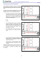
Step 2 Measure FSM Clearance
Confirm that the space between the cab and the
kingpin (A) meets the minimum requirement as
specified in the General Vehicle Requirements section
in this manual.
Verify the FSM will have adequate clearance from the
rear wall of the driver’s cab to the front of the FSM
assembly (B) and the FSM to the kingpin (C).
The FSM must maintain a minimum distance of 5”
(127mm) between the FSM and the rear wall of the
driver’s cab. The location where the FSM will be
mounted must have this minimum clearance or damage
to both the driver’s cab and FSM may occur.
REMOVE EXHAUST
The installer must first determine distances A, B, and C
and then fit the application to leave adequate clearance
to the vehicle components for service and assembly.
IMPORTANT: If the truck is equipped with an adjustable 5th wheel assembly, then place the assembly
into the forward most position when making the following measurements.
Measure 106” (2692mm) from the back of the driver’s cab down the frame rail to the kingpin (A).
determine if the truck has enough space to accommodate a FSM.
This will
Then, measure 70” (1778mm) from the kingpin up the rail towards the FSM. This is the minimum clearance
needed for the trailer with or without a reefer (C).
(B + C) – A = total allowable area for the FSM. Refer to the measurements in the General Vehicle Requirements
section of this manual.
Inadequate distance between the FSM and trailer may result in damage to the FSM. Always maintain
adequate distance between the FSM and trailer at all times. Failure to maintain adequate distance
between the FSM and trailer may result in death or serious injury.
The remaining area to mount the FSM will become important if the FSM system must be positioned to avoid
obstacles and heat sources mentioned in the upcoming chapters.
Before proceeding, the installer should consult all federal, state, and local regulations to ensure the installation will
comply with all requirements.
23
CNG Gen 1 BOC FSM Installation Manual
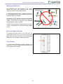
Step 3 Inspect for Obstructions
Verify the area of the vehicle where the FSM will be
installed is clear of any obstructions or components that
may contact or damage the FSM.
Check the area of the frame where the FSM will be
mounted and note any obstructions or components that
may contact the FSM.
Relocate components as
necessary per the manufacturer’s instructions.
Also inspect for any brackets or features on the frame
rail that may interfere with the FSM. This includes any
additional inner and/or outer support rails that may have
been added to the frame. Additional rail supports that
have been added may affect the bolt length
requirements.
If the truck has an auxiliary in-frame battery box, then it
must be relocated if the box is directly under the FSM.
Off gases from the batteries may otherwise accumulate
within the covers of the FSM creating a potential
hazardous situation. The in-frame battery box should
never be directly under the FSM.
If the truck is equipped with a pogo stick assembly, then
the assembly may need to be relocated to clear the fuel
storage module.
24
CNG Gen 1 BOC FSM Installation Manual
Step 4 Inspect Heat Sources
Due to the construction of the FSM and the location of
the CNG cylinder relief devices, Quantum has an
additional requirement to add additional heat shielding if
a heat source is within 5“ (127mm) of the CNG cylinder
covers or to relocate the heat source.
If the heat source is within 8” (204 mm) of the FSM
cylinders, adjustments MUST be made in the installation
to increase the distance between the heat source and
the FSM.
See your truck equipment supplier for heat shielding
solutions.
25
CNG Gen 1 BOC FSM Installation Manual
Step 5 Installation Checklist
Refer to the illustrations and dimensions in the General System Specifications section of this manual to answer the
items on the checklist below.
Distance from outside of rail to the outside of rail .......................................................................................... ______
Gap between the FSM mount and the outside of rails ................................................................................... ______
Will shims be required? .................................................................................................................. Circle: YES / NO
Distance from the back of the driver’s cab to the FSM ................................................................................... ______
Does this distance exceed the minimum specification? ................................................................. Circle: YES / NO
Distance from the FSM to the kingpin ............................................................................................................ ______
Does this distance exceed the minimum specification? ................................................................. Circle: YES / NO
Verify the locations of the holes to be drilled in the frame are appropriate .................................... Circle: YES / NO
Verify the actual size of the drill templates printed from the manual (if used) ................................ Circle: YES / NO
Verify all other measurements to ensure the FSM will fit the target area ....................................... Circle: YES / NO
Have all sources for obstructions been resolved? .......................................................................... Circle: YES / NO
Have all sources for heat been resolved? ...................................................................................... Circle: YES / NO
You will need the following information available to ensure the system, once installed, will be a safe and legal
installation:
Vehicle frame width (outside of frame to outside of frame).
Distance from the back of the driver’s cab to the FSM.
Distance from the FSM to the kingpin.
Specifications for the fuel storage module. Refer to General System Specifications in this manual.
Once you have determined that the fuel storage module can be properly installed and meet all the necessary
requirements, you can proceed with drilling the frame to support the FSM.
26
CNG Gen 1 BOC FSM Installation Manual
Step 6 Frame Drilling Guidelines
The drilling of the frame side member presents no unusual difficulty. Standard high speed steel drills of good quality
will serve provided they are sharpened properly and not overheated during sharpening or use.
It is recommended to follow these guidelines when drilling holes in vehicle frames:
Use existing holes whenever possible.
Do not weld filler pieces into any unused holes of the chassis frame.
Do not flame cut holes.
Do not drill holes into the restricted areas of the frame rails.
It is not recommended to remove the factory installed huck bolts.
To prevent the forming of cracks from the drilled holes, the holes must always be deburred by 45°
chamfering (on both sides) and subsequently treated with primer and paint.
Add hardware to the existing / open holes and torque to specification.
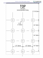
Hole Location Guidelines
The following recommendations should be considered
when determining where to drill the holes in the frame
members:
Never drill holes in the flanges of the frame
members.
Never drill holes in the tapered end of the rear
frame cutoff.
The drilling of holes less than 2” (51mm) from a
bend in the chassis frame is not recommended.
Maintain a minimum distance of 2.8 times the
diameter of the largest hole between holes.
There should not be more than three holes
located on a vertical line.
Bolt holes should be no larger than is required
for the size of bolts being used, in no instance
larger than 11/16 (17.5 mm).
If reinforcements are used, avoid drilling holes
closer than 2.0 inches (51 mm) from the ends
of the reinforcement.
27
CNG Gen 1 BOC FSM Installation Manual
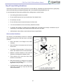
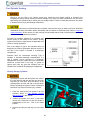
FSM Base Mount Hole Location Considerations
In some instances, there may be pre-existing holes
drilled into the frame. If pre-existing holes are in the
location where the base mount of the FSM is to be
mounted, then the following should be addressed:
Pre-existing holes in the frame should be marked
and drilled into the FSM base mount. The drill
should be the same size as the pre-existing hole
in the frame. Do not enlarge any holes. Insert
fasteners through the holes and torque the
fasteners to appropriate specifications. Preexisting holes drilled into the FSM base mount
with fasteners does not substitute use of the M16
fasteners provided with the installation kit.
1
2
3
4
If a 11/16” base mount hole (one that uses the
M16 bolt from the installation kit) needs to be
relocated, then mark and drill a hole in the new
location following the Hole Location Guidelines in
this manual. There must be one 11/16” hole or
equivalent in each of the four quadrants as
shown in the illustration on the right.
A 5/8” bolt (Grade 8 or better) is a suitable replacement
to the M16 bolt supplied with the installation kit if
required.
For special considerations, contact Quantum Technical
Assistance at 800/816-8691.
28
CNG Gen 1 BOC FSM Installation Manual
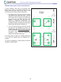
FSM Installation
1. Secure the truck making sure the wheels are
chocked and is on level ground.
2. Locate the FSM mount positions on the vehicle
frame
following
the
General
System
Specifications mentioned in this manual.
3. Verify that the FSM will have adequate clearance
around all sides and from the kingpin.
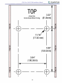
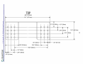
4. Mark the hole locations. The bolt pattern and
template for the FSM mount can be found in
Appendix A. Make sure that the bolt pattern is
level with the frame and not level with the
ground. Measure the bolt pattern only to be level
to the frame.
5. Confirm there are no obstructions on the frame
and ensure the area inside the frame is clear of
components or lines that may be damaged during
the drilling operation.
6. Drill the marked holes for the FSM mounts. The
holes should be drilled to 11/16” (17.5mm) or to
match the existing holes.
7. Clean any burrs from the holes and coat the
holes with a zinc rich primer or equivalent anti
corrosion coating.
The fuel storage module covers are painted and are
categorized as Class A finish. Follow all protective
guidelines when working with Class A finishes.
8. Unpack the FSM from its shipping container. The
FSM will be fully assembled within the container.
9. Unscrew the rear FSM cover and side covers.
Disconnect the electrical connectors for the load
lights on the rear cover. There is a connector at
the base of the rear panel which separates the
load lights from the main harness of the FSM.
10. Remove the grab handles and associated
hardware. The rear cover is painted and has a
Class A finish, it will take 2 persons to safely
remove the rear cover. Finally, carefully set the
covers in a location where they will not get
damaged.
29
CNG Gen 1 BOC FSM Installation Manual
11. Locate the 4 lift points on the FSM. Refer to the
Module Lifting section within this manual for
more information.
12. Connect the chain, straps, or lifting fixture to the
rear lifting points.
13. Connect the chain, straps, or lifting fixture to the
front lifting points. The front cover will still be
on the FSM so care must be taken not to
damage the Class A finish of the front cover.
14. Using a minimum of 2 people, position the FSM
onto the frame of the truck. Align the holes on
the FSM with the holes drilled into the frame.
REAR COVER REMOVED
The FSM has been approved to be installed with the front of the FSM facing forward. The correct
installed position can be confirmed with the fill panel on the driver’s side of the frame. Failure to
install the FSM in the correct approved position may result in death or serious injury.
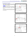
15. Slide one side of the frame so that it is flush
with the FSM base mount. The other side of
the frame may have a gap that exceeds 1/16”.
If the gap is greater than 1/16”, then a shim will
need to be installed.
Insert the appropriate number of shims until the
gap is less than 1/16”. Shims must be installed
equally to both mounting flanges of the base on
the same side of the vehicle.
It may be necessary to match drill the shims to
the frame and base mount.
There are (2) 1/8” shims and (2) 1/16” shims
included with the FSM kit. Additional shims can
be purchased if required. Part numbers for
shims can be found in the Accessories section
of this manual.
30
CNG Gen 1 BOC FSM Installation Manual
IMPORTANT: If existing holes are to be used,
the supplied hardware may not be sufficient for
full nut engagement. New hardware may be
required if additional length is necessary.
16. Lubricate the 11/16” both threads with 10w oil.
17. Install the fasteners through the mount holes on
the FSM and the holes drilled through the
frame. Each fastener must include a bolt, flat
washer, and a locking nut.
The bolts should be installed from the frame
side of the assembly with the nuts and washers
against the FSM mounts. Always torque the nut
versus the bolt when possible. Tighten to 180
lb-ft (244 N.m).
Do not use a pneumatic impact tools to install
any hardware.
18. Connect the coolant lines to the regulator using
the two clamps provided with the installation
kit. The hot coolant line must be placed on the
IN line port. The cool line must be connect to
the OUT line port. The lines may need to be
trimmed, routed, and clamped properly.
19. Connect the CNG line to the regulator as
identified in the Line Identification section of
this manual. Be sure to route and secure the
lines properly.
20. If the FSM is being connected to another CNG
cylinder install the stub out pipe kit for the slave
cylinder at this time. If not proceed to the next
step. The slave cylinder stub out pipe kit can
be purchased if needed. Refer to the
Accessories section of this manual for part
numbers. Details can be found in the Slave
Cylinder Connection section in this manual.
21. Connect the interface harness supplied with
the installation kit to the Deutsch HDP24-1814PN-L017 electrical connector on the front of
the FSM.
22. Perform a Start-Up Procedure following the
Start-Up Procedure section of this manual.
23. Install the rear cover. Tighten fasteners to 62
lb-in (70dNm).
24. Install the side covers and torque to 62 lb-in
(70dNm).
31
CNG Gen 1 BOC FSM Installation Manual
25. Inspect the completed fuel storage module
assembly and installation; look for any areas that
may require additional shielding to protect
against road debris, contamination, or heat
exposure. Use the following criteria when
inspecting the completed assembly for proper
clearances and shielding:
Is any portion of the fuel storage cylinder or
cover closer than 5“ (127mm) from any other
component or assembly?
Are there any heat sources within 8” (204 mm) of
the FSM cylinders that are unshielded?
Refer to FSM Cover Modifications in this manual for
additional information and instructions.
26. Complete the FSM Final Inspection Form found
in the back of this manual. Refer to Appendix D
in this manual for the form.
32
CNG Gen 1 BOC FSM Installation Manual
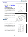
Slave Cylinder Connection
Some FSMs may be ordered with a slave cylinder
assembly which will require installation. A slave cylinder
stub out pipe is available for purchase in the
Accessories section of this module.
The T-Connection will be fitted with an O-ring face seal
cap. Remove the cap and connect the slave cylinder
stub out pipe to the T-Connection. Attach all support
hardware.
Once the stub out pipe has been installed, a line must
be fabricated to connect the stub out pipe on the FSM to
the slave cylinder.
33
CNG Gen 1 BOC FSM Installation Manual
FSM Cover Modifications
Modification of the fuel storage module covers may result in creating a potentially hazardous condition. It is not
recommended to modify the covers. Any cover modification may compromise the integrity of FSM covers.
Once you have determined the FSM will physically fit in the target area on the vehicle, you must also inspect for
components or brackets on the frame that may interfere with the FSM covers or may even become an abrasion
hazard for the CNG cylinder.
You must also evaluate the environment for heat sources, the FSM should be mounted at least 5” (127mm) from
any heat source. In the event a heat source is in close proximity to the FSM covers or the cylinder is exposed to
direct heat from the heat source steps MUST be taken to protect the FSM and the CNG cylinder.
NFPA 52 States:
6.3.2.1 Fuel supply containers shall be protected with a means to prevent damage that can occur due to road
hazards, loading, unloading, direct sunlight, exhaust heat, and vehicle use, including accidental cargo leakage.
6.3.7 Fuel supply containers located less than 8 in. (200 mm) from the exhaust system shall be shielded against
direct heat.
Important: Failure to adequately insulate or protect the fuel storage module and its components may result in
damage to the fuel storage module or its components resulting in potential fuel leakage.
It is the responsibility of the installer to ensure that the fuel storage module and its components are protected
against debris and direct heat sources. The following guidelines must be observed before the vehicle is operated
using this fuel storage module.
Heat Sources:
Inspect the FSM cover clearances per the General
System Specifications section in this system.
If possible, move all heat sources away from the fuel
storage module to prevent heat transfer.
The FSM should be thoroughly shielded from any heat
sources that may radiate to the fuel storage module.
34
CNG Gen 1 BOC FSM Installation Manual
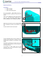
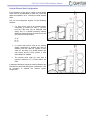
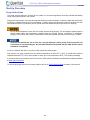
Vertical Exhaust Stack Configuration
In the illustration to the right, a number of heat related
issues need to be addressed to make this a safe and
approved installation for a vertically mounted exhaust
stack.
See your truck equipment supplier for heat shielding
solutions.
If a heat source such as an exhaust system
component is located less than 5” (127mm)
from any FSM cover (B), an additional heat
shield, and or a thermal insulating material
MUST be placed between the heat source and
the CNG fuel storage module.
A – 8”
B – 5”
C – 5”
If a direct heat source such as an exhaust
system component is located less than 8”
(204mm) from the CNG fuel cylinder or PRD
valve (A), and there is no shield between the
heat source and the CNG cylinder, a heat
shield MUST be installed.
The exhaust stack outlet (C) must have a
minimum clearance of 5” (127mm) above the
FSM.
If adequate clearances cannot be achieved between the
FSM and the vehicle exhaust system components, it will
be necessary to relocate the exhaust system
components.
35
CNG Gen 1 BOC FSM Installation Manual
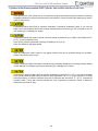
Horizontal Exhaust Stack Configuration
In the illustration to the right, a number of heat related
issues need to be addressed to make this a safe and
approved installation for a horizontally mounted exhaust
stack.
A horizontal heat shield is standard on all units.
However, see your truck equipment supplier for heat
shielding solutions if more heat shielding is required.
If a heat source such as an exhaust system
component is located less than 5” (127mm)
from any FSM cover (B), an additional heat
shield and or a thermal insulating material
MUST be placed between the heat source and
the CNG fuel storage module.
A – 8”
B – 5”
C – 12”
If a direct heat source such as an exhaust
system component is located less than 8”
(203mm) from the CNG fuel cylinder or PRD
valve (A), and there is no shield between the
heat source and the CNG cylinder, a heat
shield MUST be installed.
The exhaust stack outlet (C) must have a
minimum clearance of 12” (305mm) behind the
FSM.
You will note that the exhaust components are
positioned under the FSM covers allowing the
CNG cylinder to be subjected to direct heat
rising from the exhaust.
If this opening is not properly shielded, the fuel
storage module and/or components could be
damaged.
CHANGE PICTURE
If adequate clearances cannot be achieved between the
FSM and the vehicle exhaust system components, it will
be necessary to relocate the exhaust system
components.
36
CNG Gen 1 BOC FSM Installation Manual
Mounting to FSM Covers
No modifications are recommended to the covers.
Altering the covers may compromise the cover’s
integrity to protect the fuel storage module.
If a fastener absolutely must be added or replaced in
the fuel storage module covers, the fasteners must not
contact the CNG fuel cylinders.
Any fastener that is added to the CNG fuel storage
module covers shall not point toward the CNG fuel
cylinder. In the event of an accident, these fasteners
may damage the CNG fuel cylinder.
DO NOT USE self drilling or pointed fasteners to secure
covers or components to the CNG fuel storage module
covers.
Debris and Impact Protection
An opening has been made in the FSM cover for
access to the interior. If the cover is not secured or left
open, debris may enter the interior of the and potentially
damage the CNG cylinders or FSM components.
Cover Damage
If a cover becomes damaged, contact Quantum for a
replacement. Be sure to have the serial number for the
cover available when ordering.
37
CNG Gen 1 BOC FSM Installation Manual
Start-Up Procedure
Purge Instructions
The purge process dilutes the contents of the cylinder to a level that significantly limits the potential flammability
range of any gases present in the cylinder.
Purging the CNG cylinder is an important step that should be performed before a cylinder is filled with CNG and or
any time the cylinder has been open to atmosphere. Cylinder purging should also be performed to dilute the CNG
concentrations within the cylinder any time a cylinder has been drained and will require service or shipping.
Do not allow atmosphere to enter the fuel storage cylinder during purging. The fuel storage cylinder pressure
should remain higher than atmospheric pressure during the purging process. Introduction of atmosphere
(oxygen) in the cylinder may create a combustible mixture that if ignited, may result in serious injury or death.
Quantum recommends the use of clean, dry, inert gas (Nitrogen, >99.5% purity) for this procedure. If it
is necessary to use flammable gas, this procedure should be performed after the CNG cylinder vehicle
installation is completed
Prior to the initial fill with CNG, or any service the cylinder should be purged.
Only perform the purge process when the ambient temperature is above 0⁰F (-18⁰C). If cylinder was stored at
temperatures below 0⁰F (-18⁰C) allow cylinder to warm up to room temperature >60⁰F (15⁰C) before proceeding.
A recommended purge procedure can be found in the CNG Cylinder Installation and Maintenance Manual available
at www.qtww.com/service.
To vent the purge gas from the fuel storage module, refer to the Fuel Cylinder Venting procedure in this manual.
38
CNG Gen 1 BOC FSM Installation Manual
Cylinder Initial Pressurization/CNG Cylinder Valve Initial Interface Leak Test
Never pressurize a CNG cylinder that is not restrained by approved brackets properly mounted or otherwise
acceptably restrained to prevent movement while under pressure. Failure to observe this warning may result in
death or serious injury.
Compressed Natural Gas (CNG) is extremely flammable. If something accidentally ignites it, you could be
badly burned. Keep sparks, flames and smoking materials away from natural gas. Do not smoke if you are
near natural gas or refueling your vehicle.
Compressed Natural Gas (CNG) is stored in the fuel cylinder at pressures up to 3,600 psi (24.8 MPa) at 70°F
(21°C). To prevent personal injury:
Never fill to a pressure greater than 3,600 psi (24.8 MPa) at 70°F (21°C).
Never fill a leaking or damaged cylinder.
Verify any equipment used is rated for the highest pressure that can be generated during the procedure.
Failure to do so may result in injury.
Failure to follow the initial pressurization instructions may irreversibly damage the fuel storage cylinder, leading
to CNG leakage. Fuel leakage may result in personal injury or damage to the vehicle.
Performing this procedure when the CNG cylinder temperature is less than 0⁰ F (-18⁰ C) may result in damage
to the cylinder. Allow the CNG cylinder to warm to room temperature >60⁰ F (13⁰ C) for a minimum of 12 hours
before pressurizing. If ambient conditions where test is performed are less than 0⁰ F (-18⁰ C), complete the
procedure within ½ hour after removing cylinder from room temperature environment. Failure to follow this
requirement may result in injury.
39
CNG Gen 1 BOC FSM Installation Manual
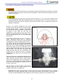
When a cylinder is pressurized from empty, a
small quantity of AIR (not fuel) is compressed out
from between the liner and composite shell. This
may cause bubbling around the surface of the
shell and/or the end bosses during leak tests.
This is a normal condition known as
“permeation” and the bubbling should subside
typically within 30 minutes. If there is any doubt
leave the cylinder pressurized overnight. If the
pressure is unchanged and the bubbling has
subsided, this is considered normal permeation
of entrapped air.
You may also observe some cracking or popping
sounds coming from the cylinder during the
initial pressurization. If the liner has settled away
from the shell during shipping, some cracking or
popping noises may be heard during the initial
fill; you may also be hearing the shell of the
cylinder settling as it is pressurized. If there is no
damage to the cylinder, and no fuel leakage is
detected, there should be no concern
pressurizing the cylinder.
If a leak is detected, immediately stop filling the system. Failure to follow this instruction may result in serious
injury or death.
If while filling the vehicle a leak is detected through the fill valve that is not currently being used, or anywhere else in
the system, the fill process should be stopped immediately. They system should not be filled until the leak or
leaking component has been repaired or replaced.
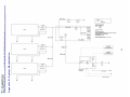
The recommended steps for this procedure are outlined in order below:
1. Ensure that the fuel storage module is properly installed in a vehicle or retained in a appropriate test fixture
before proceeding.
2. Connect the gas supply to the CNG cylinder or the system fill valve.
3. Slowly fill to 30 bar (430 psig) while listening for gross leakage. Re-test and repair any leaks discovered.
When leak test is successfully passed, vent the system through the vent circuit. These steps validate the
equipment setup and operation for testing the CNG cylinder valve/PRD interface. Test all connections and
interfaces in the circuit with a liquid leak test fluid. Observe all connections and interfaces for bubble
formation over a two minute period. If no bubbles are present, continue with procedure. If bubbles are
found, close the supply valve and vent the system by opening the vent circuit ¼ turn valve and repair any
leak(s) before proceeding.
4. Increase the cylinder pressure to 100 bar (1450 psig). Re-test and repair any leaks discovered. When leak
test is successfully passed, vent the system through the vent circuit. These steps validate the equipment
setup and operation for testing the CNG cylinder valve/PRD interface. Test all connections and interfaces
in the circuit with a liquid leak test fluid.
5. If inert gas was used for this procedure, then vent the cylinder following the Fuel Cylinder Venting
procedure in this manual.
40
CNG Gen 1 BOC FSM Installation Manual
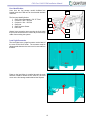
Filling your Fuel Storage Module
To ensure proper system operation, it is recommended that the CNG system is filled with CNG that meets SAE
J1616 specifications.
Compressed Natural Gas (CNG) is extremely flammable. If something accidentally ignites it, you could be
badly burned. Keep sparks, flames and smoking materials away from natural gas. Do not smoke if you are
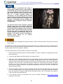
near natural gas or refueling your vehicle.
Compressed Natural Gas (CNG) is stored in the fuel cylinder at pressures up to 3,600 psi (24.8 MPa) at 70°F
(21°C). To prevent personal injury:
Never fill to a pressure greater than 3,600 psi (24.8 MPa) at 70°F (21°C).
Never fill a leaking or damaged cylinder.
The fill valve panel is located on the fuel storage module end panel assembly.
The fuel system is equipped with two fill valves; a standard NGV 1 compliant 3600 psi fill valve (1) and a high flow,
3600 psi, ISO 14469-2 compliant fill valve (2). Either fill valve may be used with no additional actions required by
the system operator.
1
41
2
CNG Gen 1 BOC FSM Installation Manual
If a leak is detected, immediately stop filling the system. Failure to follow this instruction may result in serious
injury or death.
If while filling the vehicle a leak is detected through the fill valve that is not currently being used, or anywhere else in
the system, the fill process should be stopped immediately. They system should not be filled until the leak or
leaking component has been repaired or replaced.
Because CNG is a gas, the amount stored in the CNG fuel cylinder depends on pressure and temperature. The
CNG fuel system uses a service pressure of 3,600 psi (24.8 MPa) at 70°F (21°C).
Many CNG fuel stations in the United States presently operate at this pressure. However, some stations in the
United States and all stations in Canada presently operate at 3,000 psi (20.7 MPa). This lower refueling pressure
will reduce the capacity of your fuel storage system by about 15%.
Also a “fast fill” station heats and expands the natural gas during refueling. A fast fill can reduce the capacity of your
fuel storage system by about 15%. A system refueled using a “slow fill” overnight dispenser is not subject to this
condition and should receive a full fill.
Fast filling using the high flow fill receptacle may also result in a decreased fuel capacity due to the additional heat
generated in the cylinder by the faster filling times.
Some fast fill CNG fuel stations provide temperature compensated refueling. This means that the fuel station will
automatically adjust refueling pressure if the outside temperature is very hot or very cold. For example, on a very
hot day (100°F (38°C)), the fuel station may provide a refueling pressure of about 4,000 psi (27.6 MPa). This is
normal and does not indicate a problem.
To fill your vehicle with CNG fuel, do the following:
1. Turn off the engine and set the parking brake.
2. Turn off all equipment that may produce heat, sparks or flame.
3. Remove the fill valve cap and any debris from the fill valve.
4. Inspect the fill valve O-ring. Make sure the O-ring is seated in the groove. Never connect the fill nozzle to
the valve if the O-ring is missing or damaged. Refer to Fill Receptacle O-Ring Inspection in this manual.
Attempting to fill a Compressed Natural Gas (CNG) fuel system that has a missing or damaged O-ring is
dangerous. Natural gas can leak. If the natural gas is accidentally ignited, you or others could be injured.
Replace the O-ring before filling the cylinder.
5. Connect the CNG fill nozzle to the fill valve and follow the instructions displayed on the fuel dispenser.
6. When finished fueling, disconnect the fill nozzle, return it to the dispenser, and put the fill valve cap back on
the fill valve.
42
CNG Gen 1 BOC FSM Installation Manual
Low Ambient Temperature Vehicle Refueling
Never pressurize a CNG cylinder that is not restrained by approved brackets properly mounted or otherwise
acceptably restrained to prevent movement while under pressure. Failure to observe this warning may result in
death or serious injury.
Performing this procedure when the fuel storage module is less than 0⁰ F (-18⁰ C) may result in damage to the
components within the FSM. Allow the FSM to warm to room temperature >60⁰ F (13⁰ C) for a minimum of 12
hours before pressurizing. Failure to follow this requirement may result in minor or moderate injury as well as
damage to components.
Fueling in low ambient temperatures may cause
freezing concerns and potential flow restrictions within
the fuel storage module. Fueling in low ambient
temperatures may result in potential flow restrictions as
ice begins to form inside the fuel lines and
components. In some cases, the fuel flow may be
restricted or entirely blocked due to ice build-up. If the
lines are blocked with ice, the ice must thaw before
flow resumes.
Cold ambient temperatures may have an effect on
system components causing them to temporarily
change size and shape. Quantum fuel storage modules
are designed to operate at temperatures as low as 40°F (-40°C). Both the rate of fueling and cold ambient
temperatures may drop the temperature within the FSM
below -40°F (-40°C). When this happens, the soft parts
that seal the system may be lose their ability to seal
against metallic components which may have changed
size and shape. The CNG within the system may
escape past the seals and out to atmosphere. Gas
escaping past the seals will create a dangerous
condition and may damage the fuel storage module
components.
Filling at a slower rate in cold ambient temperatures will
make it less likely for components to change size and
shape. Faster fill rates will create a larger pressure
drop which will significantly lower the temperature of
the fuel as it passes through the system. Faster fill
rates may result in dropping the temperature beyond
the -40°F (-40°C) limit.
Also, the quality of fuel has an effect on line freezing.
Quantum builds all fuel storage modules to be
compatible with SAE J1616 quality CNG.
SAE J1616 1.0 - Water content and other corrosion precursors, heavier hydrocarbons which may condense
within the fuel container, particulate matter, oil and energy content need to be controlled in order to minimize
corrosion and provide satisfactory low-temperature vehicle operation, performance, and emissions levels.
43
CNG Gen 1 BOC FSM Installation Manual
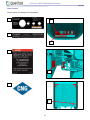
Refueling Problems
If the system cannot be refueled, check for the following:
The refueling system is not operating properly
o Refer to the refueling system operating instructions.
Refueling nozzle not properly engaged on the fill receptacle.
o Verify nozzle is fully engaged.
Cylinders already full.
o Verify CNG level in the cylinders using the pressure gauge.
The cylinders have higher pressure than the refueling system.
o Check the system pressure available from the refueling system and check it against the CNG pressure
in the cylinders.
If the items above have been checked and the system still will not take fuel, the system may require service.
44
CNG Gen 1 BOC FSM Installation Manual
Leak Checking the System
CNG is extremely flammable. If something ignites it, you could be severely burned.
Keep sparks, flames and ignition sources a minimum of 5 meters from CNG.
Ensure work area is well ventilated.
Always wear proper eye and hearing protection when working with pressurized gas.
Use explosion proof drop lights when working on gaseous fueled systems.
Failure to follow these basic safety guidelines may result in serious personal injury or death.
Before proceeding with this or any repair or
maintenance, read and understand the Important
Safety Information contained in the front of this
manual.
Use this procedure if a CNG fuel system leak is
suspected. The system can be checked for leaks after
initial power-up, at idle or while the system is
operating. Always leak check the fuel system after any
service that disturbs fuel carrying components has
been performed.
CNG gas is lighter than air and will rise. When using a
hand held detector, always check above lines and
fittings for best results.
1. Start the system to ensure all fuel lines are
pressurized.
IMPORTANT: When leak checking a system is
it strongly recommended that the high
pressure side is checked at several pressure
points (i.e. 500 psi, 1500 psi, 3000 psi, 3600
psi) as leaks may be present at lower
pressures and not at higher pressures.
2. Check the fuel system for leaks by using a
CNG gas detector, ultrasonic leak detector, or
Snoop®. If using a gas detector, run the
detector’s probe along the top of all lines,
joints, and fittings. Any leaks detected should
be repaired before the unit is returned to
service.
45
CNG Gen 1 BOC FSM Installation Manual
Fuel Cylinder Venting
Failure to use an orifice in the venting system may subject the fuel storage module to extremely low
temperatures during venting resulting in severe damage to (or failure of) these components. Use the orifice
specified by this procedure when venting the fuel storage module. Failure to follow this instruction may result
in death or serious injury and damage components.
If proper procedures are not followed during fuel cylinder venting serious injury or death could occur. Read and
understand all safety information before proceeding with the release of pressurized gas. Refer to Important
Safety Information in this manual. It is also strongly recommended that the local fire authority be consulted to
ensure all local regulations are followed.
All CNG Fuel Cylinders installed in an enclosed area
require venting to the outside of the vehicle. Venting
systems must meet the requirements of applicable local
codes or venting regulations.
Due to the design of Type 4 fuel cylinders there will
always be low levels of permeation that may result in a
fuel odor in the vehicle if mounted in a passenger
compartment.
Quantum does not recommend mounting Type 4
cylinders in enclosed passenger compartments. If a
type 4 cylinder will be mounted in a passenger
compartment, the entire cylinder and valve connections
should be covered with a vent “bag” or system to
capture and route any gas that escapes from the
cylinder to the outside of the passenger compartment.
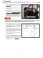
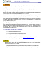
Venting Storage Cylinders
Operating the system with the system vent valve in
the open position and with the end cap removed,
may result in a fuel leak; verify the valve is in the
closed position and the end cap is secure before
filling or operating the system. Failure to follow this
instruction may result in serious injury or death.
1. Close the manual shut off valves on all fuel
cylinders. Refer to Fuel Storage Cylinder
Manual Shut-off in this manual.
2. Confirm the system vent valve (1) has been
turned to the clockwise so that the handle is
perpendicular to the line. This is the closed
position.
1
3. Remove the valve port end cap (2) on the outlet
port.
46
2
CNG Gen 1 BOC FSM Installation Manual
The vent hose must be equipped with a 0.042”
(1.06mm) orifice to prevent damage to the
cylinder valve.
4. Connect the vent line.
5. Open the manual shut off valves on the fuel
cylinders to be vented.
6. Slowly open the system vent valve by turning the
valve handle counter-clockwise so that the
handle is parallel with the vent line.
7. Drain the fuel cylinder to approximately 10 psig ±
5 psig (1.7 bar ±0.3 bar).
8. If the cylinder valve is to be serviced, purge the
remaining CNG from the fuel cylinder. Refer to
Purge Instructions in this manual.
9. After the venting and purge procedures are
complete, verify the manual shut off is closed by
turning the valve clockwise until it stops.
10. Close the system vent valve (1) so that it is
perpendicular to the line as shown.
11. Remove the vent line.
12. Reinstall the valve port end cap (2) and torque to
22 lb-ft (30 Nm).
47
1
2
CNG Gen 1 BOC FSM Installation Manual
Appendix A – FSM Mount Templates
-z
.-..
O'I
N
°'
°'
~
00
'-.J •
3
\0
:::
.-..
N
Ow
O'I
o.
~
-
-i
Vl
0 _.
o~
I0
I
3 °' 3 °'
~~ ~~
V"
n
)>
-I
0
-0
I
m
...........
j
.--..
O'I
N
3
Vl
/'
Vl •
3 ~
, '-' - - ( f ) - - - ( f ) -
.-..
N
0
00
~ ·
j
8
3
...........
3
~
~w
3~
~ "'
_'.._
' _ __.__
, _ _ _--i,_
· -
______ ,,
___._
I
I ~_.
I
I
I
~S
I/~~
-----(£)--- - ---(£)I
I
~~~,------f----------~~
_____
......___
j
1
'N
.....
°'3 Vi_.
'-.J 0
-
-
~
48
~
'
-
-
CNG Gen 1 BOC FSM Installation Manual
TOP
Actual Size
Do Not Scale When Printing
3.22"
(81.Bmm)
-ffi11 /16"
(17.50 mm)
5.90"
(150.0mm)
3.94"
(100.0mm)
-ffi1
49
TOP
(NOT TO SCALE)
t
I
I
I
I
I
I
I
I
I
I
I
I
\... I
I
I
-EB - EB - EB
-EB - EB - EB
-EB - EB - EB
I
I• • I
2~ 11 1 • \.,I•
0
I
I
I
I
I
I
I
I
I
I
I
I ;
I
-
-
EB - EB - EB-.-
-
EB - EB - EB-.1.97" (50mm)
~ ~ II I
a~
I
EB - EB - EB- .-
"\.
--
:J ~
I
-
,l
8.02" (203.8mm)
~~
I
EB - EB - EB- .-
-
-EB - EB - EB
1.54" (39.1mm)
•I
3.94" (1 OOmm)
19.69" (500mm)
1.97" (50mm)
3.94" (1 OOmm)
3.2" (81.82mm) -
1-
-
-
t
'.
1.97" (50mm)
..
i
"
3.94" (100mm)
..
10.5" (266 .?mm)
+ 5.91" (150mm)
50
CNG Gen 1 BOC FSM Installation Manual
1~
26.7" (678.2mm)
l
',
1.54"(39.1mm)
CNG Gen 1 BOC FSM Installation Manual
TOP
Actual Size
Do Not Scale When Printing
3.2" (81 .82mm)
- EB
/EB
11 /16"
(17.50mm)
1.97" (50mm)
-EB
1.97" (50mm)
- EB
EB
1.97" (50mm)
...__ EB
EB ~
1.97" (50mm)
EB
1.97" (50mm)
EB _ _ _ ._ _.
. . _____ L ________ I________ J _____ ..I
I
51
TOP
(NOT TO SCALE)
I
I
........
I
I
I
.--EB - EB - EB
I
I
I
I
I
I
0
I
I
I
I
I
I
-
-
\
EB - EB - EBI
I
I J
1.97" (50mm)
--
•
i
. 472·r mm)
1.54" (39.1mm)
.1.
~~
a~
I
EB - EB - EB- ~
}
-- -
1.97" (50mm)
3.94" (1 OOmm)
- -- --
3.94" (1 OOmm)
19.69" (500mm)
-
<( Z
:J ~
I
t
3.2" (81.82mm) ,__ 2.36" (60mm)
-
8.02" (203.8mm)
~~
I
EB - EB - EB-
-
.--EB - EB - EB
.--EB - EB - EB
\. I
I
I
........
-
1.54" (39.1 mm)
9.23" (234.5mm)
52
CNG Gen 1 BOC FSM Installation Manual
- -- - - - - - - - - - - 26.7" (678.2mm) - - - - - - - - - -- -
CNG Gen 1 BOC FSM Installation Manual
TOP
Actual Size
Do Not Scale When Printing
3.2" (81.82mm)
,-EB
EB
fB
11 /16"
(17.50mm)
2.36" (60mm)
EB
EB
2.36" (60mm)
EB
EB
1.97" (50mm)
1.97" (50mm)
L----------------------------~
53
I
...____....
318' LINE
MV102
......--.....
LEGEND
- - - GAS
CONTROL
OR101
DESIGN CONQ!T!QNS
W 101
1-1- - - - -:._-::.-:..--: - - - - - - - - - - - -
~
-I
NFPA~2
NGV3,I
PR01
~=
~~
<( Z
::J~
a~
0
112· LINE
_,,
,\
CV101
I
I
I
I
I
I
I
L
FC101 I
(~~:::~
318" LINE
liALllES.
TU8E CQMPONENT l!OQES 31&STAINLESS STEEL
VALVE SEATS PEEK OR VESPEL
!)!Af'HRAGMS 316 SS
I
FC102
I
DESIGN TEMPERATURE
IREFUEU
- - - - - - _ _
MV103
-----
~ PSI
WETTED MATERIALS
__
____
_ JI
~ILL
BOX
2SMP111
F104 • --
( ALTERI
TANK2
..,,c TO as·c
f- - - - - - - - - - - - - - - - •
TANK VALVE
ENGINE
1 CONTROLLER
I
Q'f\NW
1rCONTROLLER
318" LINE
I
- r ---------1
I I
PT102 ~
I
318" LINE
I
I
I
I
I
TANK3
TANK VALVE
I
l £cv102
~
G
RG101
'
~ -'
I
1
I
1
~II
----,-r----
REGULATOR
ASSEMBLY
PRV101
I
I
VENT LINE
OOOlANT LINES
...
54
TANKVAlVE
\ ']
Appendix B – System Mechanization
CNG Gen 1 BOC FSM Installation Manual
TANK 1
~~
~!
::J ~
a~
FILL BOX L.E.O. LIGHTING
={]: :::::
I
loooo I
DEUTSCH
Ol06·2S
PLUG
ELECTRICAL SCHEMATIC,
FILL PANEL LIGHTING WIRING
QT_BOC_FILL_PNL._LIGHT_ WIRING
116273
55
t.OCATEO ON ORMRS SIOE FRAME RAIL ON TOP 01; 1>E FlU. BOX
Appendix C – Wiring Diagrams
CNG Gen 1 BOC FSM Installation Manual
0
..""k.
ll;.ll fa
-
III
~----~
'-~
~ •<>l ".!!!\->-!!.!.'-_,
t ,ao_.... 0------- ..SAf~l\l.Y.._$W
IA•ICllCOlllS.il>. -
........ . . ...
· - ..,.,...,, Om:, 1>v. MTf, •
.
" I> IG•
-·~ ..,
. .. ,_ ........ ... 0 -
·-·--- ··· -
1\.U .W;(. SlNOtll_SIG IO PK/WH
k.!I P!ll
M
f'I(.
,
O
- - - - - -- - - -
------:J
OEUISCtt
HDH6- .. l 4SH L0l1
"""
eACa..•w4nl 90 orc.~c
1419 01) UIO)
REAR L.E.D. LIGHTING DISCONNECT M/P 150 4 WAY
.
~WP'WK.LIO ft ~
llO.lkotfll.N<i(OHM
OH.t·tfOl,IOOtl\ (.N
fUI MHrl I I 0
ION>_t I D ,._'\W_l'Wll _l~ ll't_ t;:f
c~·tlll~~ttQJ_~<!,tt:=========================~J
~
Atf(LU _O. . •~ -,, ,~
tVC
~
OH>MJ
0161144
rt MAir
~=
~~
<( Z
::J~
a~
0
~C MODULE 14WAY DISCONNECT
.
56
CNG Gen 1 BOC FSM Installation Manual
PACCAR 8 WAY DISCONNECT FOR CNG VEHICLES
11 1~m
MAU
Q 3W !W!ll IJ Gl
_
__
------
ELECTRICAL SCHEMATIC.
ELECTRICAL INTERFACE CONHECTION
PACCAR PIGTAI L W I RJNG
116224
~~
~!
::J ~
a~
0
VfHJCLC..C-tCASSIS CHO L80 II.IC
\1]UCll;_OfrASSIS_CHOJ_ 8C_IK n--------~Of
'\lflliCtr_c~~-cHOJ oc_ 11t
luH~5CH_rwtt..I
U _R
r.a_)_PWR_"'l_N: _:- -
WHICLE C~ ClllO l
l~O-.•~BlSTOfil
90 8JC
BOC MODULE 14 WAY DISCONNECT
= - - - - - - - ---"\
'"'
ttiSTRLHEHf_GM>_..&O_Dtl.ll C>- - - - - - - - ' i
-------------~-<----------------~<.QSW tly..,.I WIK(l
RJEl_OAueif._5IO_.eo_ttt.f'AH
<:>- - - - - - - - - - - " <
......
·~
.._.
57
CNG Gen 1 BOC FSM Installation Manual
VOLVO 8 WAY DISCONNECT FOR CNG VEHICLES
fllfl_l_!Y!l _l:llCi_M.
-
llOl•ll
IOAO . l~..,.S ~W .W>'~IO . C't
nu_~<, JGllllNC_~•
_...n
1
IOAD_Ul1HI~. \W_JWA~
80_(;'t
DWI'°"
H0'2'6 l!I 1'6H lOU
'""'
ON;KSllt-t l 90 DC(".Aft.
1•1--01~
18))
REAR L.E.D. LIGHTING DISCONNECT f'vVP 150 2 WAY
l<MD UGUIS SW twit ..eo GY ~
Lf-D._llGIITT~G_icMl"'ON:Gfrl0_eo:~Gff
!!I
~IRJ::I U~
ELECTRICAL SCMEMATIC,
ELECTRICAL INTERFACE CON NECTIOll
VOLVO_ PIGTAIL_WIRING
116227
vrttkl(._°"""'~ tAO
.,... ,'WI,...._,
1.0 " 0 - .
W.IU_~
:t•O-
~~
a~
0
\'f-HnJ-
·~'.}-·l}L~.,.•-1-f'D_tt(
- ~-ll"l ~
u
«11.C
ft.al _(i.AU(,f'_W ... a"'J'M4
""""""'~
·-..-. • "
~'fto!:U QUl!SS!S 211/
,_..,IA
11'1 .,... •
«
~----M
l
BOC MODULE 14 WAY DISCONNECT
k--------~ ~
°"
~ '---------
I .
,._ ,_, ,
Ir.: •
-----~"'IU.£M..l\.f""l.1..IU~
WSll ( M\.'l;!i_\5)J__fLJI(
0
~:::::::::_,
"- :
- - - - - - - JIUil
H
Nil LMl a? In t!S(WI
lob:!
1.8'1""0
........
~k,Mf"~
'"-W....JW~··
- - -- - -
an: UGKTIJ'l!L!!"lt 80 ...._ - - - - - - - - - _ _ _ _ _ _ _ _ _ __
- -- -u-lO.-O_JtGt~'N'-P'Wlt_lt'_GY.
..J
. ..
-"'
..... ,
'~- · ··
·-
•-=•....i.'°""""
REAR L.E.D. LIGHTING DISCONNECT M/P 150 2 WAY
toM~~C.., IO
IOM "·HI• -
<( Z
::J~
~
f nr;
('
1 eo 1111.
..
1 1 D , UUtf....
~=
"
"
- ...
~
vt"IClL OV6srs G1110. 1 , eo...
58
CNG Gen 1 BOC FSM Installation Manual
FREIGHTUNER 8 WAY DISCONNECT FOR CNG VEHICLES
°' ·(.14
" ' " IO LY
~
.
9t
i.
lt!l!TJ!!1~ Si0'1MO,. C!fp-
l!!AQ 11!.MC<.S"-P""-.IU"
LLD
!tflKCr:'t _ _~_
ELECTRICAL SCHEMATIC,
ELECTRICAL INTERFACE CONll ECTION
FREJGHTUNER PJGTl\JL_ WIRING
116269
~~
~!
::J ~
a~
BOC LOAD L.E.D. LIGHTING 1
t.O.:ATf."- o.; THE SAO
0
sir....." '11t f1B9~~
~ P~~E:~a.o
..u:.
59
CNG Gen 1 BOC FSM Installation Manual
DODD
.......
"""""
-
BOC LOAD L.E.D. LIGHTING 2
lOCAlCDON rnr ttACKSn>C or Tiff rl&[RGIASSCOVCRDRM:asSIO(
DODD
o~~
ELECTRICAL SCHEMATIC,
LOAD LIGHT WIRING
QT_ BOC_ LOAD_ LIGHTS_ WIRING 116273
REGULATOR CV102 SOLENOID VALVE
GJUO QT fl.ASHIHG CAN OISCOHHCCt
l OC'AUOIJlWllHHI[ t lAAl!l AAILSUHOlllt. IHL DOC JMKHOOOLl
tll/IW.l:___,CIONNlCTOll(l#10W9<1 MYl. .W
CVIOZ
r
......,
'»:.!:"
1
D___J
70 PIN CONTROLLER
BOC 14 WAY DISCONNECT
....
_
~· 1•-1~1.1
1..: •
60
CNG Gen 1 BOC FSM Installation Manual
"l:....:T
lttQH.l(U
94~ tlO OIQlll
:u..,n:-1•
REGULATOR UNE PRESSURE SENSOR
lOCAf (O 6CTWHH nn .-..AMC AAll SUHDClt TH[ TAHK ,MJtlltiG[
Fill BOX l.E .D. LIGHTING
LOCAlCO OH OIU'VUtS SIOL 1-R,AM( MU O N
ro, Of lHE Fill BOX
.......
·-
""'"'"<
o:rr
~
BOC LOAD l.E.D. LIGHTING 1
LOCAT£D ON
~=
~~
<( Z
::J~
a~
0
flt(~ SlOC 0~ THC
fl8UtGlASS CO\l'Ht PASSENGER SIDE
~~
IDDDD
ELECTRICAL SCHEMATIC,
ELECTRICAL INTERFACE CONNECTION
QUANTU M_ BOC_ FUEL_ MODULE
116219
CNG Gen 1 BOC FSM Installation Manual
Appendix D – FSM Final Inspection Form
Quantum FSM Final Inspection
Date ________________________________
Cylinder SN ________________________________
Technician ___________________________
Mileage ___________________________________
= OK
X = Needs Repair
N = Not Applicable
Inspect Completed FSM And Note Any Damage
Verify Cylinder Strap Spring Installed Height Is Properly Adjusted
Verify All Critical Fasteners Have Been Properly Tightened
Verify Adequate FSM Clearance To Vehicle Components
Verify Any Openings Or Gaps In The FSM Covers Will Not Allow Debris Intrusion
Verify All Heat Sources Are A Minimum of 5” (127 mm) From the FSM
Verify Any Heat Source Closer Than 8” (203mm) To The FSM Cylinders Have Been Shielded
Verify Cylinder Inspection Label Has Been Completed And Installed
Purge Fuel Storage Cylinders
Fill and Leak Check the Fuel Storage Module
Comments:
61
CNG Gen 1 BOC FSM Installation Manual
Notes:
Revision History
Revision X1 – Review Draft
Revision X2 – Preliminary Draft
Revision X3 – Artwork, content, and data updates.
Revision X4 – Torque updates, added illustrations, packing list added, shim updates, stub out pipe info updated,
lifting point section updated, and drill info updated. Added initial fill, purge, leak check, and filling the FSM in low
ambient temperatures.
All information, illustrations, and specifications are based on the latest product information available at the time of printing.
Quantum Fuel Systems Technologies Worldwide, Inc. reserves the right to make changes at any time without notice.
This information is the intellectual property of Quantum Fuel Systems Technologies Worldwide, Inc. and may not be altered in
any way. This information is protected by the copyright laws of the United States of America, and other countries, and may not
be reproduced, stored in any retrieval system, or transmitted in any form or by any means (including but not limited to electronic,
mechanical, photocopying, and recording) without the prior written permission of Quantum Fuel Systems Technologies
Worldwide, Inc.
2015 Quantum Fuel Systems Technologies Worldwide, Inc.
Quantum Technologies Worldwide, Inc.
25242 Arctic Ocean Drive
Lake Forest, CA 92630
Tel: (949) 930-3400 Fax: (949) 930-3401
www.qtww.com
[email protected]