1
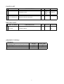
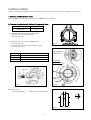
CONROD SET 4B11 I-BEAM NAME OF PRODUCT APPLICATION FORGED CONROD SET (I‐BEAM) MITSUBISHI LANCER EVOLUTION Ⅹ MODEL CZ4A ENGINE 4B11 TURBO PART NUMBER RA111304S1 YEAR REMARKS 2007.10.~ ・This product is a fracture split connecting rod. ・This product was designed for use with the MMC genuine pistons and crankshaft. The RALLIART CONROD SET was developed for racing use and can increase the capacity of the engine power. However, when the engine output is increased, the water temperature and/or the oil temperature will generally increase, and the oil pressure tends to run lower. Always check these conditions in order to maintain optimal engine performance. NOTICE This manual assumes that you have and know how to use the tools and equipment necessary to safely perform service operations on your vehicle. This manual assumes that you are familiar with typical automotive systems and basic service and repair procedures. Do not attempt to carry out the operations shown in this manual unless these assumptions are correct. Always have access to a MMC repair manual. To avoid injury, follow the safety precautions contained in the MMC repair manual. PARTS LIST: E04171-M40030-00 December 25,2009 Ver.3-3.01 PARTS LIST PART NUMBER DESCRIPZTION QTY IMAGE REMARKS 1 CONROD ASSY 4 2 E04171-M40030-00 INSTRUCTIONS MANUAL 1 I-BEAM REPAIR PART PART NUMBER 1 1115A172 DESCRIPZTION CONROD BOLT SPECIFICATIONS CONROD Small End Diameter (mm) Big End Diameter (mm) Hole Center Distance (mm) QTY IMAGE REMARKS 1 Factory φ23 φ55 143.75 1 RALLIART φ23 φ55 143.75 M8 INSTALLATION *Before taking measurements and assembling, make sure all parts are cleaned (including conrod bolts). 1. Removal of MMC genuine Parts Remove MMC genuine parts referring to the MMC service manual. 2. Clearance verification for Big End of Connecting Rods. OIL Clearance (mm) 0.038 ~ 0.069 Limit (mm) 0.100 2.1 Assemble the bearing to conrod big end. Measure the I.D. of the bearing. (See the figure 1.) 2.2 Confirm the O.D. of the crankshaft pin. (See the figure 2.) Or, measure the O.D. of the crankshaft pin. (See the figure 3,4) SIZE NO. 1 2 3 Fig.1 CRANKSHAFT FRONT FIG. PIN DIA. φ51.967~φ51.972 φ51.961~φ51.966 φ51.955~φ51.960 POSITION PIN DIA. SIZE Micro Meter Fig.3 Fig.2 OIL Clearance = “I.D. of the Bearing” - “O.D. of the Crankshaft Pin” Fig.4 2 3. Installation of Connecting Rods 3.1 Install conrods referring to the MMC service manual. 3.2 The projection on the conrod cap faces the “FRONT (Timing Chain Side)” in figure 5. 3.3 Assemble the bearings to the conrod big end. Apply engine oil to the bearings. When installing, do not let the conrod rest against the cylinder wall. 3.4 Apply engine oil on the threads and flange surface of the bolts. Projection Fig.5 3.5 Tighten the conrod bolts in the following order. Equally tighten at 5Nm (0.5kgfm) of torque. Equally tighten at 20Nm (2kgfm) of torque. Starting from “0”, equally tighten to a 90°angle. (See the figure 6) *CAUTION If the tightening angle is less than 90°, the final torque value will not be properly reached. Replace the conrod bolt with a new bolt if it exceeds the values when the bolt is checked according to step 4. If this happens, loosen the bolts and start over from step 3.5. Fig.6 3.6 Measure the thrust clearance with a thickness gauge. (See the figure 7) Thickness Gauge Thrust Clearance (mm) 0.10~0.25 Limit (mm) 0.40 Fig.7 3 4. Check of Conrod bolts. Check the conrod bolt if the tightening angle is exceeded in step 3.5, or if a conrod bolt is reused. Replace the conrod bolt with a new bolt if it exceeds the limit values. Limit (mm) 0.1 4.1 Measure the O.D. of the thickest part (A) of the bolt as shown in figure 8. Fig.8 4.2 Measure the O.D. of the thinnest part (B) within range (X) of the bolt as shown in figure 8. 4.3 Replace the conrod bolt with a new bolt if the difference of the O.D. exceeds the limit value of 0.1mm. *CAUTION Do not use a conrod bolt that exceeds the limit value. Doing so may cause the conrod bolt to break and cause damage to the engine. Confirmation after Installation Check the following after the installation process is complete. (1)Check the following before starting the engine: Make sure all pipes and hoses are routed and connected correctly. Make sure hoses are not twisted or kinked. Make sure the negative cable terminal is securely attached to the battery. Make sure the engine oil level is between H (F) – L. Make sure all bolts and nuts are securely tightened. Make sure all installed components do not come in contact with any other parts. (2)Start the engine and check the following: *Do not raise the engine RPM until the engine reaches its normal operating temperature. (Let it idle.) Make sure oil is not leaking. Make sure there are no vacuum leaks. Make sure fuel, oil, coolant, and air (vacuum) are not leaking after revving the engine 2-3 times while in neutral. Make sure all installed components do not come in contact with any other parts. Make sure the engine oil level is between H (F) – L. 4