1
||||1|m||||| 1 nm 1111015111115!11111011 |||||||||||||| 11
United States Patent [19]
Hoffman et al.
[54]
[11]
Patent Number:
[451
Date of Patent:
COMPUTERIZED DIAGNOSTIC AND
WO89/12279 12/1989
WtPO .
MONITORING SYSTEM
WO92/04693
WIPO .
[75] Inventors: John P. Holfman, Peoria; Ricky D.
Vance, Washington; Dennis A- Bam‘eyi
Morton; J?seph G- Kozlevcar, P9999,
an of I11_
_
3/1992
5,453,939
Sep. 26, 1995
OTHER PUBLICATIONS
Caterpillar Service Manual — “Computerized Monitoring
System With LCD Bargraph Gauges”, published in 1991.
Journal Article — “Microelectronics takes to the road in a
big way: a special report”, pp. 113-122 in the Nov. 20, 1980
_
[73] Assignee: Caterpillar Inc., Peona, Ill.
edition of Electronics
Journal Article — “Expert-systems applied to earth-moving
[21] Appl. No.: 945,451
_
vehicle transmission troubleshooting”, pp. 3840, published
_
[22] med‘
in the Dec., 1990 edition of Automotive Engineer.
Sep' 16,1992
Publication entitled “Introducing the Vital Signs Monitor
[51]
Int. Cl.“ ............................. .. G06F 11/00; B60Q 1/00
p111S Load Weighing System”, by Marathon LeTrouneau,
[52]
US. Cl. .............................. .. 364/551.01; 364/424.03;
Pubhshed 9“ or ab0ut1988-
[58]
73/1172; 340/433; 340/439; 340/461
Field of Search ....................... .. 364/55101, 424.01,
Journal Article — “all on board with O & K” behved to have
been Published on 0‘ abm“ Jan-t 199°, and Sales literature
364/424.03, 424.04; 73/116, 117.2, 117.3;
attaFhed there“)-
340/438, 439, 461, 945, 959
[56]
.. .... .
_
' _
_
Al’tlCl6 from Ropec II‘ldUS'tl'l?S, 1116., re “MlCtOlOgllC, trn
Model SW100, which is a Vehicle Management System”.
References Clted
U‘S_ PATENT DOCUMENTS
Utter
_
Primary Examiner—Emanuel T. Voeltz
Assistant Examiner—M. Kemper
Attorney, Agent, or Finn-Thomas J. Bluth; Steven R. Janda
3,509,529
4/1970
3,516,063
6/1970 Arkin et a1. ....... ..
. . . . ..
340/52
3,866,166
2/1975 Kerscher, HI et a1. ..
340/52
3,393,103 7/1975 McBride, In et a1 __
3,906,437 9/1975 Brandwein et a1. .
4,053,868 10/1977 COX 9t 31- ---------- “
4,072,925 2/1978 Yashlma 6‘ a1‘
340/420
340/27
340/52
340/52
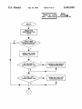
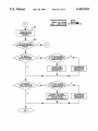
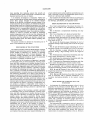
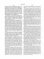
Systems for monitoring sensed parameters and diagnosing
fault conditions are useful in many applications. Advanta
geously, such systems are capable of operating in a plurality
of operating modes and in connection with each of a
340/163
[57]
ABSTRACT
'
4’128’005 12/1978 Amston et a1- '
73/111743
plurality of machines. In the subject invention, a plurality of
4’197’650
4,223,302
4 271 402
4/1980 Bade?’ et a1‘
9/1980 Hocking ........ ..
6,1981 Kasmm et al
33/ 3
340/525
340/52
gauges are included for indicating the levels of the sensed
.
.
.
.
parameters. A plurality of symbols are included for identi
4,376,298
4,442,424
Simon et
3/1933 Sokol et al
4/1984 Shimsaki et a1,
364/551
,,,, __ 340/52
sensed parameters. A Control reC€iV€S an identi?cation
code and selectively illuminates one or more of a plurality
of gauges and symbols in response to the identi?cation code.
4,497,057
1/1985 Kato et a1. .... ..
. 371/29
A plurality of warning lights are each associated with a
4,521,885 6/1985 Melocik 6'1 a1---- -- 371/29
4,551,801 11/1985 Sokol ................ ..
364/424
4,583,176 4/1986 YEIHBIO et a1. .................. .. 364/431.“
switch-type input. A display selectively indicates a pin code
for each switch_type input having a fault condition The
indicator lights having an associated switch_type input in the
(List Continued on next page_)
fault condition are ?ashed. A device selectively indicates a
pin code in response to each diagnosable input having a
present or a previous fault condition.
FOREIGN PATENT DOCUMENTS
3837592A1
5/1990
60-107109 of 1985
Germany .
Japan .
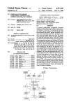
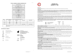
2 Claims, 17 Drawing Sheets
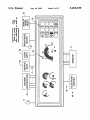
/ so
‘7
MACHINE
42 \. IDENTIFICATION
/ 52
SERVICE
CLEAR
BFtlGHTNESS
[?sh/é‘!
mpur
INPUT
SWITCH
SELECT
Ill-"l “I
34 “°
38
I
31: art
jl/
\
/V
(é‘étt tn}
34th.. @m?
El [El
ms 4F
/\
43 ->
46->
E?bmg?c
I
'3'"
— — —
SENSORS
’ 11
new
mm
mm
~11
5,453,939
Page 2
US. PATENT DOCUMENTS
4,667,176
5/1987
4,694,408
9,1987 Zaleski ____ u
4,975,848
12/1990 Abe 61:11. ........................ .. 364/42403
4’977’389
12/1990
364,551
5,019,799
5/1991
Matsuda .................................. .. 340/52
shufnshl
'''‘‘
' ' ' " 340/461
Osh1age (it al. ....................... .. 340/438
4,748,843
6/1938 schafer et a1_
____ __ 73/1173
5,034,889
7/1991 Abe .................................. .. 364/424.04
4,809,177
4,811,240
2/1989 Windle 6t a1. ................... .. 364/424.01
3/1989 B31101! 6131. ................ .. 364/424.01 X
5,041,980
5,050,080
8/1991 Maddock er a1. ................ .. 364/43103
9/1991 Abe .................................. .. 364/424.04
4,812,744
3/1989
4,815,824
3/1989 Shawl“
Havel
. . . . . .. .
. . . . . ..
324/115
5,091,858
2/1992
350/336
5,150,609
9/1992 Ebner BI a1. ......................... .. 73/1173
4’843’557
6/1989 Ina etal
4,862,395
8/1989 Fey e161.
4,896,276
1/1990
..... .. 364/550
4,926,331
5/1990 Windle B131.
Paielli
364'431'77
5,157,610
10/1992 Asano et a1. ..................... .. 364/424.03
..... .. 364/561
5214 582
5,1993 Gm
364,431.12
364,424 03
-
4,939,652
4,967,143
Saglimbeni 61 a1.
3
Y ------ -
5,257,190 19/1993 Crane ~
364424-03
364/42404
5,313,388
5/1994 Cortis -------- -
364/424-04
10/1990 Raviglione et a1. ................. .. 324/731
5,327,344
7/1994 Hoffman et a1- ................. -- 364/424.03
7/1990
Steiner ............ ..
.. 364/42404
3
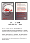
US. Patent
Sep. 26, 1995
Sheet 1 0f 17
5,453,939
[I
I]
QB I]
U
@U
U I]
EEIU
FI
/
3634 /
§“%8
g/E'miCI)
<1: 38
3 ‘I2
9CRBB3E0D3c/anVI GEE
B
8
35%!
6§
r/
k\ 2
/
30 /
a 33
US. Patent
Sep. 26, 1995
Sheet 2 0f 17
/////z’
5,453,939
U.S. Patent
Sep. 26, 1995
Sheet 4 of 17
5,453,939
US. Patent
Sep. 26, 1995
r_H_
(Em.
Sheet 5 of 17
m.E
Emu
5,453,939
PCmmv
s
a
8\“_r
B
_H_
5%(/8Q
K
x
mm
US. Patent
Sep. 26, 1995
Sheet 6 of 17
[I]
‘5
E
[II-CHE]
aw Um @w
mm
mm
5,453,939
US. Patent
Sep. 26, 1995
5,453,939
Sheet 7 of 17
m5
m
{X
(w
gmm.
5/
mglwsCum
?aw
(AVQ
QEé/t/\muma‘
\
/
US. Patent
Sep. 26, 1995
Sheet 8 of 17
5,453,939
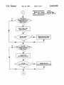
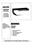
FLEJEIE
READ THE
IDENTIFICATION
CODE
ARE TURN
SIGNALS USED ON
THIS VEHICLE?
READ THE TURN
SIGNAL INPUTS
V
IS THE RIGHT
RN
TURN SIGNAL ON?
N THE RIGHT
Tl?l'uRNolNDlcATOR
4
I
IS THE LEFT
TURN SIGNAL ON‘?
L
‘
.
I
US. Patent
Sep. 26, 1995
Sheet 9 of 17
5,453,939
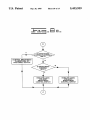
PLE_EI:I_
IS
THE HIGH
BEAM INDICATOR
USED ON THIS
MACHINE?
READ THE HIGH ‘
BEAM INPUT
IS THE HIGH
BEAM ON?
TURN ON THE HIGH
BEAM INDICATOR
I
IS THE
' ETARDER INDICATOR
USED ON THIS
ACHINE
READ THE
RETARDER INPUT
IS THE
RETARDER ON‘?
TURN ON THE
RETARDER INDICATOR
‘
I
US. Patent
Sep. 26, 1995
Sheet 10 0f 17
5,453,939
$112.15 |:_
IS BRIGHTNESS
CONTROL PHOTOCELL
ONLY?
CONTROL BRIGHTNESS
IN RESPONSE TO
PHOTOCELL OUTPUT
IS BRIGHTNESS
'
CONTROL
SPST?
Y
EXECUTE LOGIC
FOR SPST
BRIGHTNESS
CONTROL SWITCH
EXECUTE LOGIC
FOR SPDT
BRIGHTNESS
CONTROL SWITCH
US. Patent
Sep. 26, 1995
Sheet 11 0f 17
5,453,939
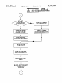
FLEJEIEI.
IS THIS A
LOW WARNING
STYLE GAUGE ?
TURN ON LOWER
GAUGE OUTLINE
I
TURN ON UPPER
GAUGE OUTLINE
I
ENABLE UPPER
WARNING SEGMENTS
I
I
READ GAUGE
DATA
I
MAP GAUGE DATA
TO SEGMENT DATA
I
READ SINGLE/FILL
INPUT
I
BUILD AND TRANSMIT
SENSOR DATA
MESSAGE
ENABLE LOWER
WARNING SEGMENTS
US. Patent
Sep. 26, 1995
@
Sheet 12 of 17
5,453,939
:::.I__:-_EIE_
#I
550
TURN ON THE
APPROPRIATE
SYMBOL
IS THE GAUGE
IN SINGLE SEGMENT
MODE’?
IS THIS A
LOW WARNING
STYLE GAUGE?
IS THE GAUGE
IN A LOW WARNING
CONDITION?
FLASH THE
LOW WARNING
SEGMENTS
I
IS THIS A
HIGH WARNING)
STYLE GAUGE-
ILLUMINATE
INDICATING
SEGMENTS
4
N
IN IISIIQEI
(IIv'ZUFICi?NG
CONDITION?
Y
1
FLASH THE HIGH
ILLUMINATE
WARNING SEGMENTS
AND ALL THE
INDICATING SEGMENTS
INDICATING
SEGMENTS
I
1
US. Patent
Sep. 26, 1995
Sheet 13 of 17
5,453,939
..:"_T.. E
IS THIS A
LOW WARNING
IS THE GAUGE
IN A LOW WARNING
STYLE GAUGE?
CONDITION?
FLASH A
LDW WARNING
SEGMENT
ILLUMINATE A
SINGLE INDICATING
SEGMENT
I
IS THIS A
HIGH WARNING
STYLE GAUGE?
IS THE GAUGE
IN A HIGH WARNING
CONDITION?
FLASH A
HIGH WARNING
SEGMENT
I
ILLUMINATE A
SINGLE INDICATING
SEGMENT
US. Patent
Sep. 26, 1995
5,453,939
Sheet 14 0f 17
4-1.5 -EE
READ THE HARNESS
IDENTIFICATION
CODE
I
READ ALL
INPUTS
I
PERFORM SYSTEM
DIAGNOSTICS
IS THE SYSTEM
IN SERVICE MODE ‘.7
DISPLAY FAULT
CODES AND STATUS
IS SERVICE
INPUT GROUNDED ?
DISPLAY NEXT
FAULT CODE AND
STATUS
SOUND THE
ALARM FOR
0.5 SECONDS
I
DISPLAY INPUT
PIN NUMBER
US. Patent
Sep. 26, 1995
HAVE ANY
Sheet 15 0f 17
Y
DISPLAY THE INPUT
olHAilij?Tlgpéil?seAg
PIN # FOR ALL CHANGED
TATUS?
>
FAULT CONDITIONS
1
IS THE SYSTEM
IN STATUS MODE ?
FLASH ALL INDICATOR
LIGHTS CORRESPONDING
TO INPUTS THAT ARE
NOT GROUNDED
I
DISPLAY PIN # FOR ALL
SWITCH INPUTS THAT
ARE NOT GROUNDED
I
STEADILY ILLUMINATE
INDICATOR LIGHT
CORRESPONDING TO
DISPLAYED PIN #
SOUND HORN FOR
0.5 SECOND
I
DISPLAY INPUT # FOR
SWITCH INPUTS THAT
CHANGED STATUS
5,453,939
‘
US. Patent
Sep. 26, 1995
Sheet 16 of 17
5,453,939
FLE__I_[:IE_
IN NUMEFIlC
Baggy
N
RESET
TIMER
SET PARAMETER
NUMBER TO ZERO
SCROLL
ACTIVE?
TIMER
EXPIRED?
INCREM ENT
PARAMETER #
N
V
RESET
TIMER
'N
DISPLAY CURRENT
PARAMETER #
I
DISPLAY CURRENT
PARAMETER DATA
US. Patent
Sep. 26, 1995
Sheet 17 of 17
5,453,939
Flaulljh;
IS THIS A
GAUGE
PAHAM ETER?
IS THE
PARAMETER
ENGINE SPD?
IS THE
PARAMETER
VEHICLE SPD?
NK THE
GAUGE OUTLINE
__>_._
TURN ON THE
RPM ISO SYMBOL
F
+
Y
IS THE SPD
INUAIGIFJSQC
TURN ON THE
l'KMH" ISO SYMBOL
‘ @D
T
TURN ON THE
"MPH" ISO SYMBOL
_>__
5,453,939
1
2
COIVIPUTERIZED DIAGNOSTIC AND
MONITORING SYSTEM
particularly large off-highway work vehicles, are becoming
increasingly complex in their design thus making it more
TECHNICAL FIELD
and more di?icult for service personnel to locate defects in
machine sensors and systems. This is particularly true of
intermittent defects not resulting in a breakdown of a system
or the vehicle but which interfere with its operation.
The invention relates generally to a computerized moni
toring and diagnostic system, and more particularly, to a
A major frustration when troubleshooting electrical prob
monitoring and diagnostic system having a plurality of
operating modes.
lems on a large work vehicle is caused by intermittent
10
BACKGROUND ART
problems. Typically, the operator reports some symptom to
a technician and before the technician can get to the machine
the problem is no longer present.
If the condition is not present it is helpful for the techni
In a variety of engine-powered vehicles, monitoring and
diagnostic devices are employed to detect the presence of
various undesirable operating conditions, such as overheat
ing of the engine, low oil pressure, low fuel, and the like, and
cian to re-create the fault condition. In many cases the fault
condition is caused by a short to ground potential or an open
circuit. To recreate these fault conditions, the technician
manipulates the wire harnesses or wire connectors to deter
indicators are provided to warn the operator of such condi
tions. These instruments are typically connected to various
tions on the vehicle via a wire harness and/or a communi
mine the point at which the fault has occurred.
Prior art systems have indicated when fault conditions are
present. In connection with such systems, the technician
cation link. In many applications, these instruments are also
connected to electronic control systems, for example elec
tion is present. In troubleshooting intermittent problems
sensors and switches for monitoring or controlling condi
must view a visual display to determine whether the condi
tronic engine controls, electronic transmission controls, and
when the fault condition is not currently present, the tech
the like.
nician must manipulate wire harnesses and connectors to
Most prior art systems have included dedicated instru 25 recreate the fault and thus cause the fault indication to be
displayed. When the fault condition is present, the techni
ments in which the functions and conditions of the vehicle
cian must manipulate wire harnesses and connectors and
to be monitored or diagnosed, as well as the particular
observe whether the manipulations eliminate the fault and
sensors provided on the vehicle, are identi?ed in advance.
thus cause the fault indication to disappear.
Therefore, the instruments are speci?cally designed for and
hence “dedicated” to the monitoring or diagnosing of those 30
In many cases, however, the machine is of su?icient size
particular vehicle functions and conditions in response to
that the technician must leave the area of the diagnostic tool
signals from pre-identi?ed sensors. Accordingly, such “dedi~
to recreate the fault condition. Therefore, any visual indi
cated” instruments generally cannot be readily modi?ed to
cator provided by the diagnostic tool is not visible to the
technician. To effectively troubleshoot the electrical system
accommodate different machines, different sensors and/or
different conditions and functions. Rather, such instruments
on such a large machine, typically two or more technicians
are generally limited to use with a particular vehicle type or
are required and repair expenses are thus greatly increased.
Similarly, the vehicle may not be repairable immediately if
only a single technician is available.
In addition, these machines typically include switch-type
inputs that are either in an open voltage or grounded
model for which the instrument has been designed.
However, it is advantageous for these instruments to be
usable in connection with many different machines. Lower
costs are achieved and less warehousing space is required if
a single instrument can be manufactured which can be used
condition. One of the voltage conditions is de?ned as a fault
condition. In most cases, the fault condition is de?ned as the
in many different applications. Similarly, service time is
reduced if software changes are avoided when an instrument
is moved from one machine to another.
Some prior art systems have provided for standardized
open voltage condition thus whenever the wire between the
45
sensor and the display is severed or disconnected, a fault
condition is indicated. Similarly, if the switch-type input is
monitoring systems that are usable in connection with a
connected to a switch-type sensor, the switch-type sensor
variety of machines, for example the system shown in US.
disconnects the sensor output from ground potential when
Pat. No. 4,551,801 issued to Sokol on Nov. 5, 1985. While
the sensed parameter exceeds a warning level.
being an improvement over dedicated systems, this moni
toring system is still relatively in?exible and requires the
for each switch-type sensor that is in a fault condition. Each
Some prior art systems have illuminated a warning light
addition or subtraction of monitoring modules and the use of
warning light is associated with one of the switch-type
sensors and is illuminated when the display input associated
with that switch-type sensor is indicating a fault condition.
decals to indicate the parameters being shown by each
display module.
One area of desired ?exibility is for each gauge in the
instrument to be capable of indicating parameters having a
55
advantageous to also indicate the pin number of the input
associated with the switch-type sensor. Optimally, the tech
nician should be able to determine the pin number of each
of the warning lights indicating a fault condition even
though there are more than one of such warning lights. This
would allow technicians to more readily identify the fault
condition and associate the sensor having the fault condition
high warning level, for example engine temperature, and
also parameters having a low warning level, for example
brake ?uid pressure. Prior art systems required the use of
decals to indicate that the gauge was indicating the level of
a parameter having either a high or low warning level and/or
the use of a separate warning light to show that the param
eter was outside the normal operating range.
To maximize system ?exibility, it is advantageous for the
instrument to be capable of performing a number of diag
nostic functions in addition to displaying parameter values
and indicating warning conditions. Today’s machines, and
While adequate for many purposes, in other cases it is
to the relevant connector pin.
While troubleshooting some diagnosable sensor prob
65
lems, it is sometimes di?icult to determine whether a sensor
is producing a signal that is truly representative of the actual
level of the sensed parameter. This often results in techni