1
United States Patent [19]
[11] Patent Number:
Pitchford et al. _
[45]
[54] PERSONAL MULTI-PURPOSE
NAVIGATIONAL APPARATUS AND
Date of Patent:
4,977,509
Dec. 11, 1990
FOREIGN PATENT DOCUMENTS
METHOD FOR OPERATION THEREOF
2711343
9/1978 Fed. Rep. of Germany ...... .. 73/384
2382728 11/1978
[75] Inventors: Gary Pitchford, Phoenix; Steve
France .............................. .. 364/443
Primary Examiner-Parshotam S. Lall
Pitchford, Mesa, both of Ariz.; Paul
Hyde, Pleasant Hills, Calif.
Assistant Examiner—Michael Zanelli
[21] Appl. No.: 357,843
Attorney, Agent, or Firm-Armstrong, Nikaido,
Marmelstein, Kubovcik & Murray
[57]
ABSTRACT
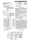
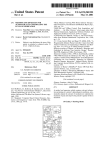
A personal multi-purpose navigational instrument
[22] Filed:
long distances is disclosed. The navigational instrument
[73] Assignee: Campsport, Inc., Phoenix, Ariz.
which can be hand held and portable for transporting at
May 30, 1989
can receive, process, display, store and interface data
for navigational use, such as, bearing information, incli
nation and declination,temperature, barometric pres
sure, current and elapse times, or the like. The naviga
tional instrument has an internal ?ux gate magnetome
Related U.S. Application Data
[63]
Continuation-in-part of Ser. No. 281,734, Dec. 9, 1988,
abandoned.
[51]
[52]
Int. Cl.5 ............................................ .. G06F 15/50
ter, solid state temperature sensor, solid state baromet
ric pressure sensor, infrared sensor, and real time clock.
U.S. Cl. .................................. .. 364/449; 364/443;
The navigational instrument has a foldable LCD display
[53]
Field of Search ............. .. 364/420, 443, 444, 448,
for outputting the desired navigational information and
364/457; 364/557; 364/558; 364/705.01
a keyboard for instructing or inputting information
through an internal microprocessor. Numerous func‘
364/449, 453, 458, 460, 557, 558, 559, 569,
570-57108, 709.01, 709.02, 709.11, 709.12,
710.02, 715.07, 721, 705.01, 710.07, 710.14;
235/61 NV; 73/178, 386, 384; 324/433, 244,
252; 250/3381, 338.4, 342; 374/109, 121
[56]
tions can be performed as desired by way of the opera
tions performed by the user on the keyboard; i.e., by
way of speci?cally operating the multiple keys or but
tons on the keyboard in various speci?c steps in order to
achieve, for display or the like, the desired navigational
information. A protractor/graduated scale and a pop
up lens extend from the navigational instrument for use
in orienteering, mapping or course plotting. An infrared
References Cited
U.S. PATENT DOCUMENTS
3,924,111 12/1975
4,317,106
2/1982
Hiiber
4,445,090
4/ 1984
Melocik et al. . . . . .
4,636,093
l/l987 Nagasaka et a1.
. ... .. ... .. ..
. . . ..
364/557
364/449
9/1987
Vlakancie et al. .
..... .. 73/386
l/l989
Fraden
. . . ..
... . . ... .. ..
4,831,538 5/1989 Cucchiari
364/557
364/443
. ... .
. . . ..
4,874,253 10/1989 Pompei et al
4,878,170 10/1989
internal CPU of the instrument and another electronic
device, computer or the like, is also provided. The inter
nal components are effectively arranged between upper
and lower casings to provide a very compact and porta
ble navigational instrument which can withstand the
. . . .. 324/433
4,797,840
Lanchais
put/output port for serially interfacing between the
364/444
4,694,694
8/1989
detecting the presence of “hot” bodies. An optical in
364/443
4,642,776 2/ 1987 Matsumoto et al.
4,857,840
sensor is provided for use at dark environments for
Farris ................................ .. 364/443
4,172,285 10/1979 Yoshida et a1. .
worst or weather conditions.
364/460
374/121
37 Claims, 7 Drawing Sheets
Zeevi ................................. .. 364/444
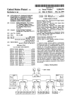
70
5
FL UX GA TE
MAG METER
BATTERY
28
TEMP
SENSOR
68
30
HARM
SENSOR
SENSOH
BATTERY
22
SERIAL
CENTRAL
INTERFACE
PROCESS/N6
UNIT
KEYBD
INTERFACE
92
FREEZ
HITTON
20
TEMPE/PA TURE
SENS! TI VEI
DISPLAY '__ DISPLA
Y CONTRAST
KEYEOA RD
5
r
US. Patent
Dec. 11,1990
F/GZ
Sheet 1 of 7
4,977,509
US. Patent ,
Dec. 11, 1990
Sheet 2 of 7
/4
~ IGN,
______.
4,977,509
US. Patent
Dec. 11, 1990
Sheet 3 of 7
4,977,509
US. Patent
’
Dec. 11,1990 I
FLUX GATE
MAG‘ METER
Sheet 5 017
/70
/5
BA TTERY
BA TTERY
(28
TEMP
SENSOR
(as
(30
BARM
SENSOR
IFR
SENSOR
ANALOG MUX
90
/
4,977,509
84
‘r.
g
V/F CONVERTER
Q,
p
a0
E:
k
%
E
/ 88
/
CENTRAL
PRO Cass/N6
UNIT
KEYBD /92.
SERIAL
//v TERI-‘ACE
FREEZE
INTERFACE
BUTTON
20
TEMPERA TURE
DISPLA Y '
sE/vs/ T/ vE:
DISPLA Y CONTRAST
KEYBOA R0 1
Z5
F167
US. Patent
Dec. 11, 1990
Sheet 6 of 7
4,977,509
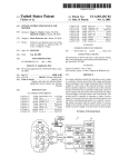
REAL TIME CLOCK INTERRUPTHANDLER
F/ 6 90
UPDATE CLOCK COUNTERS
INCREMENT SLA VE COUNTERS
FOR ALL OTl-{ER PROCESSES
RET'uRN
KEYBOARD /N TERRUR T HANDLER
I
READ, KEY ll/ALUE IN
SET REsPEc'T/vE KEY BIT
FOR TASK NANAOER
RET'uRN
D/SPLAY MANAGER
120 ~cHEcK FOR D/SPLAY TIME ExcEEDED - -NO -LOOP —]
.
1
YES
|
/22~LOAD DISPLAY BUIFFER POINTER
|
|
l24~ /NcREMENT D/SPLIA Y BUFFER PO/N TER
l26- SAVE NEw DISPLAY BUFFER PO/NTER
|
l
I
|
/2a \. LOAD D/SPLA Y BUIFFER T0 D/SPLA Y
130
RET'uRN-—- —-
FIG‘. IO
— - — —
|
—
—
—
—
—
1
4,977,509
2
cial operations to provide numerous navigational infor
PERSONAL MULTI-PURPOSE NAVIGATIONAL
APPARATUS AND METHOD FOR OPERATION
THEREOF
mation desired by the user.
It is a further object of this invention to provide a
This application is a continuation-in-part of applica
device, an externally located computer, or the like to
personal multi-purpose navigational instrument having
an input/output port for allowing an external electronic
tion Ser. No. 281,734 ?led Dec. 9, 1988 now abandoned.
communicate with the navigational instrument.
BACKGROUND OF THE INVENTION
This invention generally relates to a personal multi
purpose navigational apparatus for use generally in
numerous activities. More particularly, the invention
multi-purpose navigational instrument preferably hav
It is a further object of the this invention to provide a
ing an automatic or user-defmable liquid crystal display
contrast function which is dependent on measured sur
rounding or internal temperature.
It is a further object of the this invention to provide a
relates to a personal multi-purpose navigational device
having the capabilities of providing numerous naviga
multi-purpose navigational instrument having a lighting
tional information, including direction, orientation,
mechanism for night use which may be set to automati
barometric pressure, temperature, current and elapse
cally engage when the user activates the navigational
instrument for speci?c period of time during the day or
a lighting mechanism which can be manually engaged.
times, angles, distances, estimated time of arrival, alti
tude, inclination, declination, general weather condi
tions, location of “hot” bodies, or the like.
Often, a compact and portable device is essential in
providing required or important information for use in
industry, military, or the like. In most instances, a navi
It is a further object of this invention to provide an
infrared thermal scan suitable for locating thermal or
“hot” bodies within surrounding areas.
It is yet another object of this invention to provide a
combination of all the above features within a compact,
gational instrument capable of providing a plurality of
portable and sturdy personal multi-purpose naviga
information is essential in order to avoid experiencing
any problems in these activities and, in most instances, a
tional apparatus.
navigational instrument is essential in obtaining the
In accordance with one embodiment of this inven
activities’ goals. Moreover, the use of a compact and
tion, a personal multi-purpose navigational instrument
portable navigational instrument capable of providing a
for use in a multitude of activities is disclosed. In this
embodiment, a multipurpose keyboard which commu
multitude of essential information enhances the user’s
involvement in these activities.
Accordingly, there is a need for a personal multi-pur
pose navigational apparatus or instrument which is
nicates with an internal microprocessor allows the user
to communicate with the instrument for providing any
desired navigational information. The instrument in
portable, compact, lightweight, durable and capable of
cludes the immediate display of navigational informa
tion in digital form and digital bearing read-out from a
other information on the user’s environment. Such a 35 ?ux gate sensor within the instrument. Determination of
personal multi-purpose navigational instrument should
a corresponding course heading and the storage of the
providing a multitude of navigational information and
have suf?cient rigidity and durability capable of being
corresponding bearing, can be performed in the naviga
used in the worst environmental conditions of different
tional instrument of the instant invention. The naviga
tional instrument is provided with top and bottom cas
types of activities, such as, sailing, Orienteering, back
packing, ?shing, forestry, surveying, geology, infantry,
40
survival and rescue activities, or the like. Moreover, the
ings for mounting thereon an LCD display for reading
therefrom the navigational information. The naviga
personal multi-purpose navigational instrument should
tional instrument preferably has an automatic or user
be made of lightweight materials so as to be easily car
de?nable liquid crystal display contrast function which
ried at long distances and at rugged terrain. The per
sonal multi-purpose navigational instrument should
is dependent on measured surrounding or internal tem
45
further be well suited for communicating with external
perature. Furthermore, the navigational instrument has
electronic instruments in order to more fully serve the
a lighting mechanism for night use which may be set to
automatically engage when the user activates the navi
user.
gational instrument for speci?c period of time during
the day or a lighting mechanism which can be manually
SUMMARY OF THE INVENTION
It is an object of this invention to provide a personal
engaged. Moreover, a keyboard is operably mounted
onto the top casing in order for the user to conveniently
communicate with the microprocessor therein. Numer
ous functions can be performed as desired by way of the
multi-purpose navigational apparatus and method of
operation thereof.
'
It is another object of this invention to provide a
personal multi-purpose navigational instrument which
can be instructed to output temperature and barometric
pressure.
It is another object of this invention to provide a
personal multi-purpose navigational instrument capable
of being operated by battery and utilizing special low
power consumption circuitry for extending the opera
tional life and providing long term data storage in the
instrument’s memory.
It is another object of this invention to accomplish the
above by a personal multi-purpose navigational instru
ment having a multi-function keyboard for allowing a
user to interact or communicate with the navigational
instrument by, for example, selecting a number of spe
55
operations performed by the user on the keyboard; i.e.,
by way of speci?cally operating the multiple keys or
buttons on the keyboard in various speci?c steps in
order to achieve, for display or the like, the desired
navigational information. A freeze switch is operably
mounted within the casings for allowing any informa
tion outputted on the LCD display to beheld for conve
nient and easy reading by the user. A pop-up lens is
incorporated within the front portion of the instrument
for allowing the user to simultaneously observe a target
sight and navigational information displayed on the
LCD display. A scaled protractor having fold-down
capabilities is further operationally integrated within
the body of the instrument for providing essential infor
mation with a map during navigation. An input/output
3
4,977,509
port portion is further provided on a side portion of the
instrument for allowing another microprocessor or an
external electronic instrument to be operably connected
to the internal microprocessor for allowing the internal
microprocessor to communicate with the external mi
protractor and graduated scale 3 is also preferably in the
form of clear plastic plate etched with a protractor and
croprocessor or the external electronic instrument. A
?ux gate, barometric sensor, temperature sensor and
infrared sensor are all incorporated within the instru
graduated scale 3 for map use, or the like. The LCD
display 5 is also preferably one which can be folded up
ment and operably integrated within the internal micro
or down (see, FIGS. 3 and 6). The LCD display 5 is
used for displaying information desired by a user (such
as, barometric pressure, temperature, bearings, inclina
tion/declination, current time, elapse time, or the like).
processor.
The foregoing and other objects, features and advan
tages of this invention will be apparent from the follow
ing, more particular, description of the preferred em
bodiments of this invention, as illustrated in the accom
panying drawings.
The keyboard 7 allows a user to input or output any of
the above-described information in a manner which will
15 later be more fully discussed. The pop-up lens 9 is more
fully shown in FIGS. 2-4.
BRIEF DESCRIPTION OF THE DRAWINGS
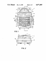
FIG. 1 is a top view of the fully assembled personal
In FIG. 2, it can be seen that the pop-up lens 9 in its
upstanding position allows a user to sight an object and
multi-purpose navigational instrument in accordance
with the present invention showing the protractor scale,
LCD display, keyboard and pop-up lens;
simultaneously read the bearing information from the
LCD display 5, either at daytime or at night time. In
line with the pop-up lens 9, is a forward sight portion 11
preferably integral to the top portion of the LCD dis
play 5.
FIG. .2 is an elevational view showing a rear end
portion of the personal multi-purpose navigational in
strument of the instant invention showing the LCD
display in its upstanding position;
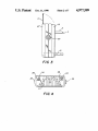
FIG. 3 is a left side elevational view of the personal
multi-purpose navigational instrument of the instant
invention showing the freeze switch, extending side
portion of the protracted scale, upstanding side portion
of the LCD display, and the upstanding position of the
pop-up lens;
FIG. 4 is a front end elevational view of the naviga
tional instrument showing a folded up protractor and
graduated scale.
4
display 5, a keyboard 7, and a pop-up lens 9. The pro
tractor and graduated scale 3 is one which can prefera
bly be folded up or down (see, e.g., FIG. 3) and is pref
erably made of clear plastic material or the like. The
As can be seen in FIG. 2, the navigational instrument
25
1 is enclosed by upper 14 and lower 16 casings. Located
at the bottom rear end portion of the lower casings 16
are battery doors 18. It is preferable that the upper 14
and lower 16 casings are made of sturdy and long-last
ing materials and are ?tted together so as to allow the
navigational instrument 1 to be used in the most hostile
environment (e.g., constant vibrations due to rugged
terrain, water resistant due to weather conditions, ex
treme hot and cold weather conditions, or the like). On
one side of the navigational instrument 1 is a freeze
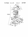
FIG. Sis a perspective exploded view of the personal
switch 20 which permits a user to hold or freeze any
multi-purpose navigational instrument of the instant
invention;
information displayed on the LCD display 5; thereby
allowing the information to be conveniently and readily
FIG. 6 is a cross-sectional view taken along line 6-6
of FIG. 1 showing the manner in which the internal
instrument 1, is an input/output port 22 for allowing
components of the personal multi-purpose navigational
read by the user. Also at one side of the navigational
40 another instrument (such as, an external electronic in
instrument of the instant invention is effectively and
compactly arranged within the upper and lower cas
11185;
strument, microprocessor, or the like) to communicate
with an internal microprocessor, later to be discussed,
of the navigational instrument 1, or vice versa.
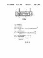
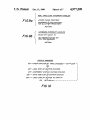
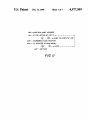
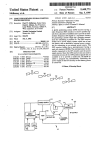
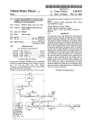
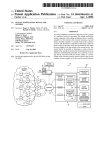
FIG. 7 is a block diagram showing the manner in
Shown in FIG. 3 are the structural and operational
which the different structures of the personal multi-pur 45 relationships of the extended or upstanding protractor
pose navigational instrument of the instant invention are
and graduated scale 3, LCD display 5, and pop-up lens
operably connected to each other;
9.
FIG. 8 is a ?ow chart showing the manner in which
FIG. 4 illustrates the front end view of the naviga
the personal multi-purpose navigational instrument is
tional instrument 1 when the protractor and graduated
operated;
'
scale 3 is folded up for abutting the front end side por
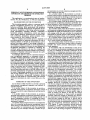
FIG. 9A is a ?ow chart more particularly showing
tion of the navigational instrument 1. The protractor
the manner in which the real time clock interrupt han
and graduated scale 3 preferably has apertures 24, 26
dler is operated, while FIG. 9B is a ?ow chart more
particularly showing the manner in which the keyboard
interrupt handler is operated;
passing therethrough. The apertures 24, 26 are provided
for allowing a temperature sensor 28 and an infrared
55 sensor 30 to outwardly extend from the front end side of
FIG. 10 is a flow chart which more speci?cally illus
trates the manner in which the display manager, shown
the navigational instrument 1.
The exploded view illustrated in FIG. 5 more fully
in FIG. 8, is operated; and
shows the manner in which the above-discussed parts
FIG. 11 is a flow chart more particularly showing the
manner in which the task manager, shown in FIG. 8, is
are arranged, along with other parts yet to be discussed,‘
within the upper 14 and lower 16 casings of the naviga
tional instrument 1. As shown in FIG. 5, the LCD dis
play 5 is preferably hinged to the upper casing 14 for
allowing it to take on upstanding position or a position
operated.
DESCRIPTION OF THE PREFERRED
EMBODIMENTS
which allows it to be accommodated within the elon
FIG. 1 shows the top elevational view of the personal 65 gated indented portion 32 of the upper casing 14. The
multi-purpose navigational instrument (hereinafter,
‘LCD display 5 has connecting wires 34 for connecting
“navigational instrument”), generally designated by
to an internal microprocessor 40. The upper casing 14
reference No. 1, showing a protractor scale 3, an LCD
has an enlarged opening 42 passing therethrough for
5
4,977,509
6
accommodating the keyboard 7 therein. The upper
freeze button 20 is also operably connected to the CPU
casing further has substantially semicircular shaped
passes through the front portion of the upper casing 14
for accommodating therein the pop-up lens 9 during its
88 for momentarily halting or freezing the display of
information on the LCD display 5; thereby, allowing
the displayed information to be conveniently and
readily read by the user.
The operation of the navigational instrument 1 is
hereinafter described. Initially, the instrument 1, by way
upstanding position.
of a software, queries the user for the correct time and
openings 44, 46 for accommodating therein portions of
the freeze switch 20 and the inlet/outlet port 22, respec
tively. A substantially rectangular opening 48 also
As further shown in FIG. 5, the lower casing 16 also
date, and from there, the microprocessor 40 proceeds to
has substantially semicircular shaped openings 50,‘ 52
for accommodating therein portions of the freeze
switch 20 and the input/output port 22, respectively.
maintain the current time through the use of software
and internal counter timers within the CPU. The ana
The lower casing 16 further has an upstanding channel
54 for accommodating therein the pop-up lens 9. The
lower casing 16 further has a back side portion having
stantly monitoring bearing signals, temperature signals,
mounted thereon guide members (such as, guide tubes,
or the like) 58, 60 for mounting thereon the temperature
sensor 28 and the infrared sensor 30, respectively. The
infrared sensor 30 is operably connected to a generator
log-to-digital converter is used by the software for con
pressure signals and power status signals. The data from
the various signals can then be used to calculate various
functions for display until the user requests more spe
ci?c calculations through the use of the keyboard 7.
Examples of speci?c functions performed by the micro
processor 40 include the current barometric pressure
(not shown) which is operably connected to a micro 20 corrected for temperature for providing the density
processor 40 for driving the infrared sensor 30 by way
altitude, or the use of the keyboard 7 as a calculator.
of the microprocessor 40. At the internal base portion
Moreover, the user may specify certain data for reten
62 of the lower casing 16 is a dish-like member 64 hav
tion in the RAM 90 until such time as when the data,
ing a perforated bottom portion 66 passing through the
when desired, is loaded into additional instruments or
base side 62 of the lower casing for accommodating 25 another computer through the use of the software
which provides the communication capability through
thereon a barometric pressure sensor 68. The baromet
ric pressure sensor 68 is preferably one which is of a
the input/output port 22 of the serial interface of the
solid state type.
CPU 88.
A lanyard rod 55 is lodged within a groove portion 57
As illustrated in FIG. 8, when the power is turned on
of the lower casing 16 for allowing a strap (not shown)
(step 101), the CPU 88 proceeds to execute the initial
to be coupled for use when carrying the instrument 1.
ization (step 102) portion of the software. The CPU 88
Immediately beneath the keyboard 7 is a micro
then self-tests (step 103) its internal mechanisms. Exam
ples of the tests performed by the CPU 88 under the
processor 40 having a read only memory (ROM) por
tion for housing the microprocessor software and a
self-tests mode 103 include a test of the memory, battery
random access memory (RAM) for storing data and 35 voltage and real time clock data validity. If all the tests
programs. The microprocessor 40 is preferably an “IN
results in the tested functions are correct, the CPU 88
TEL” 8031 type, or the like. Immediately below the
continues through the main software execution. At this
microprocessor 40 is a flux gate magnetometer 70 in a
point, the sensors 28, 68 are read by the CPU 88 for
circuit board 72 having an X and Y output being on an
establishing initial values and are then loaded into sepa
orthogonal relationship with each other. The flux gate 40 rate buffers in the microprocessor memory. The display
magnetometer 70 provides azimuth information, along
manager (step 109), see also FIG. 10, begins to execute
with other navigational information, which are then
translated and stored for outputting to the LCD display
5 from a user’s instructions through the keyboard 7. The
flux gate magnetometer 70 is preferably that of a solid 45
state device.
The manner in which the above-described compo
nents are connected to each other is illustrated in FIG.
7 and are shown in FIG. 6 to be arranged in a very
compact manner inside the upper 14 and lower 16 cas
and the display data is fed from the internal buffers. The
display manager in step 109 operates through a series of
different types of data (i.e., temperature, magnetic hear
ing, magnetic back bearing, true bearing, true back
bearing, pressure altitude, time or the like) and the dis
play data is continually updated every second. The
actual display data, sequence, and rate are de?nable by
the user.
ings. As illustrated in FIG. 7, the battery 15, for power
supply encased within the battery door 18 is connected
to an analog multiplexer 80. Moreover, the temperature
As indicated in FIGS. 9A and 9B, interrupt driven
processes occur as required. Examples of the interrupt
modes include the operation of the real time clock, and
keyboard processes which are driven by the timer inter
sensor 28, infrared sensor 30, barometric sensor 68, and
rupt steps (see FIG. 9A) and keyboard interrupt step
the flux gate magnetometer 70 are all operably coupled 55 (see FIG. 9B), respectively.
to the analog multiplexer. 80. The analog multiplexer 80
As the microprocessor 40 executes its primary soft
is directly connected to a serial analog-to-digital con
ware in an endless loop (steps 109-111), the micro
verter 84 which is, in turn, operably connected to the
processor 40 awaits for a user to input via the keyboard
central processing (CPU) 88 of the microprocessor 40.
7 for any commands on additional or more speci?c
The CPU 88 preferably has a random access memory
functions. Examples of additional or more speci?c func
(RAM) 90. Also, the CPU 88 preferably has a read only
tions include, for example, with the use of the keyboard
memory (ROM), timers, serial unit, and master oscilla
7, navigational calculations, bearing sights, rede?ning
the display activity, engaging the infrared sensor 30,
tor (not shown). The input/output port 22 for serial
interfacing with other electronic equipment, computers,
enabling the optically coupled serial interface through
or the like, is also directly connected to the CPU 88. 65 the input/output port 22, or the like.
The keyboard 7 is operably joined to a keyboard inter
face 92 for directly coupling to the CPU 88. The display
5 is also directly operably joined to the CPU 88. The
The display manager step (step 109) is more particu
larly de?ned in FIG. 10. Here, a check is made as to
whether the internal display time is exceeded. Upon a
7
4,977,509
8
negative response on whether the display time is ex
keyboard modules include modules for calculation,
ceeded, the task manager (step 110) is then executed.
bearing sights, display modi?cations, alarm setting,
Upon a positive response on whether the display time is
serial port communications, loading and displaying
exceeded as in step 120, the display buffer pointer is
loaded (step 122), and the display buffer pointer is incre
mented (step 124). The new display buffer pointer is
then saved (step 126), and the load of the display buffer
is then displayed (step 128); thereafter, the display man
ager is returned (step 130) whereby the task manager
(step 110) is then executed.
waypoints, calculating pressure altitude, calculating
inclination, infrared sensor data utilization, or the like.
The LCD display 5 is preferably a two-line liquid
crystal device. Since, in general, liquid crystal displays
are temperature sensitive, it is necessary to adjust the
contrast in response to temperature changes. The navi
10 gational instrument 1 preferably has an automatic or
In step 110, numerous discrete software modules are
user de?nable liquid crystal display contrast function
imbedded within the microprocessor 40 for execution of
which is dependent on measured surrounding or inter
the task manager step (step 110) and for accomplishing
nal temperature. Additionally, the LCD display 5 has a
speci?c tasks. In this manner, a high degree of ?exibility
lighting mechanism for night use which may be set to
in the management of software functionality is provided
automatically engage when the user activates the navi
in the overall design. As software functions are en
gational instrument for speci?c period of time period of
hanced, improved or added, they can be provided to the
the day (e.g., 5 PM to 7 AM) or a lighting mechanism
user through update disks which may be loaded on a
which can be manually engaged through the use of a
DLB button later to be discussed.
standard personal computer and down loaded to the
navigational instrument 1 by way of the input/output
When the navigational instrument is initially turned
on, it is preferable that the active display functions of
the LCD display 5 be de?ned prior to use. The de?ning
of the display functions of the LCD display 5 can be
port 22 of the optically coupled serial interface con
nected to the CPU 88 without the necessity of returning
the entire navigational instrument 1 to a factory or
service center for updating.
The task manager step (step 110) as shown in FIG. 8 25 accomplished by the user's interacting or manually
communicating with the navigational instrument during
can be further de?ned in the steps illustrated in FIG. 11.
In step 140, a task jump address of the CPU 88 is loaded.
In step 141, it is determined whether the active bit in the
the initialization mode discussed earlier. For example,
the navigational instrument 1 enters a con?guration
mode and queries the user for initial values to be input
RAM 90 is set. Upon a positive response, the jump step
(step 142) is executed. Upon a negative response in step
141, the task pointer is incremented (step 143). It is then
ted. This process includes a list of user selectable func
tions to be displayed. Should the user opt to modify the
initial parameters at a later time, he may do so by press
determined whether the pointer is at a maximum, upon
which a negative response reverts back the task man
ing the program (PM) button 168 which is later dis
ager step to step 141 in a loop pattern. Upon a positive
response in step 144, a loop back to the display manager
(step 109), as indicated in step 111, is executed.
As examples of various tasks from which the task
manager 110 is executed for display include: key se
cussed. Thus, the user is provided with a menu of op
tions at, for example, the initialization process. Once the
data to be displayed is selected, the data is sequentially
displayed on the upper line portion 150 of the LCD
display 5, one function at a time, until all selected func
tions have been displayed. At this point, the display
lected task, temperature update task, magnetic bearing
update task, barometric pressure update task, low bat
40 proceeds to repeat and will continue to do so until inter
rupted. The lower line portion 152 of the LCD display
5 is used for keyboard selectable special functions, such
as during the pressing of the Field Memory (FM) button
tery update task, or the like. In the key selected task, the
key select bit string is tested for a “1” as set by the
keyboard interrupt manager (see FIG. 9B), and used as
198, Map Memory (MM) 178, altimeter function (ALT)
a pointer to each task along with the respective key
board function code. As to the temperature update task, 45 182 or the like, which are to be later discussed.
Since it is possible to have more data than can be
the temperature sensor 28 is used as the analog-to-digi
tal input. The analog-to-digital code or signal is called
to obtain an updated temperature value which is stored
in the respective buffer for the display manager. In the
displayed on the single lower line 152 of the LCD dis
play 5, the arrow keys 176, 184, 188, 196 are provided to
magnetic bearing update task, the flux gate magnetome
If the navigational instrument is not used for a de?ned
ter 70 is used as the analog-to-digital input and for call
ing the analog-to-digital code to obtain an updated mag
netic bearing value which is then stored in the respec
tive buffer for the display manager. In the barometric
pressure update task, the barometric pressure sensor 68 55
period during initialization, it will preferably switch to
low power consumption standby which consequently
is used for the analog-to-digital input and the analog-to
When the navigational instrument is initially
equipped with a battery 15, it will recognize this fact
and executes a power-up phase. Firstly, the navigational
instrument will operate through a self-test 103 and then
queries the user for, for example, date, time, data to be
displayed in normal mode, rate of display scrolling,
digital code or signal is called upon to obtain an updated
value for the barometric pressure which is then stored
in the respective buffer for the display manager. As to
the low battery update task, the battery power is se
lected as the analog-to-digital input, and the analog-to
digital code or signal is called upon to obtain an updated
value which is then compared against a “low” limit. If
both values become substantially equal, an alarm flag is
set for notifying the CPU 88.
The task manager calls upon special modules which
move or scroll through the data of interest to the user.
disables the LCD display 5 until the user selects an
activity or a function or presses the break button (BRK)
164.
keyboard-beep-enable, alarm settings, conversion fac
tors, local variation and for a special code provided, for
example, from a user’s manual for initializing the navi
65 gational instrument to accommodate any tolerances in
manufacture. After these parameters are provided, it
provide the programs or processes as a result of external
will proceed to continuously display the de?ned active
in?uences or inputs to the CPU 88. Examples of the
functions in the upper line 150 of the LCD display 5
9
4,977,509
10
until a button or key is struck indicating that the user
wants to execute another function.
~
used as a calculator (mode 2), the button’s use as in a
conventional calculator is self-explanatory. When used
in mode 1, the CLK button 162, when depressed in
vokes the time manipulation functions; i.e., a functional
stopwatch, and date/time set functions.
If the battery 15 is required to be replaced, the navi
gation instrument allows each battery 15 to be replaced
individually. This allows the memory 90 to be left in
tact, although some functions will require resetting,
In the fourth row down, third column from the left of
the keyboard 7 is the BRK/“ =” button 164. When used
as a conventional calculator, (mode 2) the button’s use is
such as time and date.
As previously discussed, navigation instrument 1 is
equipped with the display 5 and keyboard 7 to allow the
self-explanatory. When operated in mode 1, the BRK
user to interact with and de?ne its various functions.
button 164, when depressed, invokes an escape function
Through the use of the keyboard 7, the user can request
values, do conversions or move data and programs to
which allows the user to back out of any activity the
user may have entered into by error or wished to dis
continue. If the BRK button 164 is used while in normal
and from the instrument.
display mode, it will cause the LCD display 5 to stop
The keyboard 7 is preferably comprised of 20 buttons
or keys (see, FIG. 1). Each button or key preferably has
scrolling through the active list of display functions,
speci?c functions to be displayed, store data, calculate
and to only show the speci?c function which was active
two functions. The top descriptor on each key is the
at the time the BRK button 164 was pressed. Thus, if the
primary function of that key. For example, the upper
user desires to see only the bearing in the active display
most left button is marked CNV 190. This button is
5, the user may do so by pressing the BRK button 164
employed to invoke the conversion function. If the user 20 while the bearing is displayed. When the user is ready to
presses the CNV button, the regular display in the LCD
resume normal display functions in the display 5, the
display 5 is discontinued, and the LCD display enters
user may do so by pressing the BRK button 164 a sec
the conversion function. At this point, the user may
ond time.
execute a conversion or release the display from this
In the fourth row down, fourth column from the left
task for a return to regular display or activity.
25 of the keyboard 7 is the TMP/“+” button 166. When
If a user desires to invoke a secondary function as
used in mode 2, the use of the key as in a conventional
de?ned by the lower descriptor on a button or key, the
calculator is self-explanatory. When used in mode 1, the
TMP button 166, when depressed, invokes the tempera
user may do this by changing the keyboard mode
through the use of the MOD or mode key 160 which is
ture function and causes temperature data to be dis
located at the lowermost left portion of the keyboard 7.
played.
If the user so desires, the keyboard 7 may be provided
with a “beep” function each time a button or key is
temperature sensor 28, provides the user with current
The temperature function, in conjunction with the
temperature information in either degrees F or degrees
C. The TMP button 166 may be used in conjunction
pressed so as to provide an audible con?rmation of a
button depression.
The following description contains speci?c examples
35
with other internal functions, including for example, the
of the different operations and uses of the navigational
?eld memory and altitude functions as discussed below.
instrument and each function button.
The temperature function may be preferably invoked
When taking bearings of distant objects, a user may
in, for example, the following two ways:
hold the navigation instrument at a level which is pref
1. the user may “freeze” the active display with the
erably at waist height, while keeping it away from metal 40 BRK button 164 as the temperature function is being
objects. Alternatively, the user may choose to use the
displayed. This will display the temperature on the
sighting system of the navigational instrument. When
upper line 150 of the LCD display 5; and
the sighting system is used, the LCD display 5 is ?ipped
2. the user may press the TMP button 166, in which
up from the elongated indented portion 32 (see, FIGS.
case, the temperature data is displayed on the lower line
3 and 5), and depressing and then releasing to thereby
152 of the display 5.
pop up the pop-up sighting lens 9 (see, FIG. 3). Looking
The user may exit the temperature function by press
through the lens 9, the user can now simultaneously
ing the BRK button 164.
view the object seen in the forward sighting notch or
In the fourth row down, ?fth column from the left of
the forward sight portion 11 and the display 5. When
the keyboard 7 is the PM/“cl” button 168. When used
the user has completed his desired activities, the naviga 50 as in a conventional calculator (mode 2), the key clears
tional instrument may be restored to its normal con?gu
the current entry in the display 5 to allow for correc
ration by reversing the actions described above.
tions or reentry of values into the display 5. When used
As shown in the keyboard 7 in FIG. 1 (fourth row
in mode 1, the PM button 168, when depressed, invokes
down, left most column), the MOD/“0” button 160 can
the program function. This key allows the user to select
be found. When used as a calculator (i.e., in mode 2), the
from a number of special functions, such as, transferring
buttons’ use as a calculator is self evident (i.e., the lower
data and programs between the navigation instrument
character in each button or key is employed as in a
and external devices, resetting initial device parameters,
conventional calculator). The MOD button 160 can be
running diagnostics or the like.
depressed so as to select whether the keyboard 7 should
The function accompanying the PM button 168 al
be operating in the mode 1 or mode 2 function. When
lows the user to invoke a number of specialized tasks
used in mode 1 (i.e., employing the upper character in
and utilize functions through the use of a menu. To
each button), the depression of the button allows the
invoke this function, the user presses the PM button
user to speci?cally select the keyboard mode. In other
168. The lower line 152 of the display 5 then proceeds
words, mode 1 is the function described in the upper
to display a menu which the user may scroll through
section of each button, while mode 2 is the function 65 using any of the arrow buttons or keys 176, 188, 196,
described in the lower section of each key.
198. Once a selection in the menu being displayed in the
In the fourth row down, second column from the left
display 5 is selected by the user, the user again presses
of the keyboard 7 is the CLK/“.” button 162. When
the PM button 168 to invoke the task corresponding to
11
4,977,509
the selected portion of the menu. In order to exit from
the program function, the user may press the BRK
button 164.
12
The map offset function allows the user to set an arbi
trary point of reference, and then read out the positive
(to the right) or negative (to the left) angle in degrees
Examples of the functions accompanying the PM
button 168 include the following: '
l. Initialization: this function allows the user to reen
relative to another point.
The MAP button 172 provides a unique offset func
tion which is used in conjunction with the fold down
gage the initialization function, and change any parame
protractor scale 3 to plot a course on a map such as one
ter the user desires;
2. Diagnostics: this function allows the user tests on
would with any Orienteering type compass. The map,
for example, may be facing any direction of a route
layout. However, once the user begins to plot with the
each function of the navigational instrument support by
way of stand-alone diagnostics;
navigational instrument of this invention, the direction
of the map cannot be changed or else, the readings will
3. Battery Test: this function will cause the battery
voltage to be displayed in the lower line 152 of the
be in error. Here, the user flips down the protractor
display 5;
scale 3, as shown in FIG. 1. By using the protractor’s
north arrow, the user should align the navigational
4. Optical Port Enable: this function allows the user
to engage the optical communications port, and upload
instrument with the “north” as shown on the map. The
user should then press the MAP button 172. Then user
or download data and programs;
5. Enable Program: this program informs the naviga
then observes the bearing in the lower line 152 on the
tional instrument to jump to and execute a special pro
display 5 set to north. Here, the reading is a “false”north
gram that has been downloaded to the internal memory; 20 as it is set to be in conformity with the map. From this
6. Review Offsets: since each device has manufactur
point, the user may use the navigational instrument in
ing tolerances that impact on its accuracy, the naviga
conjunction with the map to establish the bearings re
tional instrument of this invention is preferably
quired for each leg of the user’s planned journey. Since
equipped with a software-based error correction sys
the map information is often described in “true” north,
tem. In other words, the navigational instrument is 25 it is important at this time to have the proper declination
I preferably provided with a special number at the initial
programmed into the navigational instrument as indi
ization step (step 102, see FIG. 8) which describes the
cated on the map. Simple angles can, for example, be
correction factors for each function it must perform.
de?ned in the ?eld through the use of the MAP button
This speci?c function allows the values to be examined
152. For example, by pointing the navigational instru
and modi?ed. It is preferred that the speci?c review 30 ment at one target and striking the MAP button 152, the
offset function should only be used by knowledgeable
user will establish a false “north” or zero point. The
users.
user should then rotate the navigational instrument
7. Examine Memory: this function is a programmers
tool which allows the user to step through all memory
clockwise until the navigational instrument is pointing
at the second target. At this point, the user may then
locations in the navigational instrument, and hex dump 35 read the simple angle difference between the two points
the data found therein. In order to exit the PM function,
in terms of degrees. Additionally, by pressing the DLB
the user simply presses the BRK button 164.
In the third row down, leftmost column of the key- I
board 7 is the TRI/“1” button 170. When used as a
conventional calculator (mode 2), the key’s use is self
explanatory. When used in mode the TRI button 170,
when depressed, invokes the triangulation function.
40
button (later discussed), the user may “freeze” the dis
play 5 for further review or manipulation of the data
thereon.
.
In the third row down, third column from the left is
the DCL/ “3” button 174. When used as in a calculator
(mode 2), the key’s use is self-explanatory. When used in
In other words, in order to pinpoint a user’s exact
mode 1, the DCL button 174 allows for observation and
location, the user may prefer to use triangulation. Trian
modi?cation of the declination (sometimes referred to
gulation is a method of determining an unknown from 45 as “variation”) values stored in the navigational instru
two knowns. By using a map and the navigational in
ment.
strument of this invention, the user determines the
The declination or variation is the difference between
known parameters (i.e., distance and/or angle to land
magnetic north and true north. Typically, topographi
marks). The user then presses the TRI button 170. The
lower line 152 of the display 5 allows the user to scroll
cal maps have the declination printed on the bottom,
through a variety of trigonometric formulas using the
arrow keys 176, 188, 196, 198. For example, a formula,
such as “a squared value equals b squared plus 0 squared
this invention allows the user to de?ne the declination
usually with the legend. The navigational instrument of
according to latitude by way of the DCL button 174.
Once de?ned, the navigational instrument will automat
minus two times b times 0 times the cosine of a”. With
ically calculate and display the true north for the user.
this formula, the user may determine either a desired 55
In order to have the navigational instrument provide
angle or distance. When the user has identi?ed the de
the correct declination value, the DCL button 174 is
sired value, the user then presses the TRI button 170,
pressed. The user then sees the current value of declina
and the previously acquired known parameters or val
tion displayed on the lower line 152 on the display 5. In
ues are automatically entered in the selected formula.
order to change the value being displayed, the user
The desired answer is then calculated and displayed on
simply enters the new numeric value, and the plus or
the lower display line 152 of the display 5. In order to
minus sign required to indicate if the declination is to be
exit the triangulation function associated with the TRI
added (west) or subtracted (east) from the magnet bear
button 170, the user simply presses the BRK button 164.
ing. Once the declination function has been invoked, the
In the third row down, second column from the left
active true bearing display will contain the letter “T” to
is the MAP/“2” button 172. When used as in a conven 65 indicate that the bearing is in fact the true north. If the
tion calculator (mode 2), the key’s operation is self
declination function has not been invoked, the active
explanatory. When used in mode 1, the MAP button
true bearing display will be followed by the letter “M”
172, when depressed, invokes the map offset function.
to indicate that it is still only the magnetic bearing.
13
4,977,509
In the third row down, fourth column from the left of
14
(mode 2), the key’s use is self-explanatory. When used in
l. the user may “freeze” the active display by press
ing the BRK button 180 as the backbearing data is being
displayed. In this manner, the backbearing data is con
tinuously displayed on the upper line 150 of the display
mode 1, the down-arrow button 176 allows a user to
5; and
scroll “down” through various functions, such as, map
memory and waypoint (i.e., a point in time when all
2. the user may effectuate the backbearing function
by pressing the BKB button 180. In this manner, the
backbearing data is continuously displayed on the lower
line 152 of the display 5.
the keyboard 7 is the symbolized down-arrow/ “—”
button 176. When used as in a conventional calculator
available data was recorded) data on the display 5.
In the third row down, ?fth column from the left of
the keyboard is the MM/ “MR” button 178. When used
as in a calculator (mode 2), the key is used as a normal
memory recall key as in any calculator, and not as a
means for recalling waypoint or ?eld memory data.
When used in mode 1, the MM button 178, when de
In both of the above operations, the user may com
pare other information with the backbearing data. For
example, the comparison of backbearing data with ?eld
memory waypoint data. To do this, the user presses the
BKB button 180 in order to lock the upper line 150 of
pressed, allows for input and review of the memory 15 the display 5 to the backbearing function; then, the user
locations dedicated to storing map information gener
presses the FM button 198. Consequently, the last way
ated as part of a user’s pre-journey planning phase.
point data taken is displayed on the lower line 152 of the
The MM button 178 allows the user to store informa
tion on a user’s impending journey for later access, as
required by the user, in the ?eld. In other words, the
stored information would then be the repository of all
predetermined bearing, distance, altitude, time and ver
tical angle (slope) information during the user’s journey.
In order to use the map memory function associated
display 5. The user then uses the down and up arrow
buttons 176, 196 in order to select a speci?c memory
location. The user then uses the left and right arrow
buttons 184, 188 in order to scroll to the left and right,
respectively, so as to review the additional waypoint
data that is hidden from view on the display 5. If de
sired, the user may scroll the data so as to set the way
with the MM button 178, the MM button 178 is de 25 point backbearing value (in the lower line 152 of the
pressed. At this point, the lower line 152 of the display
display 5) immediately beneath the active backbearing
5 queries the user for a storage memory location. The
value (in the upper line 150 of the display 5) so as to
engage the “On Course” system. In order to exit from
user may now enter the storage location which the user
wishes to examine or merely presses the MM button 178
to continue. Now, the navigational instrument is in the
the backbearing function, the user simply presses the
BRK button 164 which allows the navigational instru
ment to exit the Field Memory and Backbearing func
tions, and to restore the display 5 to normal scrolling.
enters the data as requested or presses the MM button
In the second row down, second column from the left
178 to skip to the next entry. At the conclusion of this
of the display 5 is the ALT/“5” button 182. When used
operation, the user will be back at the beginning with 35 as in a conventional calculator (mode 2), the button’s
the option of selecting a memory location to scroll
use is self-explanatory. When the button 182 is used in
through or the option of entering more data. If the user
mode 1, the button 182 allows the user to review all
wishes to exit, the user merely presses the BRK button
pressure altitude related functions, such as, density alti
164.
tude, pressure altitude, rate of change of barometric
If the user wishes to erase a storage location, the user 40 pressure, and local barometric pressure. Additionally,
can enter the location number and then on demand
this button 182 allows the user to correct for local pres
enter “00” for the ?rst value. This operation erases the
sure changes.
location in the memory and frees up the storage loca
The altimeter function invoked by the ALT button
tion. Once the data is entered, the navigational instru
182 provides the user with the following information:
ment will store the information in memory and provide 45
1. altitude corrected for local barometric pressure
the storage location number where the data will remain
(true altitude) which is based on the ability to update
until the user requires it.
this function to re?ect changes based on local condi
In the second row down, leftmost column of the
tions;
'
keyboard 7 is the BKB/ “4” button 180. When used as in
2. raw or current barometric pressure;
a conventional calculator (mode 2), the key’s use is
3. barometric pressure corrected for temperature
self-explanatory. When the BKB button IE0 is used in
(density altitude);
mode 1, the button 180 allows the user to observe the
4. rate of change of basic barometric pressure as an
current backbearing or to calculate a backbearing as
indicator of impending weather conditions. It is noted
desired. Additionally, the button 180 may be used in
that this function can be preset to cause an alarm should
conjunction with stored data when using an “on course 55 the rate of change exceed a given (user-de?ned) value in
input mode with the memory storage location reference
number in the display. At this point, the user simply
system”. It should be noted that when the backbearing
function is engaged by the BKB button 180, the data is
displayed on the top line 150 of the display 5, and the
order to alert impending weather changes; and
5. ability to determine local barometric pressure
through the comparison of measured altitude to known
normal display is disabled in order to allow the user to
altitude data (i.e., topographical maps or landmarks).
display stored waypoint data on the lower line 152 of 60 The altimeter function may be effectuated by the
the display 5, and compare the stored backbearing data
ALT button 182 in the following two ways:
with the true backbearing data.
1. the user may “freeze” the active or current data on
More speci?cally, backbearing is the reverse of for
the display 5 with the BRK button 164 as the altitude
ward bearing. In other words, a user may wish to use
data is being displayed on the display 5. This operation
the backbearing course data in order to return to his 65 will display the altitude function (i.e., altitude data pre
original route.
viously selected during the initialization operation of
The backbearing function can be effected in, for ex
the navigational instrument) on the upper line 150 of the
ample, the following two ways:
display 5; and
15
4,977,509
2. the user presses the ALT button 164 which will
display the altitude data on the lower line 152 of the
display 5. With the altitude function in effect, the user
can determine vertical travel, and distance (through
triangulation; see, discussion of TRI button 170); navi
gate from contours alone; and may predict the weather.
In the second row down, third column from the left
is the “<”/ “6” button 184. When used as in a conven
tional calculator (mode 2), the button’s use is self
explanatory. When used in mode 1, the button 184 al
lows the user to move or scroll through the data (e. g.
,map memory data, waypoint data or the like) being
displayed on the display 5 to the left during the opera
tion of various functions.
In the second row down, fourth column from the
right of the keyboard 7 is the IFR/“x” button 186.
When used as in a conventional calculator (mode 2), the
button 186 effectuates a multiplication operation and its
use is self-explanatory. When used in mode the button
16
allows the user to effectuate conversion functions for
map scales, and units of measurement.
With the use of the CNV button 190, the user can
convert various commonly used measurement values
(e.g., miles to kilometers, feet to inches, pounds to kilo
grams, temperatures in Fahrenheit to temperature in
Celsius, degrees to grads or the like) or set the naviga
tional instrument to the appropriate map scale (e. g., l to
150000, to 250000 or the like) by invoking the conver
sion function with the use of the CNV button 190.
Here, the user presses the CNV button 190 to enable
the conversion function, and then uses the “down ar
row” and “up arrow” buttons 178, 196 to move
through the various selections of conversion functions.
When the desired conversion function has been se
lected, the user simply depresses the CNV button 190
another time. At this point, the navigational instrument
will be ready for the user to enter the value to be con
verted. When the value is entered, the user simply
186 allows the user to enable the infrared sensor 30 and 20 presses the CNV button 190, and the answer or con
to observe the resultant reading as a bar graph on the
verted data is displayed on the display 5. In order to exit
display 5 or an audible signal as desired.
from the conversion function, the user merely presses
The infrared sensor function which are effectuated by
the BRK button 164.
the button 186 allows the user to measure “hot bodies”
In the ?rst row, second column from the left of the
within the surrounding area. In other words, the infra
red sensor 30 may detect hidden animals, lost or injured
people or a cabin in a snow storm. The data is provided
to the user in a visible form through a bar graph on the
display 5 and/or through an audible signal which in
creases or decreases in pitch as the signal strength varies
in intensity (i.e., as the detected “hot body” draws
closer to the navigational instrument). The infra red
function may be invoked by the button 186 in the fol
lowing two ways:
I. the user may “freeze” the active display on the
display 5 with the BRK button 164 as the infrared func
tion is being employed resulting in the infrared data to
be displayed on the upper line 150 of the display 5; and
2. the user presses the IFR button 186 which then
displays the infrared data on the lower line 152 of the
display 5.
keyboard 7 is the HLP/ “8” button 192. When used as in
a conventional calculator (mode 2), the button’s func
tion is self-explanatory. When used in mode 1, the but
ton 192 allows the user to invoke a help function. By
depressing the scroll or arrow buttons 176, 184, 188,
196, the user can observe a variety of key terms desig
nating speci?c tutorial information. On the user’s selec
tion of a key term, the user can then review the tutorial
information on the display 5 corresponding to the se
lected key term.
The help function allows the user immediate access to
online assistance in the use of the navigational instru
ment. In other words, the help function may be thought
of as a mini user’s manual. To invoke the help function,
the user simply presses the HLP button 192, and allows
40 the user to scroll through the key words on the display
5 with the down and up arrow buttons 176, 196. When
As previously discussed, the infrared sensor 30 (see,
e.g., FIG. 5) is preferably located behind the circular
opening or aperture 24 of the fold down protractor and
the user has identi?ed the area or information of inter
30, the user simply points or sights the infrared sensor
30 in the direction to be screened, and the user slowly
est, the user then presses the HLP button 192 again, and
the user will then enter and will be able to observe a
graduated scale 3. In order to use the navigational in 45 more detailed script or information o the particular
strument in the function effectuating the infrared sensor
function which the user has selected. In order to exit
scans the area with the infrared sensor from side to side
from the HLP function, the user simply presses the
BRK button 164.
In the ?rst row, third column from the left of the
or up and down while watching the bar graph on the
keyboard is the LVL/“9” (numeric digit) button 194.
display 5 or by listening to the audible signal preferably
operably incorporated within the navigational instru
When used as a calculator (mode 2), the button’s func
tion is self-explanatory. When used in mode 1, the but
ton 194 allows the user to sight the navigational instru
ment, and read inclination or leveling information (i.e.,
ment. It is noted that the infrared function is a relative
measure of sensed radiation. In order to exit the infrared
function, the user simply presses the BRK button 164.
In the second row down, ?fth column from the right
of the keyboard 7 is the “>” (right scroll)/“MC” but
ton 188. When used as in a conventional calculator
the angle in the vertical plane) on the lower line 152 of
the display 5. Here, the term “inclination” refers to the
angle in the vertical plane (pitch up or pitch down), and
the angle in the horizontal plane (left side low or right
(mode 2), the button 188 is used to clear the calculator’s
side low).
temporary memory. When used in mode 1, the right 60 The leveling/inclination function allows the user to
scroll button 188 allows the user to move to the right
through the data (e.g., map memory data, waypoint
data or the like) being displayed on the display 5 during
accomplish two separate tasks. At least one of these
tasks is to aid the user in holding the navigational instru
ment at a level position while taking a bearing. In order
the operation of various functions.
to accomplish this task, the user views the arrows on the
In the ?rst row, leftmost column in the keyboard 7 is 65 display 5 which should indicate to the user the speci?c
the CNV/“7” button 190. When used as in a conven
position of the instrument to be moved for correcting
tional calculator (mode 2), the button’s function is self
the desired leveling of the navigational instrument. The
explanatory. When used in mode 1, the CNV button 190
arrows preferably appear with the bearing function data
17
4,977,509
on the display 5. An example of the results derived from
this speci?c function is reading derived from a carpen
ter’s level. Here, in order to assure that a target object
is truly level, a carpenter, for example, must take at least
two measurements; i.e., once at any position and once
more at a position which is at a right angle to the origi
nal detected position. For instance, one may think of
18
case the last waypoint data taken is displayed. The user
may then scroll through the stored waypoint data using
by using the arrow buttons or may capture a new way
point data by simply pressing the FM button 198 a sec
ond time. At this point, the navigational instrument then
proceeds to automatically record the current bearing,
calculate the backbearing and store all current informa
this measurement function as when in an airplane where
one measurement is the nose up/down or pitch mea
surement, while the other measurement is the roll or
tion in memory (e.g., date, time, bearing, backbearing,
temperature and barometrics). The navigational instru
wing low measurement. A second function of the leve
ling/inclination function can be effectuated when the
If the user does not wish to provide the requested dis
tance information at this time, the user may simply press
the FM button 198 again at which time display 5 will
user desires to determine an angle relative to the hori
ment will then query for distance as an additional item.
zontal plane. In this instance, the leveling arrows on the
output bearing and backbearing information along with
display 5 are ignored and the navigational instrument is
positioned for sighting a potential target; then, the an
gles or degrees out-of-level from the horizontal plane is
then read from the display 5, preferably without regard
the number of the memory storage location on the
lower line 152 of the display 5.
If the user does not require the “on course” system at
this time, the user may simply exit the ?eld memory
to the arrows displayed thereon. In order to effectuate
function by pressing the BRK button 164. If desired, the
the above-described operation of measurement, the 20 user can recall the ?eld memory data at a later date by
navigational instrument is equipped with at least two
memory location number or by scrolling through the
leveling sensors at right angles to each other, and may
memory locations by utilizing the arrow buttons. This
be selected in the following ways:
speci?c operation may be performed at the initial invo
1. by “freezing” the leveling function with the BRK
cation of the ?eld memory function. If the user desires
button 164 if the leveling data is shown on the active 25 to erase a ?eld memory storage location, the user may
display on the display 5. In this manner, the leveling
do so by pressing the FM button 198, and selecting the
data is continuously displayed on the upper line 150 on
memory storage location number and then entering
the display 5; and
“00”. This speci?c operation will erase and release the
2. by pressing the LVL button 194, the data effectu
selected storage location for future use. In order to exit
ated by the leveling function is displayed on the lower
from the ?eld memory function, the user simply presses
line 152 on the display 5. Thus, the user is able to simul
the “BRK” button 164 at any time.
taneously view the level data in the lower line 152 on
As one travels towards a desired destination, one may
the display 5 along with other data on the upper line 150
lose sight of a speci?c landmark or be forced to detour.
on the display 5.
The traveler may then wish to retain the bearing of the
In the ?rst row, fourth column from the left of the 35 primary landmark, and also have access to the detour
keyboard 7 is the “ ”/“+” button 196. When used as in
bearing as well. In order to assist the user, the “on
a conventional calculator (mode 2), the button’s func
course” system is provided. The “on course” system
tion performs the addition operation and its use is self
may be effectuated by pressing the FM button 198,
explanatory. When used in mode 1, the button 196 al
which then instructs the navigational instrument to
lows the user to scroll “up” through various data (e. g., 40 leave the display mode and enter the ?eld memory
map memory data, waypoint data or the like) on the ’ display mode. The navigational instrument then dis
display 5.
,
plays the last waypoint data 0 the lower line 152 of the
In the ?rst row, ?fth column from the left of the
display 5. The PM button 198 is then pressed a second
keyboard 7 is the FM/ “MS” button 198. When used as
time which then freezes the current bearing, calculate
in a conventional calculator (mode 2), the button 198 45 the backbearing, store all current information in mem
allows the user to store calculator information in calcu
lator memory, and its use is self-explanatory. When used
in mode 1, the button 198 allows the user to review and
edit existing real ?eld data stored in memory as a way
ory (e. g., date, time, bearing, backbearing, temperature,
point (i.e., a point in time where all available data was
time, the user simply presses the FM button 198 again.
recorded) or to record a new waypoint.
The display 5 then displays bearing and backbearing
barometrics) as a waypoint and queries the user, as
discussed above, for distance as an additional item. If
the user does not wish to enter a distance value at this
The ?eld memory function effectuated by the button
along with the number of the memory storage location
198 is achieved by pressing the FM button 198 once in
on the lower line 152 of the display 5 which accom
order to enter ?eld memory function for data review,
plishes one half of the data required for the “on course”
and to again trap or store current waypoint information. 55 system.
In order to edit ?eld memory data, the user employs the
The second half of the data required for the “on
arrow buttons 178, 186, 194, 198 in order to scroll
course” system is the active bearing as provided in the
through the ?eld memory data. In order to exit from the
upper line 150 of the display 5. As the traveler detours
?eld memory function, the user can simply press the
from the original course, the user continuously com
BRK 164 button.
pares the deviation from the frozen heading. When the
As one travels towards a desired destination, one may
two displayed bearings are equal, the traveler is once
wish to retain information at a speci?c point in the
again “on course”.
journey. This speci?c information is known as a “way
A “bearing” is one degree in a 360 degree circle
point”. As discussed above, with the use of the ?eld
called an azimuth scale. Each degree, or bearing may be
memory function, the user simply presses the PM but 65 the direction the user may need to travel. In order to use
ton 198 in order to record a waypoint. Subsequently,
the navigational instrument to measure the bearing, the
the display 5 leaves the regular or current display mode,
user simply holds the navigational instrument level,
and enters the ?eld memory capture mode in which
points it in the direction user wishes to travel and read
19
4,977,509
20
the bearing from the display. If the user wishes to
“freeze” the display so as to be able to sight a particular
point and then lock the display on that bearing, the user
through the use of an additional external device (e.g., a
can do so with the DLB or the display lock button. It is
Commonly used data storage functions, such as, the
noted that the accuracy of the bearing readout is influ
enced by how level the navigational instrument is held
at the moment of sighting. In order to deal with the
clock memory, occur on a single integrated circuit by
way of the on-board bank selectable RAM 90. It is
counter timer and supporting software, rather than
standard analog-to-digital converter integrated circuit).
preferred that CMOS circuitry be used extensively,
wherever possible, for maintaining the power consump
leveling of the navigational instrument, level indicator
arrows are provided to the right of the active bearing
tion at an absolute minimum for long term battery oper
data on the top line 150 of the display 5. The position of 0 ation in order to make the navigational instrument por
the navigational instrument relative to the horizontal is
table for long travel. Alternatively, replacement of bat
indicated by an up/down arrow (pitch) and a left/right
teries on an individual basis can be made in order to
arrow (roll) which indicates the offset from the horizon
obtain minimum data loss while in the ?eld. Moreover,
tal. When the navigational instrument is truly level, the
since the RAM data/program storage mechanism is
arrows in the display 5 will be replaced by stars/as 5 provided by way of low power CMOS technology,
terisks in each of the respective positions. In order to
only one of the pluralities of batteries is actually re
invoke the bearing function, the user performs the fol
quired for proper data/program storage in RAM 90.
lowing steps:
While the invention has been particularly shown and
l. the display 5 is on normal display mode;
described in reference to preferred embodiments
2. as the display 5 shows the bearing, the user presses 20 thereof, it will be understood by those skilled in the art
the BRK button 164 in order to lock the navigational
that changes in form and details may be made therein
instrument in this function;
without departing from the spirit and scope of the in
3. sight on the point the user desires, and momentarily
vention.
press the DLB button on the left side of the navigational
We claim:
instrument;
25
4. to release the display 5, the user simply presses the
DLB button another time. The user then takes multiple
readings in this manner by simply repeating steps 3 and
4, above; and
5. to return to normal display operation, press the
BRK button 164.
Weight, low power consumption, physical dimen
sions and manufacturing simplicity are intended for the
navigational instrument of the present invention. Con
sistent with this intention is the minimizing of the ?nal
chip count and, thus, the space required through the use
of multi-function devices, and substantially performing
the above-described functions and processes with the
use of the above-described steps within the CPU 88 by
way of software or the like, along with‘ the hardware 40
whenever possible. In order to reduce the chip count by
at least two integrated circuits and to eliminate the need
1. A multi-purpose navigational apparatus, compris
mg:
a temperature sensor means for sensing the tempera
ture of the surrounding area of said navigational
apparatus;
a barometric sensor means for sensing the barometric
pressure of the surrounding area of said naviga
tional apparatus;
an infrared sensor means for sensing, in the surround
ing area of said navigational apparatus, bodies ex
hibiting heat;
a magnetometer means for determining navigational
information;
a microprocessor means for receiving, processing,
and outputting information directly from said tem
perature sensor means, barometric sensor means,
infrared sensor means and magnetometer means,
and for storing said information;
for multiple operating voltages in the navigational in
strument of the present invention, the interface is opti
keyboard means operably coupled to said micro
cally coupled in such a way as to supply the required 45
interface voltages from the external instrument, and the
voltage to optical translation at the interface is per
said microprocessor means;
display means operably coupled to said microproces
formed by discrete photo devices, rather than inte
grated circuits.
Moreover, in order to perform the analog-to-digital
conversion function with the minimum space require
ment and chip count, a serial analog-to-digital conver
sion method is selected over the common off-the-shelf
bus-based solutions. In order to reduce another area of
component count, a micro controller is preferable over
processor means for communicating by a user with
sor means for displaying at least one of information
processed through said microprocessor means, said
information being at least one of said information
for determining at least a location of a user of said
apparatus, said information being information from
at least one of said temperature sensor means, baro
metric sensor means, and infrared sensor means for
determining at least an environmental condition
surrounding said user;
a standard microprocessor. This allows for multiple
a power source means for providing power to said
functions to be housed in one integrated circuit. The
microcontroller contains the CPU, at least two 16-bit
navigational apparatus; and
upper and lower casings for housing said temperature
counter timers, bank selectable RAM, the RS232 inter- ,
face, the master oscillator and the program memory. 60
Through the use of one of the counter timers, the real
sensor means, magnetometer means, microproces
sor means, keyboard means, display means, and
time clock is implemented in the software operating the
power source means.
sensor means, barometric sensor means, infrared
CPU rather than through a hardware. The program
2. The navigational apparatus as in claim 1, further
memory is used rather than another discrete device
comprising a freeze switch means for halting or freezing
through the use of the internal ROM. The analog-to‘ 65 displayed information in said display means.
digital conversion is performed as a function of the
3. The navigational apparatus as in claim 1, further
internal timing measurement by way of the serial ana
comprising a pop-up lens which extends above said
log-to-digital converter with the use of a second
upper casing in line with said display means for allow
21
4,977,509
22
ing said user to sight an object and simultaneously read
bearing information from said display means.
4. The navigational apparatus as in claim 1, further
comprising a foldable protractor and graduated scale
displaying desired information onto said display of
for providing data to be inputted into said microproces
being information from at least one of said tempera
sor means.
ture sensor, barometric sensor, and infrared sensor
5. The navigational apparatus as in claim 1, further
comprising an input/output port means for allowing at
for determining at least an environmental condition
surrounding said user.
least one of an external electronic instrument and exter
nal computer to communicate or interface with said
12. The method for operating a multi-purpose naviga
tional instrument as in claim 11, further comprising the
step of halting or freezing the desired information on
microprocessor means.
6. The navigational apparatus as in claim 1, wherein
said temperature sensor, barometric sensor, and magne
tometer means are solid state types.
7. The navigational apparatus as in claim 1, where
said magnetometer means is a flux gate magnetometer in
a circuit board having an X and Y output being on an
orthogonal relationship with each other.
said instrument, said information being at least one
of said information for determining at least a loca
tion of a user of said instrument, said information
said display of said instrument for allowing a user to
readily and conveniently read said information, and to
thereafter utilize said information.
13. The method for operating a multi-purpose naviga
tional instrument as in claim 11, further comprising the
step of indicating by said instrument when a power
source of said instrument is diminishing.
14. The method for operating a multi-purpose naviga
8. The navigational apparatus as in claim 1, wherein
said microprocessor means comprises a read only mem 20 tional instrument as in claim 11, wherein said step of
ory portion for housing microprocessor software, a
random access memory for storing data and programs,
and a central processing unit, wherein said central pro
operating said central processing unit comprises the
step of updating temperature read from said tempera
ture sensor.
cessing unit comprises counter timers, serial interface,
15. The method for operating a multi-purpose naviga
and at least one master oscillator, wherein said central
processing unit processes at least said information di
tional instrument as in claim 11, wherein said step of
rectly received from said magnetometer means,
wherein said central processing unit further processes
step of updating barometric pressure read from said
said information from at least one of said temperature
sensor means, barometric sensor means, and infrared
operating said central processing unit comprises the
barometric pressure sensor.
16. The method for operating a multi-purpose naviga
tional instrument as in claim 11, further comprising the
sensor means.
step of providing magnetic bearing from said internal
9. The navigational apparatus as in claim 8, further
comprising an analog multiplexer, wherein said multi
plexer receives said information from said temperature
magnetometer of said instrument.
sensor means, barometric sensor means, and infrared 35
step of updating said magnetic bearing.
sensor means, and said navigational information from
said magnetometer means, and directs said information
18. The method for operating a multi-purpose naviga
tional instrument as in claim 17, further comprising the
step of providing a pop-up lens through which an in
_
17. The method for operating a multi-purpose naviga
tional instrument as in claim 16, further comprising the
into said central processing unit.
10. The navigational apparatus as in claim 1, further
lined target sight is aimed in line with said display hav
comprising a serial analog-to-digital converter operably 40 ing bearing information thereon.
connected to an analog multiplexer and said central
19. The multi-purpose navigational apparatus as in
processing unit.
claim 1, wherein said display means is foldable in at least
11. A method for operating a multi-purpose naviga
one of an upward position and a downward position
tional instrument comprising the steps of:
relative to said upper casing.
45
turning power on of said navigational instrument;
20. The method for operating a multi-purpose naviga
initializing of a central processing unit of said instru
tional instrument as in claim 11, wherein at least one of
said steps of displaying desired initial values and of
ment;
self-testing of memory, battery voltage and real time
displaying desired information comprises the step of
clock of said instrument;
adjusting the contrast of the at least one of the displayed
establishing of initial values in said central processing
initial values and desired information in response to
unit of a temperature sensor and a barometric pres
sure sensor of said instrument, and loading of said
initial values into separate buffers of a memory of
said central processing unit;
displaying desired initial values onto a display of said
instrument;
determining navigational information from an inter
nal magnetometer;
providing said navigational information to said cen
tral processing unit directly from said magnetome
ter;
at least one of processing and storing said information
in said central processing unit;
communicating to said central processing unit of said
instrument by a user by way of a keyboard of said 65
instrument;
operating said central processing unit by way of said
keyboard to perform desired tasks; and thereafter
temperature changes.
21. The method for operating a multi-purpose naviga
tional instrument as in claim 20, wherein said step of
adjusting the contrast is user-de?nable.
22. The method for operating a multi-purpose naviga
tional instrument as in claim 11, wherein said step of
operating said central processing unit comprises the
step of switching to at least one of a calculator mode of
operation and another mode for engaging said step of
communicating to said central processing unit.
23. The method for operating a multi-purpose naviga
tional instrument as in claim 11, wherein said step of
operating said central processing unit comprises the
step of performing time operations.
24. The method for operating a multi-purpose naviga
tional instrument as in claim 11, wherein said step of
operating said central processing unit comprises the
step of breaking away from and resuming said step of
23
4,977,509
communicating to said central processing unit when
24
31. The method for operating a multi-purpose naviga
desired by a user.
tional instrument as in claim 11, wherein said step of
25. The method for operating a multi-purpose naviga
operating said central processing unit comprises the
tional instrument as in claim 11, wherein said step of
steps of reviewing and manipulating current and up
dated backbearing information.
32. The method for operating a multi-purpose naviga
operating said central processing unit comprises the
step of selecting numerous special functions in conjunc
tion with saidlstep of communicating to said central
processing unit.
26. The method for operating a multi-purpose naviga
tional instrument as in claim 11, wherein said step of
operating said central processing unit comprises the
steps of reviewing and manipulating pressure related
information.
33. The method for operating a multi-purpose naviga
tional instrument as in claim 11, wherein said step of
tional instrument as in claim 11, wherein said step of
operating said central processing unit comprises the
step of providing speci?c equations onto said display in
conjunction with said step of communicating to said
central processing unit.
operating said central processing unit comprises the
step detecting “hot bodies” within the surrounding
area.
27. The method for operating a multi-purpose naviga
34. The method for operating a multi-purpose naviga
tional instrument as in claim 11, wherein said step of
tional instrument as in claim 11, wherein said step of
operating said central processing unit comprises the
operating said central processing unit comprises the
step of operating on a map offsetting function.
28. The method for operating a multi-purpose naviga
tional instrument as in claim 11, wherein said step of
step of converting at least one of map scales and units of
measurements.
35. The method for operating a multi-purpose naviga
operating said central processing unit comprises the
tional instrument as in claim 11, wherein said step of
step of observation and modi?cation of declination
values in said central processing unit.
29. The method for operating a multi-purpose naviga
tional instrument as in claim 11, wherein said step of
operating said central processing unit comprises the
operating said central processing unit comprises the
36. The method for operating a multi-purpose naviga
step of providing tutorial information for use in at least
said step of communicating to said central processing
unit.
step of scrolling through said values and information on
said instrument in conjunction with said steps of dis
playing.
.
tional instrument as in claim 11, wherein said step of
operating said central processing unit comprises the
30
step performing leveling operations.
30. The method for operating a multi-purpose naviga
37. The method for operating a multi-purpose naviga
tional instrument as in claim 11, wherein said step of
tional instrument as in claim 11, wherein said step of
operating said central processing unit comprises the
step of inputting and reviewing memory locations for
operating said central processing unit comprises the
step of reviewing and manipulating current and updated
storing map information at least for use in a pre-journey
?eld memory data.
plan.
#
45
50
55
65
It
II!
It
It