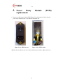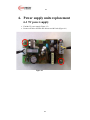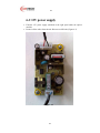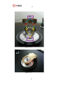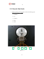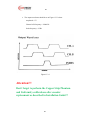
1
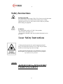
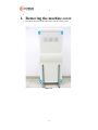
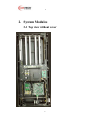
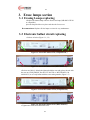
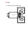
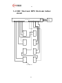
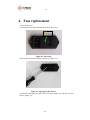
CDCR 5020s
SYSTEM
Service Manual
Ver. 040608
2
CR-Tech is marketing the CDCR5020s, an innovation in the field of compact desktop portable
Computed Radiography Technologies—designed for low-volume clinics.
CR-Tech designs, manufactures and markets phosphor image laser readers. These units replace
the existing traditional x-ray film. The readers allow the user to almost immediately read the x-ray
image from the phosphor plate, and transfer it to a digital format and allows to be used with
known protocol as DICOM 3 (Digital Imaging communication in medicine).
Once transferred to a digital format, users can manipulate the digital image for zoom in, or
transmit it via any known / available media wired or wireless for long-distance consultation.
After each scan, the phosphor plates are erased in the special compartment, ready for re-use.
The number of re-using times is the highest in the market due to the fact that no one touches
the phosphor plates.
CR-Tech provides clients with a reader that is integrated and tested with third party viewers
(with or without) database software that are giving a full reading station solution. This solution
is compatible with compact clinics or large environment that uses Picture Archiving and
Communications System (PACS).
The company’s mission is to serve the market of CR with compact solutions and become a
leading provider.
Our units can be used by medical, mobile, military, industry veterinary markets.
“We are committed to assisting our customers in obtaining maximum
value from CR-TECH products by providing excellent support at
exceptional value.”
Technical Support
USA
:
Tel: +1-631-289-7333
Fax: +1-631-289-5753
E-mail: [email protected]
Document Part Number: 2008 CR 03022008
2
3
Table of Contents
Contents
Safety Instructions .................................................................................................4
1. Removing the machine cover ..................................................................................5
2. System Modules .....................................................................................................7
2-1 Top view without cover
2-2 Mechanical parts
...................................................................................7
............................................................................................8
2-3 Electronics' .....................................................................................................9
2-4 Erase lamp area ............................................................................................10
2-5 Cassette Holder section
.................................................................................11
3. Erase lamps section ..............................................................................................12
3-1 Erasing Lamps replacing
..............................................................................12
3-2 Electronic ballast circuit replacing
3-3 Uniqtronic Electronic ballast circuit
................................................................12
..............................................................13
3-4 ERC Mectronic HPE Electronic ballast circuit ...............................................14
4. Fuse replacement .................................................................................................15
5. Power Entry Module (PEM) replacement .............................................................17
6. Power supply units replacement ...........................................................................18
6-1 5V power supply
...........................................................................................18
6-2 12V power supply
.........................................................................................19
7. DC-to-DC (±12V) converter replacing ..................................................................20
8. Zero-sensor board replacement ............................................................................21
9. LEDs board replacement .....................................................................................22
10. USB board replacement .......................................................................................24
11. Controller board replacement ..............................................................................26
12. Laser replacement ...............................................................................................27
13. Encoder ............................................................................................................28
13.1 Encoder removal ..........................................................................................28
13.2 Encoder adjustment ......................................................................................31
13.3 Encoder final check ......................................................................................35
14. Optical Module replacing.....................................................................................37
15. V-Belt tightening .................................................................................................39
3
4
Safety Instructions
LIFTING HAZARD
The CDCR5020s reader weighs 35 Kg (75 lb). Do not try to lift the reader
by yourself. Always seek assistance from another person. Lifting
equipment that is too heavy may result in serious injury to personnel
and/or damage to equipment.
WARNING
The CDCR5020s reader is a CLASS 1 Laser product.
- Do not remove the reader cover!
- Cover removal should be done only by authorized trained service
personnel!
Laser Safety Instructions
1. During normal operation, the optical compartment should
always be enclosed in its protective cover. This will prevent the
outside area from being exposed to laser light.
2. During normal operation, the cover should not be removed.
Removing the cover should only be done for service purposes
by trained service personnel.
NOTE:
ALLWAYS USE LocTiTE 84 WHEN
TIGHTENING SCREWS
4
5
•
1. Removing the machine cover
•
Disconnect the power and USB cables from the 5020s system.
Figure 1-1
5
6
•
Figure 1-2
Release the four screws of the cover with 3mm Allen key (for M4 screws)
As described in figures 1-1 and 1-2, then carefully open the CR-Reader cover.
6
7
2. System Modules
2-1 Top view without cover
7
8
Figure 2-1: Top view
2-2 Mechanical parts
Linear motion
stepper motor
Linear coupling
V-belt
Puling pulley
Plastic chain
Polygon Module Plate
Encoder plate
Laser holder
Encoder cover
Laser tightening strip
8
9
Figure 2-2: Mechanical parts
2-3 Electronics'
Internal
USB cable
Power entry
module
5V Power
supply
Zero-sensor
board
Controller
board
± 12V DC to DC
converter
Motor rotation
board
Laser diode
9
10
Figure 2-3: Electronics'
2-4 Erase lamp area
Florescent lamp
connectors
Electronic ballast
Plastic chain
Florescent lamp
connectors
Figure 2-4: Erase lamp area
10
11
2-5 Cassette Holder section
Plate elevating
flaps
Cassette
Holder module
PVC flaps
elevating guides
PVC cassette
guides
Figure 2-5 Cassette Holder section
11
12
3. Erase lamps section
3-1 Erasing Lamps replacing
• Replace the burned lamp with new fluorescent lamp (OSRAM L15W/20
or compatible),
place the lamps holder on its place and close the four screws.
Recommendation: Replace all four lamps at a time for easy maintenance.
3-2 Electronic ballast circuit replacing
• Release all wires (Figure 3-1, 3-2)
Figure 3-1: Electronic ballast wires (UNIQTRONIC)
Figure 3-2: Electronic ballast wires (MECTRONIC)
• Release two M3x12 Allen bolts tightened with the nuts and replace the unit with
the new one (UNIQTRONIC Part No.CLT/418/T8S or MECTRONIC Cod.
696929/952), or use only ballast with the same catalog number (Figure 3-3)
Figure 3-3: Electronic ballast screws (UNIQTRONIC)
Figure 3-4: Electronic ballast screws (MECTRONIC)
• Tighten two screws and connect the wires.
12
13
3-3 Uniqtronic Electronic ballast circuit
Lamp 1
1
1 2
L
N
Lamp 2
Electronic Ballast
GND
2 3
3 4
4 5
6
Lamp 3
Lamp 4
13
14
3-4 ERC Mectronic HPE Electronic ballast
circuit
N
L
GND
T ra n s fo rm e r
6
6
5
4
5
3
2
1
11
10
9
8
1
1
2
2
1
1
2
2
1
1
2
2
1
1
2
2
LAM P SO CKET
14
7
B LUE
BROW N
Y ELLO W
pow er
s u p p ly
220vA C
15
4. Fuse replacement
• Turn off the power
• Disconnect power and USB cables from the 5020s system.
Fuse
Drawer
Figure 4-1: Fuse house
• Pull out the fuse drawer with the screwdriver (Figure 4-2).
Figure 4-2: Opening the fuse drawer
• Replace the damaged fuse with 250V 2.0A (Ø5 x 20mm) fuse and close the fuse
drawer (Figure 4-3).
15
16
Fuse
Figure 4-3: Replacing the fuse
16
17
5. Power
Entry
replacement
•
Module
(PEM)
Remove two M3 screws from the PEM (Figure 5-1a), disconnect all cables from the
power entry module (Figure 5-1b) and take the module out.
Figure 5-1(a): PEM’s screws
Figure 5-1(b): PEM’s cables
• Replace the unit with the new one. Connect all disconnected cables. Tighten all screws.
17
18
6. Power supply units replacement
6-1 5V power supply
•
•
Find the 5V power supply (Figure 2-3)
Remove all cables from the unit. Release two M3 bolts (Figure 6-1)
Figure 6-1
18
19
6-2 12V power supply
•
•
Find the 12V power supply (attached to the right panel under the optical
module)
Remove all the cables from the unit. Release two M3 bolts (Figure 6-2)
Figure 6-2
19
20
7. DC-to-DC (±12V) converter
replacing
•
•
Find the ± 12V DC to DC converter (figure 2-3)
Remove all the cables from the unit. Release four M3 bolts (figure 7-1)
•
Figure 7-1
Replace the unit with the new one. Tighten all the bolts and connect all the
disconnected cables. Close the CR-Reader cover.
20
21
8. Zero-sensor board replacement
•Disconnect the power and USB cables from the 5020s system.
•Open CR-Reader cover (figure 1-1, 1-2).
•Disconnect the cable from the board.
•Release two M3 screws (figure 8-1).
M3 screws
Figure 8-1
Figure 8-2
• Replace the zero-sensor board with the new one.
• Connect cable to the zero-sensor board.
21
22
• Tighten all screws.
9. LEDs board replacement
• Disconnect the power and USB cables from the 5020s system.
• Disconnect the cable from the board.
• Release two M3 screws and remove the board with the metal adapter (figure 9-1)
Figure 9-1
• Release two M3 screws and remove the metal adapter. (figure 9-2 , 9-3, 9-4)
Figure 9-2
22
23
Figure 9-3
9
7
6
4
5
Figure 9-4
1.
2.
3.
4.
5.
6.
7.
8.
M3x10 screws
M3 washers
Led's board
M3x2.4mm plastic spacer
Led's board adapter
M3 washers
M3 spring washers
M3 nuts
• Replace the board and tighten all screws.
• Connect the cable.
23
3
2
1
24
10. USB board replacement
• Disconnect the power and USB cables from the 5020s system.
• Disconnect the cable from the board.
• Release two M3 screws and remove the board with the metal adapter (Figure10-1)
Figure 10-1
• Release two M3 screws and remove the metal adapter. (Figure 10-2, 10-3 , 10-4)
Figure 10-2
24
25
Figure 10-3
9
1.
2.
3.
4.
5.
6.
7.
8.
7
6
5
M3x10 screws
M3 washers
Led's board
M3x2.4mm plastic spacer
Led's board adapter
M3 washers
M3 spring washers
M3 nuts
• Replace the board and tighten all screws.
• Connect the cable
25
4
3
2
1
26
11. Controller board replacement
•
•
•
Disconnect the power and USB cables from the 5020s system.
Disconnect all cables from the controller board.
Release six M3 screws (Figure 11-1).
Figure 11-1
•
•
Replace the controller board with the new one.
Connect all cables to the controller.
26
27
12. Laser replacement
•
•
•
Disconnect the power and USB cables from the 5020s system.
Disconnect laser power cable.
Release four M3 screws. (figure 12-1)
Figure 12-1
•
•
Replace the laser with the new one.
Tighten four M3 screws.
27
28
13. Encoder
13.1 Encoder removal
•
•
Disconnect the power and USB cables from the 5020s system.
Release two M3 screws from the encoder cover (Figure 13.1-1).
Figure 13.1-1
•
Remove two M2.5mm cap socket head screws from static optical encoder
module. (Figure 13.1-2)
Figure 13.1-2
28
29
•
Remove encoder wheel set screw with 0.9mm (0.035’) flat screw driver.
(Figures 13.1-3, 13.1-4, 13.1-5)
Figure 13.1-3
Figure 13.1-4
29
30
Figure 13.1-5
•
Remove the encoder wheel.
Attention!!!
The encoder wheel is very flexible and soft!
Handle it carefully!
30
31
13.2 Encoder adjustment
•
Place the encoder wheel on the main polygon shaft. (USE ONLY HEDS9140 OPTICAL ENCODER MODULE AND HEDS-5140 ENCODER
CODEWHEEL) (figure 13.2-1 , 13.2-2)
Figure 13.2-1
Figure 13.2-2
31
32
•
Place the encoder optical module so that the encoder wheel is in the middle
of the encoder module slot. (figure 13.2-3)
Figure 13.2-3
•
•
Tighten the encoder wheels set screw and lightly tight the two encoder
module cap socket head M2.5mm screws.
Place the encoder calibration device so that the device pins will fit into the
encoder optical module calibration holes (Figure 13.2-4, 13.2-5) and the
encoder wheel set screw fit in. (figure 13.2-6)
Figure 13.2-4
32
33
Pins
Holes
Figure 13.2-5
Figure 13.2-6
33
34
•
Tight the encoder optical module screws and remove the encoder calibration
device. (figure 13.2-7)
Figure 13.2-7
34
35
13.3 Encoder final check
•
With the oscilloscope check the output waveforms in the following points
(during nominal rotation – 15 RPS):
1. Channel B
2. Vcc
3. Channel A
4. Index
5. GND
1
2
3
Figure 13.3-1
35
4
5
36
•
The output waveforms should be as on Figure 13.3-2 when:
Amplitude = 5V
Channel A/B frequency = 30000 Hz
Index frequency = 25 Hz
Figure 13.3-2
Attention!!!
Don’t forget to perform the Copper Strip Phantom
and Uniformity calibrations after encoder
replacement as described in Installation Guide!!!
36
37
14. Optical Module replacing
•
•
Remove the CR-Reader cover. (paragraph 1)
Unplug the following cables (figure 14-1):
1- Encoder board cable
2- Driver cable
3- Laser cable (unplug from the controller)
Driver cable
Laser cable
Figure 14-1
Encoder board
37
38
•
Release the four M5x16 Allen screws (figure 14-2)
Figure 14-2
•
•
Replace the bridge carefully.
Connect the cables.
38
39
15. V-Belt tightening
•
Find the V-Belt and the Linear Motion Stepper motor
(Figures: 2.2: mechanical parts, 15-1)
V-Belt
Figure 15-1
39
40
•
Using M5 Allen key tighten the 2 left screws which are connecting the
Linear Motion Stepper motor to the CR-Reader body (figures 15-2 ,15-3)
Figure 15-2
Attention!!!
Tightening the V-Belt too much, can cause artifacts on the image.
40