1
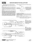
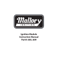
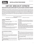
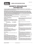
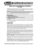
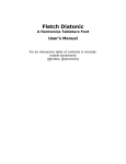
INSTALLATION INSTRUCTIONS ® FORM #1263M (REV. F) 01/01 UNILITE® BREAKERLESS IGNITION CONVERSION KIT 1957-74 FORD/MOTORCRAFT 8-CYLINDER SINGLE POINT DISTRIBUTORS PART NO. 502 IMPORTANT: Before starting the installation of the UNILITE® Ignition System, make sure that the vehicle is equipped with an ignition ballast resistor (or loom resistance wire) in the wire between the ignition switch and the coil (+) terminal. One easy way to find the ignition ballast resistor is to check the service manual for your vehicle. You can test your stock ignition system voltage while the engine is at idle at the coil (+) terminal. If the measured voltage is within 1 volt of battery voltage, an ignition ballast resistor must be installed in the wire from the ignition switch. Example: Vehicles with a Ford TFI or Delco HEI require adding an ignition ballast resistor in the wire from the ignition switch. If you find your vehicle is not equipped with an ignition ballast resistor, install a Mallory Ignition Ballast Resistor Part No. 700 in series in the wire from the ignition switch. Failure to use an ignition ballast resistor will result in the eventual destruction of the UNILITE® Ignition Module. Exception: If your vehicle is equipped with a HYFIRE® Electronic Ignition Control or similar aftermarket ignition control, use ignition ballast resistors and wiring procedures as stated in the instructions for the particular ignition control. NOTE: This kit can be installed in the distributor without removing the distributor from the engine if the distributor is easily accessible. However, removal of the distributor from the engine is recommended. LIST OF PARTS: 1 1 1 1 1 UNILITE® Module Part No. 605 Rotor/Shutter Wheel Part No. 333 Distributor Wire Harness Part No. 29349 Female connector Upper mounting plate 1 2 2 1 1 1 Lower mounting plate Screws, 6-32 x 3/16" Flathead screws, 8-32 x 1/4" Flathead screw, 8-32 x 3/8" Capsule, white silicone grease Grommet GENERAL INFORMATION IGNITION COILS The UNILITE® Ignition System is designed to work with most stock ignition coils and aftermarket high performance ignition coils. For optimum performance, use a Mallory PROMASTER® Coil Part No. 29440 or 29625, or Mallory Chrome Electronic Ignition Coil Part No. 29216. ELECTRIC WIRING Unplug the distributor wire harness before welding on the vehicle. OPTIONAL ACTIVE POWER FILTER PART NO. 29351 Voltage spikes (voltage transients, power surges) are associated with noisy electrical systems from electrical defects such as worn alternator brushes, corroded or oxidized electrical connections and similar electrical problems. SPARK PLUG WIRES To prevent false triggering and the possibility of premature ignition failures, use This device protects the UNILITE® Ignition Module against voltage spikes. suppression-type spark plug wire. We recommend spiral core ignition wire, such as Mallory PRO SIDEWINDER® Ignition Wire. SPARK PLUG GAPS For street applications, use your engine manufacturers specifications. For racing applications, start with your engine manufacturers specifications, then experiment with and closely monitor various gaps to achieve maximum performance. 1 INSTALLATION PROCEDURE Step 1 Disconnect the point trigger wire from the coil () terminal. Step 2 Locate the #1 cylinders spark plug wire on the distributor cap. See a service manual for these locations. Mark the distributor cap and the distributor housing, in line with #1 cylinders spark plug wire position on the distributor cap. Step 3 Turn the engine crankshaft in the direction of rotation until the timing mark lines up with the top dead center (TDC) mark on the timing tab. See a service manual for these locations. NOTE: Removing the spark plugs may make it easier to turn the crankshaft. Step 4 Remove the distributor cap from the distributor and lay it aside. Do not remove the spark plug wires or coil wire. The rotor blade should point to the mark made on the distributor housing (from Step 2). If it is not, turn the engine crankshaft in the direction of rotation one full turn (repeating Step 3) until the timing mark lines up (again) with the TDC mark on the timing tab. NOTE: Once you are finished with Step 4, DO-NOT turn the crankshaft until the UNILITE® Conversion Kit and distributor is installed (Step 12). Step 5 Note the direction the rotor is pointing. Note the direction the vacuum chamber is pointing. Remove the distributor hold down clamp and remove the distributor from the engine. Step 6 Remove the rotor. Disconnect the primary point wire. Remove the primary wire and the grommet from the distributor. Remove the breaker point and the condenser from the breaker plate. Install the ground wire to the breaker plate using the condenser screw. Step 8 Position the upper mounting plate with its countersunk holes aligned with the holes in the lower mounting plate. Install one 8-32 x 3/8" flathead screw through the non-threaded hole in the lower mounting plate into the breaker plate. Install one 8-32 x 1/4" flathead screw into the threaded hole in the lower mounting plate. Make sure to tighten these screws firmly. Step 9 Apply a thin coat of white silicone grease to the bottom of the UNILITE® Module. Install the UNILITE® Module onto the upper mounting plate with two 6-32 screws. Make sure to tighten these screws firmly. Step 10 The grommet has a flat on one flange. Install the grommet in the hole in the distributor housing where the primary wire had previously fed through with the flat on one flange facing out and up. Positioning the flat on one flange facing out and up allows adequate distributor cap clearance. Slide the three wires from the UNILITE® Module, through the grommet, to outside the distributor housing. Step 11 Put the UNILITE® Modules three wires in the female connector: GREEN WIRE in hole #1 BROWN WIRE in hole #2 RED WIRE in hole #3 Plug the female connector into the distributor wire harness. See Figure 1. Step 12 Install the rotor/shutter. Place the distributor in the engine with the rotor pointing in the same general direction as during removal of the distributor (from Step 5). NOTE: The distributor must be fully seated into the engine. It may be necessary to turn the oil pump drive, or turn the engine crankshaft in the direction of rotation two full turns until the timing mark lines up (again) with the TDC mark on the timing tab to allow the distributor to seat fully. Step 13 Rotate the distributor housing until the rotor points to the mark on the distributor Step 7 housing (from Step 2) and the nearest slot on the rotors shutter wheel is Position the lower mounting plate (with one countersunk hole) against the approximately in the center of the optics of the UNILITE® Module. This will breaker plate. Align the countersunk hole over one existing breaker plate generally put timing close enough for starting purposes. Put the distributor hold threaded hole. Align one non-threaded hole with the other breaker plate down clamp in place and tighten slightly, leaving it loose enough to turn the threaded hole. Install one 8-32 x 3/8" flathead screw through the nondistributor housing. threaded hole (temporarily, do not tighten) to help in the alignment of the lower mounting plate onto the breaker plate. Install one 8-32 x 1/4" flathead screw Step 14 through the countersunk hole and tighten firmly into the breaker plate. Install the distributor cap. NOTE: The grommet was installed during step 10. The grommet has a flat on one flange. When installed, the flat on the flange of Remove the 8-32 x 3/8" flathead screw. the grommet must face out and up to allow adequate distributor cap clearance. The distributor cap may not sit properly on the distributor housing unless these details are followed exactly. FIGURE 1 2 WIRING PROCEDURE FIGURE 2 SEE FIGURES 3 AND 4 IMPORTANT: Make sure that your vehicle is equipped with an ignition ballast resistor (or loom resistance wire) in the wire between the ignition switch and the coil (+) terminal. One easy way to find the ignition ballast resistor is to check the service manual for your vehicle. In general, all vehicles equipped with the Ford/Motorcraft point ignition were equipped with an ignition ballast resistor. If you find your vehicle is not equipped with an ignition ballast resistor, install a Mallory Ignition Ballast Resistor Part No. 700 in series in the wire from the ignition switch. Failure to use an ignition ballast resistor will result in the eventual destruction of the UNILITE® Ignition Module. Exception: If your vehicle is equipped with a HYFIRE® Electronic Ignition Control or similar aftermarket ignition control, use ignition ballast resistors and wiring procedures as stated in the instructions for the particular ignition control. NOTE: If your vehicle is equipped with a HYFIRE® Electronic Ignition Control or similar aftermarket ignition control, use ignition ballast resistors and wiring procedures as stated in the instructions for the particular ignition control. ADDITIONAL CONNECTIONS Tachometer operation: Connect tachometer wire or wires as recommended by the actual tachometer manufacturer. STARTING ENGINE CAUTION: Be sure all tools, wires and miscellaneous objects are clear of moving engine parts and extreme heat before starting the engine. Step 1 Recheck all wires and connections to make sure they are correct. Check and clean, or replace, spark plugs. If replacing spark plugs, use types recommended by the engine manufacturer. Step 2 Connect a timing light. Find the area with the best view of the timing marks. Step 3 Start the engine. If it fails to start, rotate the distributor housing in small increments clockwise or counterclockwise until engine starts. Do not exceed more than 10 degrees of distributor housing rotation in either direction. Step 4 Set timing as recommended by engine manufacturer, then tighten distributor hold down clamp. Make sure timing is still correct. If timing has moved, repeat this procedure. DISTRIBUTOR TUNE-UP PARTS DESCRIPTION PART NO. DISTRIBUTOR CAP ROTOR/SHUTTER WHEEL UNILITE® MODULE 217 333 605 3 FIGURE 3 You must use suppressor coil wire COIL NOTE: When using the UNILITE ® distributor with a HYFIRE ® or other aftermarket amplifier box, connect the distributor according to the amplifier box instructions. A PROMASTER® coil is shown for illustration purposes. When using a stock coil, connect it in the same manner shown. + RED OEM PRIMARY RESISTANCE WIRE – TO IGNITION SWITCH DISTRIBUTOR (TYPICAL) BROWN DISTRIBUTOR WIRE HARNESS GREEN GROUND TO ENGINE BLOCK FIGURE 4 You must use suppressor coil wire COIL NOTE: When using the UNILITE ® distributor with a HYFIRE ® or other aftermarket amplifier box, connect the distributor according to the amplifier box instructions. MALLORY BALLAST RESISTOR PN 700 OR OEM BALLAST RED + TO IGNITION SWITCH – A PROMASTER® coil is shown for illustration purposes. When using a stock coil, connect it in the same manner shown. DISTRIBUTOR (TYPICAL) BROWN GREEN DISTRIBUTOR WIRE HARNESS GROUND TO ENGINE BLOCK MALLORY IS A DIVISION OF THE MR. GASKET PERFORMANCE GROUP 550 MALLORY WAY, CARSON CITY, NEVADA 89701 (775) 882-6600 FAX (775) 887-4326 www.mrgasket.com 4 FORM #1263M (REV. F) 01/01 Made in U.S.A. Printed in U.S.A.