1
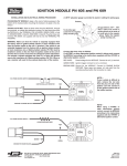
WIRING PROCEDURE
FIGURE 2
SEE FIGURES 3 AND 4
IMPORTANT: Make sure that your vehicle is equipped with an
ignition ballast resistor (or loom resistance wire) in the wire
between the ignition switch and the coil (+) terminal. One easy
way to find the ignition ballast resistor is to check the service
manual for your vehicle. In general, all vehicles equipped with
the Ford/Motorcraft point ignition were equipped with an ignition
ballast resistor. If you find your vehicle is not equipped with an
ignition ballast resistor, install a Mallory Ignition Ballast Resistor
Part No. 700 in series in the wire from the ignition switch. Failure
to use an ignition ballast resistor will result in the eventual
destruction of the UNILITE® Ignition Module. Exception: If your
vehicle is equipped with a HYFIRE® Electronic Ignition Control
or similar aftermarket ignition control, use ignition ballast resistors and wiring procedures as stated in the instructions for the
particular ignition control.
NOTE: If your vehicle is equipped with a HYFIRE® Electronic
Ignition Control or similar aftermarket ignition control, use ignition
ballast resistors and wiring procedures as stated in the instructions for the particular ignition control.
ADDITIONAL CONNECTIONS
Tachometer operation: Connect tachometer wire or wires as
recommended by the actual tachometer manufacturer.
STARTING ENGINE
CAUTION: Be sure all tools, wires and miscellaneous objects
are clear of moving engine parts and extreme heat before
starting the engine.
Step 1
Recheck all wires and connections to make sure they are
correct. Check and clean, or replace, spark plugs. If replacing
spark plugs, use types recommended by the engine manufacturer.
Step 2
Connect a timing light. Find the area with the best view of the
timing marks.
Step 3
Start the engine. If it fails to start, rotate the distributor housing in
small increments clockwise or counterclockwise until engine
starts. Do not exceed more than 10 degrees of distributor
housing rotation in either direction.
Step 4
Set timing as recommended by engine manufacturer, then
tighten distributor hold down clamp. Make sure timing is still
correct. If timing has moved, repeat this procedure.
DISTRIBUTOR TUNE-UP PARTS
DESCRIPTION
PART NO.
DISTRIBUTOR CAP
ROTOR/SHUTTER WHEEL
UNILITE® MODULE
217
333
605
3