1
Model 4002P
Portable Power Supply
Operating and Service Manual
Printed in U.S.A.
ORTEC® Part No. 740310
Manual Revision D
1202
Advanced Measurement Technology, Inc.
a/k/a/ ORTEC®, a subsidiary of AMETEK®, Inc.
WARRANTY
ORTEC* warrants that the items will be delivered free from defects in material or workmanship. ORTEC makes
no other warranties, express or implied, and specifically NO WARRANTY OF MERCHANTABILITY OR
FITNESS FOR A PARTICULAR PURPOSE.
ORTEC’s exclusive liability is limited to repairing or replacing at ORTEC’s option, items found by ORTEC to
be defective in workmanship or materials within one year from the date of delivery. ORTEC’s liability on any
claim of any kind, including negligence, loss, or damages arising out of, connected with, or from the performance
or breach thereof, or from the manufacture, sale, delivery, resale, repair, or use of any item or services covered
by this agreement or purchase order, shall in no case exceed the price allocable to the item or service furnished
or any part thereof that gives rise to the claim. In the event ORTEC fails to manufacture or deliver items called
for in this agreement or purchase order, ORTEC’s exclusive liability and buyer’s exclusive remedy shall be release
of the buyer from the obligation to pay the purchase price. In no event shall ORTEC be liable for special or
consequential damages.
Quality Control
Before being approved for shipment, each ORTEC instrument must pass a stringent set of quality control tests
designed to expose any flaws in materials or workmanship. Permanent records of these tests are maintained for
use in warranty repair and as a source of statistical information for design improvements.
Repair Service
If it becomes necessary to return this instrument for repair, it is essential that Customer Services be contacted in
advance of its return so that a Return Authorization Number can be assigned to the unit. Also, ORTEC must be
informed, either in writing, by telephone [(865) 482-4411] or by facsimile transmission [(865) 483-2133], of the
nature of the fault of the instrument being returned and of the model, serial, and revision ("Rev" on rear panel)
numbers. Failure to do so may cause unnecessary delays in getting the unit repaired. The ORTEC standard
procedure requires that instruments returned for repair pass the same quality control tests that are used for
new-production instruments. Instruments that are returned should be packed so that they will withstand normal
transit handling and must be shipped PREPAID via Air Parcel Post or United Parcel Service to the designated
ORTEC repair center. The address label and the package should include the Return Authorization Number
assigned. Instruments being returned that are damaged in transit due to inadequate packing will be repaired at the
sender's expense, and it will be the sender's responsibility to make claim with the shipper. Instruments not in
warranty should follow the same procedure and ORTEC will provide a quotation.
Damage in Transit
Shipments should be examined immediately upon receipt for evidence of external or concealed damage. The carrier
making delivery should be notified immediately of any such damage, since the carrier is normally liable for damage
in shipment. Packing materials, waybills, and other such documentation should be preserved in order to establish
claims. After such notification to the carrier, please notify ORTEC of the circumstances so that assistance can be
provided in making damage claims and in providing replacement equipment, if necessary.
Copyright © 2002, Advanced Measurement Technology, Inc. All rights reserved.
*ORTEC® is a registered trademark of Advanced Measurement Technology, Inc. All other trademarks used
herein are the property of their respective owners.
iii
CONTENTS
WARRANTY . . . . . . . . . . . . . . . . . . . . . . . . . . . . . . . . . . . . . . . . . . . . . . . . . . . . . . . . . . . . . . . . . . . . . . . ii
SAFETY INSTRUCTIONS AND SYMBOLS . . . . . . . . . . . . . . . . . . . . . . . . . . . . . . . . . . . . . . . . . . . . . . . iv
SAFETY WARNINGS AND CLEANING INSTRUCTIONS . . . . . . . . . . . . . . . . . . . . . . . . . . . . . . . . . . . . . v
1. DESCRIPTION . . . . . . . . . . . . . . . . . . . . . . . . . . . . . . . . . . . . . . . . . . . . . . . . . . . . . . . . . . . . . . . . . . . 1
1.1. GENERAL . . . . . . . . . . . . . . . . . . . . . . . . . . . . . . . . . . . . . . . . . . . . . . . . . . . . . . . . . . . . . . . . . . 1
2. SPECIFICATIONS . . . . . . . . . . . . . . . . . . . . . . . . . . . . . . . . . . . . . . . . . . . . . . . . . . . . . . . . . . . . . . . .
2.1. PERFORMANCE . . . . . . . . . . . . . . . . . . . . . . . . . . . . . . . . . . . . . . . . . . . . . . . . . . . . . . . . . . . . .
2.2. CONTROLS AND INDICATORS . . . . . . . . . . . . . . . . . . . . . . . . . . . . . . . . . . . . . . . . . . . . . . . . .
2.3. INPUTS . . . . . . . . . . . . . . . . . . . . . . . . . . . . . . . . . . . . . . . . . . . . . . . . . . . . . . . . . . . . . . . . . . . .
2.4. OUTPUTS . . . . . . . . . . . . . . . . . . . . . . . . . . . . . . . . . . . . . . . . . . . . . . . . . . . . . . . . . . . . . . . . . .
2.5. ELECTRICAL AND MECHANICAL . . . . . . . . . . . . . . . . . . . . . . . . . . . . . . . . . . . . . . . . . . . . . . . .
2.6. ACCESSORIES . . . . . . . . . . . . . . . . . . . . . . . . . . . . . . . . . . . . . . . . . . . . . . . . . . . . . . . . . . . . . .
2.7. ORDERING INFORMATION . . . . . . . . . . . . . . . . . . . . . . . . . . . . . . . . . . . . . . . . . . . . . . . . . . . .
1
1
2
2
2
3
3
3
3. INSTALLATION . . . . . . . . . . . . . . . . . . . . . . . . . . . . . . . . . . . . . . . . . . . . . . . . . . . . . . . . . . . . . . . . . .
3.1. UNPACKING . . . . . . . . . . . . . . . . . . . . . . . . . . . . . . . . . . . . . . . . . . . . . . . . . . . . . . . . . . . . . . . .
3.2. SELECTING THE MAINS VOLTAGE . . . . . . . . . . . . . . . . . . . . . . . . . . . . . . . . . . . . . . . . . . . . . .
3.3. REPLACING THE FUSES . . . . . . . . . . . . . . . . . . . . . . . . . . . . . . . . . . . . . . . . . . . . . . . . . . . . . .
3.4. LOCATION . . . . . . . . . . . . . . . . . . . . . . . . . . . . . . . . . . . . . . . . . . . . . . . . . . . . . . . . . . . . . . . . . .
3.5. COMPATIBILITY . . . . . . . . . . . . . . . . . . . . . . . . . . . . . . . . . . . . . . . . . . . . . . . . . . . . . . . . . . . . .
4
4
4
4
4
5
4. OPERATING INSTRUCTIONS . . . . . . . . . . . . . . . . . . . . . . . . . . . . . . . . . . . . . . . . . . . . . . . . . . . . . . .
4.1. CONTROL PANEL FUNCTIONS . . . . . . . . . . . . . . . . . . . . . . . . . . . . . . . . . . . . . . . . . . . . . . . . .
4.2. POWER SUPPLY LIMITATIONS . . . . . . . . . . . . . . . . . . . . . . . . . . . . . . . . . . . . . . . . . . . . . . . . .
4.3. CONNECTION AND DISCONNECTION . . . . . . . . . . . . . . . . . . . . . . . . . . . . . . . . . . . . . . . . . . .
5
5
5
5
5. CIRCUIT DESCRIPTION . . . . . . . . . . . . . . . . . . . . . . . . . . . . . . . . . . . . . . . . . . . . . . . . . . . . . . . . . . . 5
6. CALIBRATION AND MAINTENANCE . . . . . . . . . . . . . . . . . . . . . . . . . . . . . . . . . . . . . . . . . . . . . . . . . .
6.1. POWER SUPPLY DISASSEMBLY AND TROUBLESHOOTING . . . . . . . . . . . . . . . . . . . . . . . . .
6.2. DC OUTPUT VOLTAGE LEVEL ADJUSTMENTS . . . . . . . . . . . . . . . . . . . . . . . . . . . . . . . . . . . .
6.3. FACTORY REPAIR . . . . . . . . . . . . . . . . . . . . . . . . . . . . . . . . . . . . . . . . . . . . . . . . . . . . . . . . . . .
6
6
6
7
iv
SAFETY INSTRUCTIONS AND SYMBOLS
This manual contains up to three levels of safety instructions that must be observed in order to avoid
personal injury and/or damage to equipment or other property. These are:
DANGER
Indicates a hazard that could result in death or serious bodily harm if the safety instruction is
not observed.
WARNING
Indicates a hazard that could result in bodily harm if the safety instruction is not observed.
CAUTION
Indicates a hazard that could result in property damage if the safety instruction is not
observed.
Please read all safety instructions carefully and make sure you understand them fully before attempting to
use this product.
In addition, the following symbol may appear on the product:
ATTENTION – Refer to Manual
DANGER – High Voltage
Please read all safety instructions carefully and make sure you understand them fully before attempting to
use this product.
v
SAFETY WARNINGS AND CLEANING INSTRUCTIONS
DANGER
Opening the cover of this instrument is likely to expose dangerous voltages. Disconnect the
instrument from all voltage sources while it is being opened.
WARNING Using this instrument in a manner not specified by the manufacturer may impair the
protection provided by the instrument.
Cleaning Instructions
To clean the instrument exterior:
! Unplug the instrument from the ac power supply.
! Remove loose dust on the outside of the instrument with a lint-free cloth.
! Remove remaining dirt with a lint-free cloth dampened in a general-purpose detergent and water
solution. Do not use abrasive cleaners.
CAUTION To prevent moisture inside of the instrument during external cleaning, use only enough liquid
to dampen the cloth or applicator.
!
Allow the instrument to dry completely before reconnecting it to the power source.
vi
1
ORTEC MODEL 4002P
PORTABLE POWER SUPPLY
1. DESCRIPTION
1.1. GENERAL
The ORTEC Model 4002P Portable Power Supply
is ideally suited for providing power to
preamplifiers, or to a NIM module in a remote
location. It is an effective solution when the
additional power, size, or cost of a standard NIM bin
is inconvenient.
DC power is provided by the Model 4002P for four
preamplifiers through standard 9-pin connectors on
the rear panel. These connectors deliver ±12 and
±24 V dc, and are compatible with ORTEC standard
preamplifier power cables, as well as those of most
NIM manufacturers. The Model 4002P can supply
power for up to 12 preamplifiers by adding an
optional Model 4002P-C1 Preamp Power Fan-Out
Cable to each connector. The fan-out cable
converts a single preamp power output connector to
three separate preamp power output connectors.
A standard NIM bin power connector is incorporated
for supplying ±12 V dc and ±24 V dc to a NIM
module. Connection between the 4002P and the
NIM module is made with the ORTEC Model
401-C3 Module Extender Cable, which can be
ordered as an accessory. The output power is
sufficient to operate a four-wide NIM module and
four preamplifiers.
100, 120, 220, and 240 V ac at 47 to 63 Hz. A
connector block on the rear panel is used to change
and display the selected input voltage. Also
incorporated in this connector block are a fuse
holder and the input power cord connector. The
4002P uses an international standard IEC power
connector to permit the use of power cords and
plugs that meet local electrical standards.
The Model 4002P has maximum output current
ratings of 1 A on +12 V, 1 A on !12 V, 0.5 A on
+24 V, and 0.5 A on !24 V.
There are three levels of protection against
overload. A fuse on the ac power connector limits
the input current. All dc outputs include a current
foldback circuit to limit the output current to
nominally 150% of the rated value. This feature
provides short-circuit and overload protection.
Recovery is automatic after removal of the
overload condition. Test points are conveniently
located on the front panel to allow monitoring the
status of the dc outputs. A temperature warning
light on the front panel turns on when the heat sink
temperature rises above 82°C. When the
temperature of the heat sink exceeds 95°C, the
power supply is automatically turned off. Recovery
is automatic when the load is reduced and the
temperature decreases to a safe value.
Designed for international use, the 4002P Portable
Power Supply can accommodate input voltages of
2. SPECIFICATIONS
2.1. PERFORMANCE
INPUT AC VOLTAGE
The primary voltage
selection card and indicator located in the AC
POWER connector assembly permit operation with
100 V, 120 V, 220 V, or 240 V nominal input
voltages. lnput voltage ranges accommodated on
each setting are:
Nominal
Voltage (ac)
100
120
220
240
Regulation
Range (V ac)
88–110
103–129
191–239
206–258
FREQUENCY RANGE Operating range for ac
input voltage frequency is 47–63 Hz.
2
INPUT CURRENT
Typically, 0.8 A rms with a
48-W dc load and a 120-V ac input. Protected with
a 2-A fuse on the 100- and 120-V ac settings, and
by a 1-A fuse on the 220- and 240-V ac settings.
DC OUTPUT Maximum rated output currents are:
DC Voltage
+12 V
!12 V
+24 V
!24 V
Maximum Current
1A
1A
0.5 A
0.5 A
Maximum dc output power from 0 to 50°C is 48W.
Derate 2.5%/°C for 50 to 60°C.
DC REGULATION
Variations in dc output
voltages are <±0.1 % over the combined range of
zero through full load and input voltages from the
minimum to maximum limits of the allowed input
voltage range. Measurements are made within a 1
-minute period. Regulation <±0.3% over any 24hour period at constant ambient temperature for the
same load and input voltage ranges after a 60minute warmup.
LONG-TERM STABILITY DC output voltages
change <±0.5% (after a 60-minute warmup) over a
6-month period at constant load, input voltage, and
ambient temperature.
S
OUTPUT IMPEDANCE <0.3 at any frequency
up to 100 kHz for the dc outputs.
TEMPERATURE COEFFICIENT <0.02%/°C from
0 to 60°C for the dc outputs.
NOISE AND RIPPLE <3 mV peak-to-peak for any
dc output, as observed on a 50-MHZ bandwidth
oscilloscope.
VOLTAGE ADJUSTMENT ±5% minimum range.
Range typically ±1 V about the nominal supply
voltage. Resettability <±0.05% of the supply
voltage.
:
RECOVERY TIME <50 s to return to within
±0.1% of the rated voltage for all dc outputs for any
input voltage change within the rated range, or for
a change of load current from 10 to 100% of full
load.
side-panel heat sink is within 13°C of the maximum
operating temperature limit When the heat sink
temperature exceeds the 95°C maximum limit, a
thermal switch automatically turns off the power
supply. Under this thermal shut-down condition,
both the TEMP and the POWER lights are turned
off. Recovery from thermal shut-down is automatic
once the load is reduced, so that the heat sink
temperature drops below the maximum operating
limit.
CIRCUIT PROTECTION Fuse Rating: 2 A (FAST)
size 3AG fuse for 100-V or 120-V operation; 1 A(F)
size 5×20 mm fuse for 220-V or 240-V operation.
All dc outputs include a current foldback circuit to
limit the output current to nominally 150% of the
rated value. This feature provides short-circuit and
overload protection. Recovery is automatic after
removal of the overload condition.
2.2. CONTROLS AND INDICATORS
POWER Front-panel two-position rocker switch
turns power on or off. Adjacent red light indicates
power On condition when illuminated. Power
indicator light and output power turn off if the heat
sink temperature exceeds 95°C.
TEMP Front-panel red light turns on when the heat
sink temperature exceeds 82°C to warn that the
shutdown temperature limit is being approached.
TEMP light turns off if power has been shut off by
exceeding the heat sink temperature limit.
2.3. INPUTS
AC POWER Rear-panel, Corcom™, internationalstandard IEC power connector, type CEE-22,
accepts power cables wired according to local
electrical standards. A power cable is shipped with
the 4002P. The Corcom CEE-22 connector meets
standard 22 of the International Commission on
Rules for the Approval of Electrical Equipment. The
primary voltage selector and primary fuse are
incorporated into the AC POWER connector. The
primary voltage selected (100, 120, 220, or 240 V)
is visible through the rear door. U.S.A. standard inline fuse is 2 A for 100 or 120 V ac and 1 A for 220
or 240 V ac. See Sections 3.2 and 3.3, respectively,
for instructions on changing the voltage setting and
fuse.
2.4. OUTPUTS
THERMAL PROTECTION The red, front-panel,
TEMP light turns on when the temperature of the
PREAMP 1, PREAMP 2, PREAMP 3, PREAMP 4
Rear-panel, 9-pin, "D" connectors (Amphenol
3
17-10090) provide power for up to four
preamplifiers. Connectors mate with power cords on
all standard ORTEC preamplifiers. Compatible with
preamplifier power cables of most other NIM
manufacturers. Pin assignments are listed in
Table 1. Each preamp power output connector can
be expanded to three output connectors by using
the optional Model 4002P-C1 Preamp Power FanOut Cable. Using four of the Model 4002P-C1
allows the 4002P to supply power to 12
preamplifiers.
OUTPUT TEST POINTS
Front-panel jacks
provide test points to monitor each of the dc
voltages delivered to the rear-panel connectors..
2.5. ELECTRICAL AND MECHANICAL
WEIGHT
Net 10.9 kg (24 lb)
Shipping 13 kg (29 lb).
DIMENSIONS 21.5 cm W × 26 cm D × 10.2 cm H
(8.4 in. W × 10.2 in. D × 4.0 in. H).
Table 1. Pin Assignments for Preamp Power
Connectors.
Pin Number
1
2
3
4
5
6
7
8
9
Power Voltage
Ground
Ground
No connection
+12 V
No connection
-24 V
+24 V
No connection
-12 V
NIM POWER
Rear-panel, NIM standard bin
connector compatible with the power connector on
the rear of NIM modules, per TID-20893 (Rev). For
use with a Module Extender Cable, such as
ORTEC Model 401-C3, to power a single NIM
module. Pin assignments are listed in Table 2. Pins
not listed have no connection in the Model 4002P,
but may be assigned to a specific function by
TID-20893 (Rev).
Table 2. Pin Assignments as Wired for the NIM
POWER Connector on the Model 4002P.
Pin Number
16
17
28
29
34
42
Power Voltage
+12 V
!12 V
+24 V
!24 V
Power Return Ground
High-Quality Ground
2.6. ACCESSORIES
121-Cl PREAMPLIFIER POWER CABLE
EXTENDER Provides a 3-m (10-ft) extension
cable to connect a preamplifier power cable to the
PREAMP 1, 2, 3, or 4 power output on the 4002P
Portable Power Supply. Compatible with all
standard ORTEC preamplifiers.
401-C3 MODULE EXTENDER CABLE Connects
the 4002P NIM POWER output to the standard bin
power connector on the rear of a NIM module.
Permits powering a NIM module in a remote
location using the 4002P Portable Power Supply.
Cable length is 91 cm (3 ft).
4002P-C1 PREAMP POWER FAN-OUT CABLE
Plugs into a standard ORTEC preamplifier power
output connector and provides three preamplifier
power output connectors. Use four of the optional
4002P-C1 with the 4002P to power 12
preamplifiers.
2.7. ORDERING INFORMATION
To order the 4002P Portable Power Supply and/or
accessories, specify the following model numbers
and descriptions.
Model
4002P
121-01
401 -C3
4002P-C1
Description
Portable Power Supply
Preamplifier Power Cable Extender
Module Extender Cable
Preamp Power Fan-Out Cable
4
3. INSTALLATION
3.1. UNPACKING
Unpack the unit, being careful to retain all packing
materials until the unit has been checked for
possible concealed damage. The power cord is
packed with the unit and attaches to a 3-pin
connector that is mounted on the rear of the 4002P
Portable Power Supply
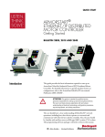
3.2. SELECTING THE MAINS VOLTAGE
The 4002P uses a Corcom Power Entry Module
(Fig. 1), which contains the power connector; a
small, removable drum for setting the line voltage;
and a line fuse. The removable drum lets you
configure the instrument for a nominal 100, 120,
220, or 240 V ac. The module door has a small
window that shows the line voltage setting now in
use.
the module door. You are now ready to reconnect
the instrument to the ac power source.
3.3. REPLACING THE FUSES
The 4002P requires the following fuses:
!
!
For 100 or 120 V ac line voltage, a 2-A (FAST)
size 3AG fuse.
For 220 or 240 V ac line voltage, a 1 A(F) size
5×20-mm fuse.
The 3AG fuse requires a Corcom LA200 fuseholder.
The 5×200-mm fuse requires a Corcom LA201
fuseholder. (We supply the appropriate fuse and
fuseholder based on your order specifications.)
CAUTION Do not use makeshift fuses or short-circuit the fuse
holders.
NOTE The spindles on each side of the drum are octagonal, not
round. This gives each of the 4 settings a definite detent.
To avoid eroding these detents, always remove the drum
before rotating it.
To replace a fuse:
Fig. 1. Setting the Line Voltage and Replacing the
Fuses.
To change the ac input voltage:
Disconnect the instrument from the ac power
source. Use a small flat-blade screwdriver or similar
tool to pop open the module door. Remove the
plastic drum: pinch the sides of the drum with your
fingernails and pull, or insert a flat-blade
screwdriver in the slot between the 120Vac and
240Vac settings and gently pry the drum loose, one
end at a time. Rotate the drum until the desired line
voltage setting will show in the door window, and
firmly press the drum back into the holder. Close
Disconnect the instrument from the ac power
source. Use a small flat-blade screwdriver or similar
tool to pop open the module door. The line fuse is
in a plastic fuseholder drawer marked with an arrow
(
). Gently pull the fuseholder out and replace
the fuse. If changing to the metric type fuse be sure
to install the corresponding fuse holder. Slide the
fuseholder back into the module and close the
module door. You are now ready to reconnect the
instrument to the ac power source.
3.4. LOCATION
The ORTEC 4002P Portable Power Supply is a
completely portable, self-contained unit that is
designed for table-top installation. The basic design
of the cabinet provides for cooling of the power
supply by natural convection flow. The power
supply should not be positioned so as to block the
flow of air around and through the cabinet. Avoid
locating the power supply near or above heat-
5
producing equipment without accounting for the
temperature rise.
3.5. COMPATIBILITY
The ORTEC 4002P Portable Power Supply is
compatible with the principles of DOE Report TID20893 (Rev), January 1968, "Standard Nuclear
Instrument Modules." This report, the work of a
committee of equipment users from AEC-related
institutions, establishes standards for a modular
instrument system which allow electrical and
mechanical interchangeability of units made in
conformance with the standards. The standards
prescribe the necessary mechanical dimensions
and connector types to ensure mechanical
interchangeability. They also specify standard
power supply voltages and pin assignments in the
connector so that electrical interchangeability is
assured, at least with respect to the main connector
joining the module to the bin.
The 4002P Portable Power Supply is a complete
assembly. It furnishes the power that is distributed
to the module connectors through the assigned
pins. A power ground return, a high-quality signal
ground, and +12 V, !12 V, +24 V, and !24 V are
included in the distribution circuits. The power
supply accepts input power from 100, 120. 220, or
240 V ac mains, 47–63 Hz.
4. OPERATING INSTRUCTIONS
4.1. CONTROL PANEL FUNCTIONS
4.2. POWER SUPPLY LIMITATIONS
An On-Off switch interrupts both sides of the input
power line. A Power pilot lamp indicates that ac
input power is being supplied to the power
transformer primary. Either a blown fuse or a
temperature cutout will extinguish this lamp.
The power supply capability is stated on the front
control panel. The user should verify that the power
supply capability is not exceeded when module
connections are made.
4.3. CONNECTION AND DISCONNECTION
A Temp (temperature) warning pilot lamp is
illuminated when the power supply temperature
rises to within approximately 13°C of the maximum
safe operating temperature. When the maximum
safe temperature is reached, an internal cutout in
the power supply removes power and neither lamp
will be illuminated.
No damage will result to the power supply from the
connection or disconnection of modules while the
power is on. However, since the sequence of power
application to a module is indeterminate when
connected with the power on, it is prudent to turn
the power supply off when connecting, disconnecting, or changing modules.
Test jacks on the panel allow convenient checking
of the power supply voltages from the front panel
without disassembly of the unit.
5. CIRCUIT DESCRIPTION
The power supply produces four dc output voltages.
A power transformer transforms the input ac line
voltage into four separate low-voltage sources. The
sources or windings are full-wave-rectified,
capacitor-filtered, and regulated by electronic series
regulator circuits. The regulator circuits provide
short-circuit, current-limiting, and reverse-current
protection.
Each of the four series regulator circuits are
identical in operation; they are physically different
only in component values for each supply. The
regulator can operate in two modes: First and
normal is the voltage regulation mode; second is
the current-foldback or current-limiting protection
mode.
6
The regulator will operate in the voltage regulation
mode at any current output up to and including the
full rated output of a particular supply. When
current output beyond 150% of the rated output is
required, which includes a direct short across the
output terminals, the regulator automatically
converts to a current-foldback mode. This provides
power limiting and protection of the regulator’s
circuitry and components. When excess current
demands are removed, the regulator resumes the
voltage-regulation mode.
maintain the same voltage at pins 2 and 3. Line
regulation is improved by the zener regulator, D4,
which receives its unregulated voltage from a
voltage-doubler circuit consisting of C1, C2, D1,
and D2.
For convenience, only the +24-V regulator will be
discussed. An explanation of the regulation in the
normal voltage regulation mode is given.
Capacitors C4, C16, and C5 tailor the frequency
response of the system to provide excellent
recov ery t i me and output impedance
characteristics. D5 provides reverse-current
protection for the power supply and load in the
event that a voltage source of the wrong polarity is
connected to the output terminal. If loss of the
sense lead should occur (pin 3 of J2), R47 provides
continued operation with some loss of regulation.
A 6.9-V reference voltage is set by the precision
reference U1. This reference voltage is divided by
R3 and R4 and fed to pin 3 of the controller U2.
Simultaneously, the output is divided by R8, R9,
and R10, fed to pin 2 of U2, and compared with the
voltage at pin 3 to produce an error signal at pin 6.
Pin 6 of U2 drives the Darlington transistor, Q1, to
Current flow to the output is monitored by sensing
the voltage drop across R11. When the potential
between pins 10 and 1 of U2 exceeds 80 mV, the
output current and voltage will decrease, limiting
the power dissipated in Q1.
6. CALIBRATION AND MAINTENANCE
6.1. POWER SUPPLY DISASSEMBLY AND
TROUBLESHOOTING
The 4002P Power Supply needs no routine
maintenance or adjustment. If a problem develops
and trouble shooting becomes necessary, the two
module side covers should be removed to provide
access to the components.
DANGER
Use extreme caution when
probing inside the 4002P power
supply. The primary circuit is
exposed in two locations:
(1) the wiring side of the input line
cord connector block, and (2) the
two thermal switches, S1 and S2,
mounted against the heat sink.
A test point (TP1) is provided on the circuit board to
connect the reference lead of any probe. Table 3
shows typical dc voltages measured with respect to
ground reference potential (TP1). These voltage
levels are typical of a circuit that is operating
properly; the precise values will vary between
individual units.
Table 3. Typical dc Voltages
(measured with respect to TP1).
Node
U2 pin 8
3
5
7
2
1
10
6
Voltage
+36.5
+2.5
0
0
+2.5
+24.0
+23.9
+25.3
U4 pin 8
3
5
7
2
1
10
6
+36.5
+2.5
0
0
+2.5
+12.0
+11.8
+13.5
Node
U6 pin 8
3
5
7
2
1
10
6
U8 pin 8
3
5
7
2
1
10
6
Voltage
+9.5
!9.5
!12.0
!12.0
!9.5
0
!0.2
+1.4
+9.5
!21.5
!24.0
!24.0
!21.5
0
!0.2
+1.3
6.2. DC OUTPUT VOLTAGE LEVEL
ADJUSTMENTS
Under normal conditions, no adjustment of any of
7
the four dc voltage levels should be required.
However, a slight readjustment could be necessary
due to component aging after a long period of use.
When the dc voltage levels, as monitored at the
front panel test points, are not within the prescribed
tolerances listed in Section 6.1, each can be
adjusted. The four calibrating screwdriver
potentiometers are mounted on the printed wiring
board and are accessible with the left side panel
removed from the 4002P Portable Power Supply
module.
6.3. FACTORY REPAIR
This instrument can be returned to the ORTEC
factory for service and repair at a nominal cost. Our
standard procedure for repair ensure the same
quality control and checkout that are used for a new
instrument. Always contact the ORTEC Customer
Service Department at (865) 482-4411, before
sending in an instrument for repair to obtain
shipping instructions and the required Return
Authorization Number. Write this number on the
address label and on the package to ensure proper
handling when the instrument reaches the factory.
8