1
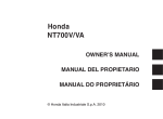
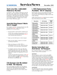
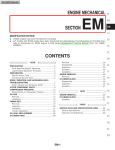
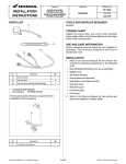
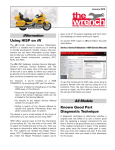
May 2010
iNformation
How to Use HISP
HISP (Honda Interactive Service Publications) is a
valuable tool that allows you to quickly find service information for a specific model.
HISP can be found in the Service Publications
drop-down menu, under the Service tab of iN. To
access HISP, logon to iN and follow this path:
If no folders appear, simply click on Search
and a list of subject-specific information links
will appear on the right. Click on the link to
view the information.
You’ll notice icons next to the information
links. These indicate where the information
comes from or what type of information it is.
Icon
Information Source or Type
Information
Owner’s Manual
Service >Service Publications >HISP (Service Manuals)
Specifications
HISP has information from the following sources:
Service Bulletin
• Service Manuals
• Owner’s Manuals
• Service Bulletins
• The Wrench newsletters
• DTC Troubleshooting procedures
There are two ways to access the information.
After entering either the unit VIN or model and
year, you can either (1) type in a keyword or (2)
select from three main subjects; Owner’s Manuals, DTC Troubleshooting, or Repair Procedures.
1. When using the keyword search, write the
term in the data field and click Search. A list of
results will appear on the right of the screen,
each item on the list is a link to information.
2. When using the Subjects option, select one of
the three subjects; Repair Procedures, DTC
Troubleshooting, or Owner’s Manuals.
Depending upon your selection, a set of System folders may appear. These folders open
to sub-folders allowing for a more refined
search. Select the desired folder/sub-folder
and click Search. A list of system-related links
will appear on the right. Click on a link to view
the information.
Service Manual procedure
The Wrench Technician’s Newsletter
If you just want to use the Service Manual, you
can use the digital version in a similar manner as a
printed copy. To access the Service Manual use
the following procedure:
1. Select Repair Procedures in the Select Subject drop-down
2. Select the General Information folder from the
Select System options
3. Click Search
4. Click on the Contents listing
This will give you the contents page of the Service
Manual from which you can reach any section of
the manual via links.
New iN Error Message
A new error message is being phased
into iN. Instead of a pop-up window, a
red circle and exclamation mark symbol
will appear next to the data field where
the error occurred. For information about the error
either click on the data field or pass your cursor
over the symbol.
ATV
2005-2009
TRX500FE/FPE/FM/FPM
C1 Gear Replacement
If you replace either the C1 gear or the reverse
and C1 gear shifter on a 2005-2009 TRX500FE/
FPE/FM/FPM, the new parts come as a set and
have a different number of engagement dogs (6)
than the originals.
TP SENSOR SUB-HARNESS
CONNECTOR
If water is present, the unit will likely come back in
the future with a DTC 4 (TPS circuit). The new
sub-harness will stop water from penetrating the
TP sensor but it won't stop corrosion of the connector terminals. When these terminals corrode,
the tension tang in the connector can break and
won’t allow the connector to make a complete circuit. A broken connector can easily be found with
the pin fit tool.
On-Road
REVERSE AND C1 GEAR
SHIFTER PUNCHMARKS
When installing the shifter, position it with the
punch-marked side facing the C1 gear.
2010 NT700V/A
Electrical Accessory
Installation
See the revised pages 12-16 and 12-18 of the
2005-2009 TRX500FE/FPE/FM/FPM/TM Service
Manual. The revised pages were sent to dealers in
October 2009.
2007 TRX500FE/FM
2007 TRX500FA/FGA
Wire Harness Drainage
Safety Recall
The following best practice was sent in by Jay
Barnett who is the Parts and Service Manager at
John’s Honda in Hot Springs, AR. Thanks Jay!
When installing the TP sensor sub-harness for the
2007 TRX500FE/FM and 2007 TRX500FA/FGA
Service Bulletin #3, it is very important to check
the condition of the connector.
When installing the accessory electrical socket kit
and/or the heated grip kit to your customer's
NT700V/A, you will need to order and install the
accessory sub-harness kit. This small sub-harness
connects the electrical accessories to the unit's
main wire harness.
To install the heated grips, you will also need the
heated grip attachment. See the list of related
accessories and part numbers in the table below.
Accessory
Part Number
Accessory Electrical Socket Kit
08V70-MCS-100
Grip Heater Kit
08T50-MEW-100
Heated Grip Attachment
08T49-MEW-100
Sub-Harness Kit
08A30-MEW-100
2010 VFR1200F/FD
2009 NSA700A DN-01
Wash Off that Coating
To protect the windscreen of the VFR1200F/FD
and DN-01, a light water-soluble film-type coating
was applied at the factory.
You can easily wash off this coating just using
warm soapy water and a clean, soft towel. If the
coating is stubborn, let it soak under a sponge.
PWC*
Non-Current PWC
Handling
Here follows some useful tips for preparing noncurrent AquaTrax models for showroom display
and customer delivery.
Storage of units
Per your Honda Sales Agreement, your PWC
inventory must be covered and dry. Units left in
direct sunlight may color fade. Deck mats may
peel up if the unit is stored in harsh conditions.
Faded body panels and seats make a PWC difficult to sell and are not warrantable.
Do not allow the foot wells to fill up with standing
water. Standing water can lead to blistered or
stained gel coat and peeling deck mats. These
problems reduce customer satisfaction and are
not warrantable.
Preparing units for display or delivery
• Wash the unit with mild soap and water.
• Dry the body and seat thoroughly.
• Apply Pro Honda Spray Cleaner Polish to all
painted surfaces.
• Do not activate the battery until the unit is ready
for customer delivery.
• Do not fill the fuel tank with fuel until the unit is
ready for customer delivery.
Taking care of the unexpected
Carefully inspect all PWC for transportation damage at the time of receipt. Follow transportation
claim guidelines for repairs and claim filing.
Most units will start within a few revolutions once
fresh fuel is added. Do not apply throttle during
startup as this may cause spark plug fouling.
If the unit fails to start after proper Set-Up and PDI
procedures:
1. Check the spark plugs for fouling. Replace any
fouled spark plugs.
2. If the spark plugs are okay, confirm that there
is proper fuel pressure. Troubleshoot any fuel
pressure issues as necessary.
3. If fuel pressure is good, troubleshoot for
clogged fuel injectors.
MUV*
2009-2010 MUV700 Big Red
MUV Inboard Joint
Information
If an inboard drive joint on a MUV700 Big Red
becomes dislodged from the differential housing,
there are a few things you’ll need to check and
care taken when ordering parts.
If the inner joint has become dislodged, inspect
for damage to the splines and the internal splines
they mesh into. If there is no damage to either, a
new circlip must be installed before reassembling.
Once in place, give the axle a firm tug to make
sure they are secure.
The right side front and rear inboard joints are the
same, but the left side front and rear joints are different. They have different shaft diameters, so the
circlips are different.
07LMJ-001000B
070MA-MEA0100
OR
07YMF-MCJA200
07YMF-MCJA300
07AMJ-HW1A100
07LMJ-001000A
070PZ-ZY30100
070PZ-ZY30100
AND
07AMZ-MEHA100
REVISION S430 JUNE 09 (DRW.1)
Item
Description
Left Front
Right Front
A
Front Inboard Joint
44230-HL1-A01
42220-HL1-A01
B
Circlip
44319-SR1-003
44319-SC2-003
07AMZ-MECA100
07YMF-MCJA400
07YMF-MCJA100
*THESE ITEMS INCLUDED WITH
07LMJ-001030A
07LMJ-001000B
OR
07LMJ-001000A
C
Inboard Band (Large)
42337-HP7-A01
42337-HP7-A01
D
Snap Ring
90653-HP7-A01
90653-HP7-A01
E
Stopper Ring
42231-HP7-A01
42231-HP7-A01
(QTY 4 HOSES & 4 ADAPTERS)
(PICTURE NOT TO SCALE)
07GMA-KT80110
OR
07908-4600200
07GMA-ML70110
07908-4220100
07LMJ-001010B
OR
07LMJ-001010A
07LMJ-001020B
OR
07LMJ-001020A
07908-3230000
A
B
07GMA-KT80120
E
INSPECTION / ADJUSTMENT I
New inboard joints do not include the circlips, so
make sure to order them separately. Refer to the
chart below for a quick reference.
07GMA-ML70120
C
07AMJ-HW3A100
REVISION S429 SEPT. 08 (DRW. 1)
A)07AMJ-HW3A300
B)07AAJ-S6MA200
07AAJ-S6MA200(B)
C)07AAJ-S6MA300
(MALE)
Item
Description
Left Rear
Right Rear
REVISION S429 SEPT. 08 (DRW. 1)
07401-0010000
A)07AMJ-HW3A200
B)07AAJ-S6MA400
C)07AAJ-S6MA500
07AAJ-S6MA400(B)
(FEMALE)
07AMJ-MEWA100
A
Rear Inboard Joint
42230-HL1-A01
42220-HL1-A01
B
Circlip
44319-SR1-003
44319-SC2-003
C
Inboard Band (Large)
44316-SC2-013
42337-HP7-A01
D
Snap Ring
90653-HP7-A01
90653-HP7-A01
E
Rear Inboard Joint
42230-HL1-A01
42220-HL1-A01
The Tool Chest
Check your Tools
In preparation for the upcoming busy season,
now’s the time to inventory and organize your
tools, check your dealership’s compliance with
the American Honda minimum tool and equipment requirements, and to check your Special
Tools cabinets and board for missing tools.
You’ll want to be able to quickly and correctly service and repair your customers’ units, so review
the following Special Tool News (STN) Service
Bulletins and order whatever tools are missing.
ATV STN #1: Honda ATV Dealers Minimum Tool
and Equipment Requirements
STN #1: Honda ATV, Motorcycle, Scooter, and
PWC Dealers Minimum Tool and Equipment
Requirements
STN #24: Special Tool Cabinet and Board Layout
References
DRAWER #1 INSPECTION / ADJUSTMENT I
C 2006 AMERICAN HONDA MOTOR CO., INC. ALL RIGHTS RESERVED.
OCT. 2006–M
DRAWER #1
D
An increasingly important service tool listed in
STN #1 is a computer. As Service Bulletins, SetUp Instructions, and other important service information are only available on iN, American Honda
requires a computer in every dealer’s service area.
The minimum computer requirements can be
found on iN by going to:
iN Support > iN Minimum Requirements
Service Publications
Required Service
Manuals
All dealers are required to have Service Manuals
for all models they are authorized to sell and service for the most recent five model years (current
and previous four). Currently that is manuals for
2006-2010 model years.
Honda also highly recommends having Service
Manuals for the previous five model years as well.
Currently that includes manuals for 2001-2005.
To order Service Manuals from iN follow this path:
Business Management > eMall > and click on
Helm under Service Publications.
THE WRENCH
©2010 American Honda Motor Co., Inc. All Rights Reserved. Published by: AHM Motorcycle Service Communications, 1919 Torrance Blvd., Torrance, CA 90501.
All suggestions become the property of American Honda Motor Co., Inc. Sending a suggestion gives American Honda permission to publish it without further
consideration. *The information in this article is for authorized Honda PWC or MUV dealers only (applicable only if a PWC or MUV article is included in the issue).
Editor: Carl Pulley
E-mail The Wrench at [email protected]
MSN 13243 (1004)