1
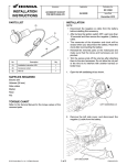
Accessory
INSTALLATION
INSTRUCTIONS
Application
MII 14948
BACK UP ALARM
P/N 08V70-HL5-A00
BACK UP ALARM HARNESS
P/N 08V71-HL5-A00
PARTS LIST
Publication No.
SXS500M2
Issue Date
July 2014
TOOLS AND SUPPLIES REQUIRED
(1)
Scissors
TORQUE CHART
Tighten all screws bolts, and nuts to their specified
torque values. Refer to the Service Manual for the torque
values of the removed parts.
(2)
USE AND CARE INFORMATION
Check accessory mounts frequently and retighten if
necessary. Trim all excess material on wire ties no
shorter than 5 mm.
(3)
INSTALLATION
1.
No.
Description
•
•
•
•
•
•
•
•
•
2.
Qty
(1)
Back up alarm
1
(2)
Wire tie short
14
(3)
Back up alarm harness (sold separately)
1
ACCESSORY SUB-HARNESS
Sold separately
P/N 08Z08-HL5-A00
The Accessory Sub-Harness is required for the
installation of this accessory.
Refer to the Service Manual for the vehicle and
remove the following components in the following
order:
Rear fender/carrier/center cover as an assembly.
Battery cover
Air cleaner housing
Seat (cushion and backrest)
Seat bottom cover (right and left)
Seat rear cover
Rear floor cover
Front floor plate
Front hood
Refer to the Service Manual for the vehicle and
disconnect negative (-) battery cable.
(1)
No.
(1)
Description
Accessory sub-harness
© 2014 Honda Motor Co., Ltd. - All Rights Reserved.
Qty
1
1 of 6
08V70-HL5-A00 & 08V71-HL5-A00
3.
Install and connect the back up alarm harness between the two halves of the gear position switch connector as
shown.
Back up alarm harness connection:
BACK UP ALARM
HARNESS
MAIN HARNESS
TO ALARM BUZZER
GEAR POSITION SWITCH 8P (Gray)
CONNECTOR (Harness side)
GEAR POSITION SWITCH 8P (Gray)
CONNECTOR
Release from its mounting clip and then disconnect.
BACK UP ALARM HARNESS
CONNECTOR TO GEAR
POSITION SWITCH
CONNECTOR (Engine Side)
Secure connector body to
panel with the clip.
GEAR POSITION
SWITCH CONNECTOR
(HARNESS SIDE)
BACK UP ALARM
BUZZER
BACK UP ALARM
HARNESS
ACCESSORY
SUB-HARNESS
(Sold separately.)
GEAR POSITION
SWITCH CONNECTOR
(ENGINE SIDE)
2 of 6
4.
Follow the main harness down. Secure the back up alarm harness to the main harness with wire ties near the back
of the engine, under the passenger seat as shown.
NOTE:
Secure the alarm harness only to the main harness. Do not wire tie any control cables.
BACK UP
ALARM HARNESS
FUEL TANK
MAIN HARNESS
WIRE TIE
WIR
WIRE TIE
ENGINE
MAIN HARNESS
3 of 6
5.
Follow the main harness going up. Secure the back up alarm harness to the main harness with wire ties along the
front right side of the vehicle as shown.
RIGHT HEADLIGHT
MAIN HARNESS/BACK UP ALARM HARNESS
WIRE TIE
FRONT
SHOCK ABSORBER
6.
Locate the DLC (4P Red) connector and remove the dummy cap. Be sure to leave the black tape around the
connector body (harness side).
<VIEW UNDER FRONT HOOD>
DLC (4P Red) CONNECTOR
4 of 6
7.
Connect the accessory sub-harness to the DLC (4P Red) connector.
Connect the back up alarm harness to the red tape wire of the accessory sub-harness as shown.
• Note that only one connector of the accessory sub-harness is used for the back up alarm, the remaining
connectors are for other accessories.
Secure any excess harness to the frame with wire ties.
<VIEW UNDER FRONT HOOD>
ACCESSORY
SUB-HARNESS
BACK UP ALARM
HARNESS
MAIN HARNESS
WIRE TIE
DLC (Main harness)
RED TAPE
HORN
BACK UP ALARM
WORK LIGHT/
LED LIGHT
WINCH
ACCESSORY SU
S
SUB-HARNESS
B HARNESS
5 of 6
8.
Install the back up alarm buzzer to the location shown:
Back up alarm buzzer installation:
8 mm FLANGE
G BOLT
Reinstall.
ALARM BUZZER
FRAME
8 mm FLANGE BOLT
Remove.
9. Connect the back up alarm buzzer connector to the back up alarm harness.
10. Reconnect the negative (-) battery cable.
11. Start the engine and then select reverse to confirm the performance of the back up alarm.
• Troubleshoot any problems if necessary.
12. Refer to the Service Manual, reinstall the removed vehicle parts in the reverse order of removal.
6 of 6