1
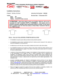
BAER Your Complete Performance Brake Supplier! Installation Instructions Product: Pro+, Ext + Rear Instruction Part Number: 6000385 Vehicle Revision Date: 14 August 2013 Make: GM Model: 10/12 Bolt Axle with Bearings in Housing Year(s): All ATTENTION: Read this before going any farther! Returns will not be accepted for ANY installed PART or ASSEMBLY. Use great care to prevent cosmetic damage when performing wheel fit check. In the event that a product must be returned, please contact Baer Customer Service for a RMA Number. Notices – Read and Follow BEFORE ATTEMPTING INSTALLATION All installations require proper safety procedures and protective eyewear. All installations assume basic mechanical skill and a factory service manual for the vehicle on which the installation is to be performed. All references to the “left” side of the vehicle correlate to the driver’s side of the vehicle. Any installation requiring you to remove a wheel or gain access under the vehicle requires use of jack stands appropriate to the weight of the vehicle. In all cases, jack stands rated for a minimum of 2-tons is recommended. A selection of hand tools sufficient to engage in the installation of these products is assumed, and is the responsibility of the installer to have in his/her possession prior to beginning this installation. All installations, which require removal of hydraulic hoses and/or bleeding of the brakes, require appropriate fitting/line wrenches, safety catch can, and protective eyewear. Other than these items, if unique or special tools are required they will be stated appropriately in the installation step. ALWAYS CONFIRM WHEEL FIT PRIOR TO BEGINNING INSTALLATION OF ANY BRAKE SYSTEM OR “UPSIZED” ROTOR UPGRADE! In addition to checking wheel fitment (available online at www.baer.com), always place the actual corner assembly or a combination of the caliper assembly onto the rotor, and into the actual wheel. This procedure will reconfirm proper clearance between the caliper and the wheel before proceeding with the actual installation. Returns will not be accepted for systems that have been partially or completely installed. Use extreme care when checking wheel fitment to prevent any cosmetic damage. Baer Brakes Inc. 2222 W. Peoria Ave. Phoenix, Arizona 85029 Ph. (602) 233-1411 Fax. (602) 352-8445 Email. [email protected] www.baer.com Page 1 of 10 BAER Your Complete Performance Brake Supplier! When installing rotors on any Baer Products be sure to follow the direction of rotation indicated on the rotor hat area with either an arrow, or an “L” for left, or an “R” for right, or both. “L” or left always indicates the driver’s side of US spec vehicles. Images shown are “L” left rotors: A proper professional wheel alignment is required for any system requiring replacement of the front spindles, or tie rod ends. Follow factory prescribed procedures and specifications unless otherwise indicated. At all times stop the installation if anything is unclear, or the parts require force to install. Consult directly with Baer Technical Staff in such instances to confirm details. Please have these instructions, as well as the part number machined on the component that is proving difficult to install, as well as the make, model, and year (date of vehicle production is preferred) of your vehicle available when you call. Baer’s Tech Staff is available from 8:30-am to 5-pm Mountain Standard Time (Arizona does not observe Daylight Savings Time) at 602 233-1411 Monday through Friday. Baer Brakes Inc. 2222 W. Peoria Ave. Phoenix, Arizona 85029 Ph. (602) 233-1411 Fax. (602) 352-8445 Email. [email protected] www.baer.com Page 2 of 10 BAER Your Complete Performance Brake Supplier! INSTALLATION: 1. Support the vehicle with properly rated jack stands and remove the rear wheels. Place a drain pan under the differential and remove the cover. 2. Remove the drums. Sometimes the drums will adhere to the axles from rust. If this is the case, tapping on the outer edge of the drum with a hammer will shock this loose and allow removal of the drum. 3. Remove the differential pin lock bolt from the carrier (photo 1). Most GM vehicles use a 5/16” or ½” bolt head. It is best to use a 6 point wrench on this as it may be very tight. 4. Remove the axles, taking care not to damage the seals. This is a good time to inspect the seals, axles and bearings, replacing as necessary. Also, measure the outside diameter of the axle flange. To properly seat in the rotor, the flange diameter cannot exceed 5.9”. If yours is larger, a machine shop can turn these down for proper fit. Axle flange diameter for 71-76 GM Full Size model years: The outside diameter of the axle flange must be no greater than 7.0” in order to properly fit inside of the rotor hat. If yours is larger, a machine shop can turn these down for proper fit. Baer Brakes Inc. 2222 W. Peoria Ave. Phoenix, Arizona 85029 Ph. (602) 233-1411 Fax. (602) 352-8445 Email. [email protected] www.baer.com Page 3 of 10 BAER Your Complete Performance Brake Supplier! 5. Disconnect the fluid lines from the backing plate and cap with supplied vinyl caps. Leaving all drum brake components attached, remove the entire brake backing plate. Save the fasteners as these will be reused for the new bracket/park brake assembly. Disengage the park cable from the frame and front primary cable. The Baer cable, if supplied, will attach to the frame and primary cable just as the OE unit did. Flange housing hardware for 71-76 GM Full Size model years: New fasteners were sent with your new brake system to replace the eight (four per side) previous OE fasteners. The components are listed below: (8) 7/16-20x1.25” Socket head bolts (8) 7/16” washers (8) 7/16”-20 Nylock nuts Photo shown of OE fasteners and OE backing plate (Driver’s side) Baer Brakes Inc. 2222 W. Peoria Ave. Phoenix, Arizona 85029 Ph. (602) 233-1411 Fax. (602) 352-8445 Email. [email protected] www.baer.com Page 4 of 10 BAER Your Complete Performance Brake Supplier! 6. Install the new bracket/park brake assembly using the original fasteners that secured your brake backing plate (for 71-76 GM models use the new hardware supplied – listed in Step 5). These are left and right specific, the left (driver’s side) carries a part number engraved beginning with the numbers 671, and the right side will begin with the numbers 672. The park shoe actuator will be at the bottom, the retainer at the top. Torque the fasteners to 45 ft∙lbs. See photos on continued page for reference: Bracket/park brake assembly install for 71-76 GM Full Size model years: Install the new bracket/park brake assembly using the supplied 7/16-20x1.25” Socket head bolts, washers, and Nylock nuts. The bolts will enter from the outboard side of the new bracket/park brake assembly, to the inboard side. Secure the bolts with the supplied washers and Nylock nuts (washers and nuts will secure to the inboard side of the flange housing). Torque all bolts to 78 ft∙lbs. Baer Brakes Inc. 2222 W. Peoria Ave. Phoenix, Arizona 85029 Ph. (602) 233-1411 Fax. (602) 352-8445 Email. [email protected] www.baer.com Page 5 of 10 BAER Your Complete Performance Brake Supplier! Park brake assembly correctly installed Park assembly installed on driver’s side Baer Brakes Inc. 2222 W. Peoria Ave. Phoenix, Arizona 85029 Ph. (602) 233-1411 Fax. (602) 352-8445 Email. [email protected] www.baer.com Page 6 of 10 BAER Your Complete Performance Brake Supplier! 7. Repeat these procedures for the other side. 8. Install axles, c-clips, differential pin, and retaining bolt. Install the cover and refill with proper gear lube. 9. Install the rotors on the correct sides and retain with three lug nuts and washers to avoid scratching the rotor hat. 10. The caliper can be mounted in two positions: behind the axle centerline or on centerline. Choose the best location for your application and install the intermediate bracket. This is supplied with Stainless Steel slide pins to allow the intermediate bracket and caliper to move with the axle on C-clip style axles. The part number engraved on the bracket will face outboard. Tighten the bolts for now as shimming will need to occur. Bracket in rear, upper position Bracket in forward position Baer Brakes Inc. 2222 W. Peoria Ave. Phoenix, Arizona 85029 Ph. (602) 233-1411 Fax. (602) 352-8445 Email. [email protected] www.baer.com Page 7 of 10 BAER Your Complete Performance Brake Supplier! Rear view of 6P Caliper installed on intermediate bracket 11. With pads removed, install the correct side caliper onto the intermediate bracket (bleeder screws point upward). Pro+ systems use Socket head bolts. Extreme+ systems contain ARP studs with 12 point nuts. Tighten the bolts for now as shimming will need to occur. Shimming Procedure Baer Brakes Inc. 2222 W. Peoria Ave. Phoenix, Arizona 85029 Ph. (602) 233-1411 Fax. (602) 352-8445 Email. [email protected] www.baer.com Page 8 of 10 BAER Your Complete Performance Brake Supplier! Shimming Procedure Slide the caliper towards the outboard side of the vehicle (along the centerline of the spinde), as far as it goes, until it touches the rotor face. Note: This process for shimming is preferred without the brake pads installed, but is not required. Measure the gap from the rotor to caliper body at 4 points, top inside and outside, bottom inside and outside. Write down all measurements. Subtract the top inside measurement from top outside. This will require a shim at the top bracket bolt equal to half of this difference to center the caliper. For instance, inside measurement of .865”, outside of .905” has a difference of .040 which would require a .020” shim installed to center. Do the same with the bottom measurements to center this also. This may require different thickness shims top and bottom. Procedure 1. Select the required shims from the kit provided 2. Remove the caliper 3. Loosen the bolts connecting the intermediate bracket to the park brake assembly 4. Install the appropriate shims (between the slider pin heads and bracket/park brake assembly), removing one bolt at a time, and snug the same bolts for fit check 5. Reinstall the caliper and recheck gap measurements. Continue adding shims until the caliper does not touch the rotor when moved from side to side while bolted to the bracket. This gap between the rotor and the caliper should be within 0.010” on both sides 6. Re-shim if necessary. When proper shimming has been achieved, torque the M12-1.75x45 bolts to 85 ft∙lbs. Finally, torque the caliper bolts to 75 ft∙lbs. Location of shims Baer Brakes Inc. 2222 W. Peoria Ave. Phoenix, Arizona 85029 Ph. (602) 233-1411 Fax. (602) 352-8445 Email. [email protected] www.baer.com Page 9 of 10 BAER Your Complete Performance Brake Supplier! 12. A CSV (centering stabilizer valve) will be attached to your caliper. This helps to keep the caliper properly centered over the rotor. Attach the banjo bolt to the hose and into the valve using copper washers on either side of the banjo fitting. Install the Hardline retainer assembly, bending the original hardline to fit into the bracket provided with this set. Attach the hardline to the steel braided hose and install the hose lock provided. **IMPORTANT: Ensure to route the brake hose away from suspension and wheels to avoid any interference through full articulation of suspension system. Tighten all banjo bolts, and hose adaptors to 10-15 ft∙lbs. CSV attached to rear of 6P Caliper CSV (side view) 13. Install park cables first into the caliper, then to frame, and finally, connect to the primary cable. 14. Double check all attachment points and fluid connections. Refer to Bleeding, and Pad Bedding & Rotor Seasoning Procedures contained on a separate sheet, or on www.baer.com For service components and replacement parts contact your Baer Brake Systems Tech Representative. Baer Brakes Inc. 2222 W. Peoria Ave. Phoenix, Arizona 85029 Ph. (602) 233-1411 Fax. (602) 352-8445 Email. [email protected] www.baer.com Page 10 of 10