1
4. Apply light oil onto the threads of the Adjustment Screw. Small amounts of air leakage in the adjustment
hardware may be present during operation. This is a normal operating condition. Thread the Adjustment
Screw by hand until a slight tension is felt, this position is the minimum pressure setting. Do not tighten screw
any further. Pressure is to be adjusted later in these instructions. Install the Flat Washer, then the Jam Nut.
Tighten the Jam Nut hand tight for later adjustment.
5. Install Bracket to regulator using supplied Bracket Screws and Bracket Lock Washers. Tighten Bracket Screws
between 25-40 in·oz of torque (snug, do not over tighten screws).
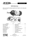
6. Install the fuel fittings (not supplied). The threads used on these Fuel Ports are not tapered or pipe threads.
Do not use Teflon® thread tape or thread sealant on these threads, as this can cause leakage or introduce
debris into the fuel system. Fittings to be used with these style of ports require use of the enclosed–906 Orings for proper sealing (reference diagrams, below). Use light oil to lubricate the O-rings just prior to
installation. Install the O-rings onto the fuel fitting first. Position the O-ring in the thread relief of the fitting as
shown in the diagram, below. Thread fitting into regulator and tighten between 5 and 15 ft·lbs of torque.
7. Use Teflon® tape or thread sealant on all 1/8”-NPT fittings to be used for the Gauge Port and Pressure
Reference Port (see diagrams, below). Install fittings or plug as required. If pressure reference port is not
plumbed to the intake manifold (for typical EFI applications, port is plumbed to the intake manifold) then install
the Barbed Fitting (supplied) and allow fitting to vent to atmosphere (do not plumb or plug port).
8. Install regulator assembly into vehicle, fastening the bracket to the vehicle. Attach fuel lines, Gauge Port line (if
external pressure gauge is used in application) and Pressure Reference Port line (if applicable). Boosted
applications (such as turbo or supercharger) will require a hose clamp on barbed fitting to prevent hose from
coming loose. Use of –3AN or –4AN fitting and line can also be used as a substitute to the barbed fitting.
Adjustment
Screw
Spring Guide Ball may appear to be Off-Center.
Adjustment Screw Centers this Part upon Installation.
Install with Cup
toward Regulator
Front
(Logo)
Jam Nut
Gauge Port Plug
(can be substitued
for gauge fitting)
-6AN Inlet Port
(on each side)
1/8"-NPT Pressure
Reference Port
(Engine Vacuum
Typically, for EFI)
Flat Washer
Unique Serial
Number
Identification
(1/8") Barbed Fitting
(can be substituted
with other fitting)
Example -6AN
Union Fitting Shown
(Not Supplied)
Example -6AN
Union Fitting Shown
(Not Supplied)
-906 O-ring Shown,
Prior to Fitting
installation
1/8"-NPT Gauge Port
-6AN Return Line Port
-906 O-ring
Example -6AN
Union Fitting Shown
(Not Supplied)
(3x) Bracket Lock Washer
(3x) Bracket Screw
9. Inspect fuel system for any contact of fuel lines or wires with other components that can cause chafing or
rubbing. Secure all components and fuel lines.
10. Connect the vehicle’s battery. Turn on fuel pump (typically by bypassing fuel pump relay) without engine
operating. ECU or engine management computer may be controlling the relay. The ECU may only operate
pump for a few seconds each time ignition switch is set to on. The pump will have to operate several seconds
(30+) to prime and drive air out of the fuel system. Fuel system pressure should read about 25 PSIG (use an
external gauge for adjustment if a permanent gauge is not used). Inspect vehicle for any leaks. Turn off fuel
system and repair any leaks that may be present before continuing.
11. When adjusting pressure, be sure that fuel pump is operating to monitor pressure. Increase pressure by
rotating adjustment clockwise. Do not thread Adjustment Screw past jam nut within 1/8”. Over tightening the
adjustment screw can damage the regulator. It is recommended to use a “baseline” pressure reference when
adjusting the pressure (adjusting the pressure with engine off or Pressure Reference Line unhooked). The
vehicle’s engine may not produce consistent vacuum during idle to have repeatable readings.
12. After final adjustment of fuel pressure, tighten Jam Nut. Road test vehicle, and retest pressure upon return to
ensure accurate adjustment.
105020121-1, Rev A
Sheet 3 of 4