1
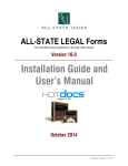
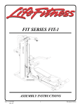
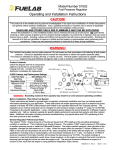
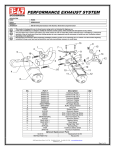
COMPLETE CHASSIS FUEL LINE KITS
For 1996-2000 Honda Civic Equipped with B-Series Engine
Catalog #641560, 641563
INSTALLATION INSTRUCTIONS
PLEASE study these instructions carefully before beginning this installation. Most installations can be accomplished with common tools and
procedures. However, you should be familiar with and comfortable working on your vehicle. If you do not feel comfortable performing this installation,
it is recommended to have the installation completed by a qualified mechanic. If you have any questions, please call our Technical Hotline at:
1-800-416-8628, 7:00 am - 5:00 pm, Pacific Standard Time, Monday through Friday or e-mail us at [email protected].
IMPORTANT NOTE: Proper installation is the responsibility of the installer. Improper installation
will void your warranty and may result in poor performance and engine or vehicle damage.
DESCRIPTION: This Russell Performance Complete Fuel Line kit includes all necessary parts to replace your factory fuel system with a high flow, high
performance fuel pump, fuel lines, fuel filter, fuel rail and fuel pressure regulator, while retaining the factory fuel tank. These kits feature a high
performance Edelbrock in-tank fuel pump, Edelbrock aluminum fuel rail, Edelbrock Adjustable Fuel Pressure Regulator, Russell Fuel Filter, Russell
Proflex or Proclassic hoses, and Russell AN fittings. The kit is designed to fit 1996-2000 Honda Civic chassis equipped with a Honda DOHC B-Series
engine, and will provide increased fuel flow for high performance applications. Kit #641560 features Proflex hoses and red and blue anodized fittings,
while kit #641563 features Proclassic hose and fittings with a black and clear finish.
KIT CONTENTS:
❑ 1
❑ 1
❑ 1
❑ 1
❑ 1
❑ 16ft
❑ 14ft
❑ 3
❑ 1
❑ 2
❑ 1
❑ 1
Fuel Rail. High Flow, Honda B-Series Engines (PN 4796)
Adjustable Fuel Pressure Regulator (PN 1728)
In-Tank Fuel Pump, 255 Liters/Hour (PN 17937)
Inline Fuel Filter, 10 Micron, -10AN In/Out
Inline Fuel Filter Mounting Clamp
Proflex/Proclassic Braided Stainless Steel Hose (-6AN)
Proflex/Proclassic Braided Stainless Steel Hose (-4AN)
Straight Hose End (-6AN)
Straight Hose End (-4AN)
90° Swivel Hose End (-6AN)
45° Swivel Hose End (-6AN)
8mm Fuel Tank Outlet to -6AN EFI Adapter Fitting
TOOLS REQUIRED:
❑
❑
❑
❑
❑
Hand Tools, Standard and Metric
Standard and Metric Allen Keys
Phillips Screwdriver
Wire Stripping and Crimping Tool
Pliers
❑
❑
❑
❑
❑
❑
❑
❑
❑
❑
❑
❑
❑
❑
❑
❑
❑
2
2
2
1
1
1
2
1
10
10
12
1
1
-10AN to -6AN Adapter Fittings (with o-rings)
-8AN to -6AN Adapter Fittings (with o-rings)
-6AN Dry-Sump Fittings (with o-rings)
-6AN Block-Off Plug (with o-ring)
-6AN Female to -4AN Male Coupling
-6AN Female Coupling Nut
#4 Hose Clamp Cover (Chrome/Red Anodized)
#4 Hose Clamp
#4 Cushion Clamp
#6 Cushion Clamp
Tie-Wraps
Russell Assembly Lube/Sealant
Fuel Pressure Gauge
AN Wrenches
AN Fitting Assembly Lubricant
Fuel Pressure Gauge (For Fuel Pressure Adjustment)
Mounting Hardware for Regulator & Filter Bracket
BEFORE BEGINNING INSTALLATION
WARNING: EXPOSED FUEL AND OIL WILL BE PRESENT DURING THIS INSTALLATION. WHEN WORKING AROUND
GASOLINE OR OIL, ALWAYS WORK IN A WELL VENTILATED AREA, AND KEEP ALL OPEN FLAMES, SPARKS, AND OTHER
SOURCES OF IGNITION AWAY FROM THE WORK AREA. FAILURE TO DO SO CAN RESULT IN A FIRE OR EXPLOSION.
MAKE SURE TO DISCONNECT YOUR BATTERY TO AVOID THE POTENTIAL FOR SPARKS IN THE WORK AREA!
NOTE: Certain Honda vehicles have security protected audio systems. If your vehicle is equipped with a factory audio system, be
sure to have the security code written down prior to disconnecting the battery. See Honda Service Manual for additional details.
WARNING: SOME PROCEDURES IN THIS INSTALLATION WILL REQUIRE THE VEHICLE TO BE RAISED ON JACKSTANDS OR A LIFT. WHEN
RAISING A VEHICLE, MAKE SURE THE VEHICLE IS ON LEVEL GROUND AND SUPPORTED SECURELY BY JACKSTANDS.
NEVER WORK UNDER A VEHICLE THAT IS SUPPORTED BY A JACK ONLY!
Catalog #641560, 641563
Rev. 10/07 - AJ/mc
Page 1
©2007 Edelbrock Corporation
Brochure #63-641560
BEFORE BEGINNING INSTALLATION (Continued)
BEFORE BEGINNING: Someone who has a basic knowledge of automobile repair and modification and is familiar with and comfortable with working
on their vehicle can accomplish the mechanical installation of this kit using common tools and procedures. However, this kit is designed to allow you
to custom fit the fuel lines to your application, and will require that you cut hoses to fit and drill holes for Fuel Pressure Regulator mounting. If you do
not feel comfortable with any of the steps listed below, please consult a qualified professional installer. Make sure to read the instructions provided
with the supplied fuel rail and fuel pressure regulator. These will be referenced throughout this instruction sheet.
AFTER INSTALLATION, BEFORE STARTING THE VEHICLE: ALWAYS make sure to check for any leaks BEFORE starting the vehicle. Reconnect the
battery and turn the ignition key to the “on” position. This will activate the fuel pump and pressurize the fuel system. If any leaks are present, turn
the ignition “off”, disconnect the battery, and make the necessary corrections before continuing.
INSTALLATION PROCEDURE
UNDERHOOD DISASSEMBLY AND FUEL RAIL INSTALLATION
1.
Make sure the vehicle is on level ground, and the gear selector is in
“Park” or in 1st gear. Set the parking brake or chock the wheels.
2.
Disconnect the battery negative terminal (See note on page 1
regarding Honda/Acura security protected audio systems).
3.
Thoroughly clean the area surrounding the fuel injectors and the fuel
rail. This will prevent debris from entering the fuel system or the
intake manifold upon fuel rail removal.
4.
Relieve any residual fuel pressure in the fuel system. Remove the
fuel filler cap, then relieve fuel pressure by loosening the banjo bolt
connecting the fuel line to the fuel filter. Place a shop towel or rag
over the wrench while loosening the banjo to soak up any fuel spray
(See Fig. 1). When loosening or tightening the banjo bolt on the
fuel filter can, use a 19mm wrench on the hex of the fuel filter can
to counteract the torque of loosening or tightening the banjo bolt.
This will prevent the fuel filter can and bracket from being
improperly loaded during loosening or tightening at the banjo bolt.
If your vehicle has a special banjo bolt at the fuel filter, which has a
service bolt in the top of the banjo bolt, use a box end wrench to
loosen the service bolt at the fuel filter while holding the banjo bolt
with another wrench. Keep the banjo or service bolt loose until all
pressure is relieved.
7.
Disconnect the wiring harness from the fuel injectors and from the
fuel rail. If your vehicle is equipped with a purge valve, disconnect
the wiring from the purge valve.
8.
Remove the vacuum line from the factory fuel pressure regulator.
Refer to the instructions supplied with the 4796 fuel rail, and remove
the fuel rail, factory fuel pressure regulator, supply line, and return
line from the vehicle as one assembly. Use care when separating
the fuel rail from the fuel injectors.
9.
Install the supplied -8AN to -6AN Adapter Fittings (with o-rings) into
the fuel rail using a bit of o-ring lube on the o-rings. Install the 1/8
NPT pipe plugs (supplied with fuel rail) if the gauge ports are not
being used (see fuel rail instructions).
10. Inspect the injectors and transfer them to the new fuel rail as
described in the fuel rail instructions.
11. Install the fuel rail / injector assembly on the intake manifold as
shown in the fuel rail instructions.
Adjusting Screw.
Locknut and Washer
Vacuum
Fitting
-6 AN Block
Off Plug
Figure 1
5.
6.
Remove the banjo bolt from the fuel filter and disconnect the fuel
supply line from the fuel filter. Using a small, fuel safe container,
allow the excess fuel to drain from the fuel line and fuel rail.
Disconnect the factory fuel return line from the steel tubing on the
firewall. Use rags or a small, fuel safe container to catch any spills.
Catalog #641560, 641563
Rev. 10/07 - AJ/mc
Page 2
-6 AN DrySump Fittings
Figure 2 - Fuel Pressure Regulator Fitting Placement
©2007 Edelbrock Corporation
Brochure #63-641560
FUEL PRESSURE REGULATOR MOUNTING:
1.
2.
3.
6.
Install the provided fittings into the fuel pressure regulator (See Fig.
2). Install one -6AN Dry Sump Union in the inlet port and one in the
return port (located at the bottom of the regulator). Install the -6AN
block off plug in the fuel outlet port of the regulator. Slip the -6AN
Female coupling nut over the -6AN female to -4AN male coupling.
Install this assembly over the -6AN dry-sump fitting previously
installed in the return port of the regulator. Install the vacuum fitting
supplied with the regulator in the port on the top half of the
regulator. Install the pressure adjusting screw and jam nut at the
top of the regulator. See the instructions provided with the regulator
for more information.
Install the factory fuel pressure regulator vacuum line onto the fitting
on the fuel pressure regulator. You may need to replace or extend
this line, depending on where you are mounting the regulator.
FUEL TANK PREPARATION AND FUEL PUMP INSTALLATION:
WARNING: PROCEDURES IN THIS SECTION WILL REQUIRE
THE VEHICLE TO BE RAISED ON JACKSTANDS OR A LIFT.
WHEN RAISING A VEHICLE, MAKE SURE THE VEHICLE IS ON
LEVEL GROUND AND SUPPORTED SECURELY BY JACKSTANDS. NEVER WORK UNDER A VEHICLE THAT IS
SUPPORTED BY A JACK ONLY!
1.
Determine a location in the engine compartment to mount the fuel
pressure regulator. Make sure it is in a location that will provide
clearance to route the -4AN return line to the regulator, and that you
will be able to easily connect a length of -6AN hose between the fuel
rail and the regulator. We chose a location on the firewall.
Fuel Tank Removal:
A.
Remove the rear seat cushion to provide access to the top
of the fuel tank and fuel pump access panel.
B.
Clean any dirt and debris away from the area and remove
the fuel pump access panel (See Fig. 5).
To mount the regulator in this location you will need to remove the
cowl cover (See Fig 3).
Figure 5 - Fuel Pump Access Cover Removed
C.
Disconnect the electrical connectors from the top of the
fuel level sender and fuel pump assembly (See Fig. 5).
D.
Disconnect the fuel supply line from the top of the fuel
pump assembly. Use pliers to remove the hose clamp
from the fuel return hose and remove the return line. Use
rags to absorb any fuel spillage.
E.
Raise the vehicle and drain the fuel tank of any remaining
fuel. Loosen the drain plug and drain fuel into clean, fuel
safe containers. Tighten the drain plug when empty.
F.
Remove the section of exhaust pipe that runs partially
below the fuel tank (See Fig. 6).
Figure 3 - Cowl Cover Removed
4.
5.
Following the instructions provided with the fuel pressure regulator,
use the provided bracket, and mark the location to drill the mounting
holes.
Mount the fuel pressure regulator to the bracket, and the
regulator/bracket assembly to the firewall (See Fig. 4).
NOTE: You may need to bend/modify the supplied bracket in
order to mount the fuel pressure regulator in your desired
location.
Figure 6 - Exhaust Midpipe Removal
Figure 4 - Regulator Mounted on Firewall
Catalog #641560, 641563
Rev. 10/07 - AJ/mc
Page 3
©2007 Edelbrock Corporation
Brochure #63-641560
F.
Remove the driver side rear tire to gain access to the fuel
fill tube cover. Remove the fuel fill tube cover (See Fig.
7A and 7B) and disconnect the fuel fill tube at the fuel
tank.
2.
3.
Fuel Pump Assembly Removal:
A.
Thoroughly clean all dirt and debris from the top of the fuel
tank. Clean out any dirt from around the fuel pump
assembly and retaining nuts. This must be done to
prevent dirt or foreign material from falling into the fuel
tank upon removal of the fuel pump assembly.
B.
Remove the fuel pump assembly mounting nuts and
carefully remove the assembly from the fuel tank.
C.
Set fuel pump assembly aside.
Fuel Pump Replacement:
A.
The electrical connections from the pump assembly to the
pump itself, may attach in one of two ways. There may be
a snap fit, plug type connector, or there may be ring
terminals attached to the pump with screws and nuts.
Disconnect the electrical connections from the pump; be
sure to note the polarity of the wires.
B.
Many vehicle pump supports have a L-shaped bracket
that is attached to the pump support with a screw and a
lockwasher. Loosening the screw and removing the pump
support allows the fuel hose to be removed from the pump
body, and for the pump to be removed from the bracket
easily. If the pump support and L-shaped bracket are
separate, remove the screw, and remove the pump
support, pump, fuel hose, and fuel clamps from the
bracket (See Fig. 9). If they are not separate, cut the fuel
hose and remove the clamps, fuel hose pieces, and fuel
pump from the pump support.
Figure 7A - Fill Tube Cover
Figure 7B - Fill Tube Cover Removed
G.
Carefully remove the tank support straps while supporting
the tank with a jack or a helper. Use caution, as some fuel
will be remaining in the fuel tank.
H.
Lower the tank slightly and disconnect the fuel tank vent
hose (See Fig. 8).
Figure 9 - Fuel Pump Support Bracket
C.
Install the new fuel filter onto the pump. Secure the filter
to the pump by pressing the retainer onto the center post
of the pump (See Fig. 10). Some applications may
require placing the pump into the pump support before
installing the filter.
Figure 8 - Tank Vent Hose Removal
I.
Continue to lower the fuel tank, disconnecting additional
vent hoses as necessary.
J.
Remove the fuel tank from the vehicle and carefully set
aside.
Figure 10 - Fuel Pump Filter Installation
Catalog #641560, 641563
Rev. 10/07 - AJ/mc
Page 4
©2007 Edelbrock Corporation
Brochure #63-641560
4.
5.
D.
Reattach the L-shaped bracket (if one was removed) and
set the pump into the pump support. Connect the fuel
hose using the supplied clamps. Make sure the fuel pump
is seated properly into the pump support.
E.
Attach the electrical connectors to the pump.
Fuel Pump Assembly Installation:
A.
Inspect fuel tank for dirt and debris. If the amount of dirt
or debris in the tank is excessive, clean the fuel tank
before installing the fuel pump assembly.
B.
Inspect the assembly to make sure it is clean and ready for
installation.
C.
Replace the o-ring seal or gasket if worn or cracked.
D.
Insert the assembly, being careful not to damage the fuel
filter. Tighten the mounting nuts and secure the assembly
to the fuel tank.
Figure 13 - Factory Fuel Line Removed
2.
To provide enough clearance to fit the fuel supply and return lines,
we removed a tab from the fuel line support clips (See Fig. 14).
Fuel Pump Fitting Installation:
A.
Install the plastic insert to the 8mm to -6AN EFI adapter
fitting over the outlet line of the fuel pump (See Fig. 11).
Figure 14 - Cutting Fuel Line Support Clips
3.
Fuel Filter Installation:
NOTE: Use fitting assembly lube when assembling hose ends.
Use AN wrenches if available, and DO NOT OVERTIGHTEN
FITTINGS. See Russell catalog or contact the Edelbrock Tech
Line for details.
Figure 11 - EFI Adapter Fitting Insert
B.
Install the adapter fitting over the plastic insert. Press the
adapter over the insert until it locks into place (See Fig.
12).
Figure 15 - Fuel Filter Assembly
A.
Asssemble the fuel filter and inlet/outlet fittings (See Fig.
15).
B.
This fuel line kit will not use the factory fuel filter. Remove
the factory fuel filter if it has not been previously removed.
In our installation, we chose to mount the fuel filter on the
firewall in-line with the original fuel line path to the factory
fuel filter. You may chose a different location for your
particular application. When the location has been
determined, mount the fuel filter to the chassis, using the
hardware provided.
Figure 12 - EFI Adapter Fitting
FUEL LINE ROUTE PREPARATION:
1.
Determine the best route for your application. In our installation, we
used the factory fuel line routing. To do so, we removed the factory
fuel line cover and removed the factory supply and return hard lines
(See Fig. 13).
Catalog #641560, 641563
Rev. 10/07 - AJ/mc
Page 5
©2007 Edelbrock Corporation
Brochure #63-641560
FUEL LINE AND HOSE END PREPARATION:
1.
Measure the -6AN Proflex hose and determine the lengths needed
to reach from the fuel pump to the fuel filter, the fuel filter to the fuel
rail, and from the fuel rail to the fuel pressure regulator. Mark the
locations to be cut and wrap the hose tightly with masking or
electrical tape at these points. Make sure to use enough hose to
prevent the possibility of the hose kinking after assembly.
2.
Determine the length of -4AN hose required to reach from the fuel
pressure regulator to the factory return line at the fuel pump. Mark
the locations to be cut and wrap the hose tightly with masking or
electrical tape at these points. Make sure to use enough hose to
prevent the possibility of the hose kinking after assembly.
3.
Using a vice, clamp the hose loosely and position the cut line at the
edge of the vice. The best way to cut is with cutting wheel or a
hacksaw with two blades opposing one another. Remove the tape
when you are finished cutting.
Figure 16 - Connect Return Hose to Fuel Pump
2.
Connect the -6AN fuel supply hose to the EFI adapter fitting on the
fuel pump. Be sure hoses are properly clocked before fully
tightening the fittings.
5.
Fuel Tank Reinstallation:
NOTE: It is best to measure, mark, and cut each section
one at a time.
4.
5.
Locate the hose ends to be used in your installation. For the fuel
pump to fuel filter, and filter to fuel rail hoses, we used one -6AN
straight hose end at each end of each line. For the fuel rail to fuel
pressure regulator line, we used one 45° swivel hose end and one
90° swivel hose end. For the fuel pressure regulator to fuel tank
return line, we used one straight -4AN hose end at the regulator end
of the line. A hose clamp and clamp cover will be used to secure it
to the fuel return at the tank.
Hose End Assembly:
NOTE: Use fitting assembly lube when assembling hose ends.
Use AN wrenches if available, and DO NOT OVERTIGHTEN
FITTINGS. See Russell catalog or contact the Edelbrock Tech
Line for details.
A.
Unscrew the socket of the hose end from the nipple. Hold
the socket carefully in a vice using soft jaws and insert the
hose into the socket by turning it counter-clockwise. The
hose will stop at the bottom step of the socket.
B.
Position the nipple assembly of the hose end in the vice
using soft jaws. Apply assembly lube to the threads of the
socket as well as to the nipple assembly.
C.
Start the socket over the nipple by hand to ensure correct
alignment of threads and tighten as far as possible by
hand. Finish with the correct AN wrench until it reaches
the nipple hex or when there is no more than 1/16" gap
between the nipple/socket assembly. Be sure to wash and
pressure test the assembly before using.
A.
Begin to raise the fuel tank back into position. Make sure
the fuel supply and return hoses are aligned such that they
are leading towards your intended routing path.
B.
Reconnect the vent line and any other connections as you
raise the tank into position. Make sure the fuel supply and
return hoses are not kinked or pinched in any way by the
fuel tank and that the top of the fuel pump is aligned
properly with the fuel pump access hole in the chassis.
C.
When the tank is in position, reinstall the fuel tank
mounting straps and tighten the mounting strap bolts.
D.
Reinstall the exhaust midpipe that was removed
previously. Replace exhaust gaskets if necessary.
E.
Reconnect the fuel fill tube to the fuel tank. Reinstall the
fuel fill tube cover and driver side rear wheel.
3.
Make sure the fuel supply and fuel return hoses are laid out under
the car such that they are leading in the direction of your desired
fuel line routing.
4.
If using the factory fuel line routing, align the fuel supply and return
lines in the factory channel, and use the factory clips (with tabs
removed previously for clearance) to secure them in place, and
reinstall the factory fuel line cover (See Fig. 17). If using a
different path, align the fuel supply and return hoses in place and
use the supplied cushion clamps to secure them to the chassis.
ASSEMBLED FUEL LINE INSTALLATION:
1.
Connect the -4AN fuel return hose to the fuel pump. Slip the hose
clamp cover, followed by the hose clamp over the end of the hose,
and slide the hose over the return line on the pump. Snug the hose
clamp over the end of the return line, but do not fully tighten. Slip
the hose clamp cover over the clamp (See Fig. 16).
Figure 17 - Fuel Hoses Under Factory Cover
Catalog #641560, 641563
Rev. 10/07 - AJ/mc
Page 6
©2007 Edelbrock Corporation
Brochure #63-641560
5.
Make sure the fuel supply and return lines are routed into the engine
compartment towards the fuel filter and fuel pressure regulator. You
may now lower the vehicle and make the fuel line connections from
the top side.
6.
Connect the fuel supply line to the inlet of the fuel filter.
6.
Connect the fuel return line to the fuel pressure regulator.
7.
Connect the fuel filter using the previously built hose assembly to
the inlet side of the fuel rail (See Fig. 18).
8.
Install the 90° hose end side of the fuel rail to fuel pressure regulator
line onto the fuel rail’s outlet end. Attach the 45° hose end side of
this line onto the -6AN dry-sump fitting on the inlet side of the fuel
pressure regulator (See Fig. 19).
Figure 18 - Fuel Rail Inlet
Figure 19 - Fuel Rail to Regulator Line
FINAL ASSEMBLY CHECKLIST
1.
Make sure all connections are tight. Make sure the fuel supply and
fuel return hoses were not kinked or pinched during the remainder
of the installation, and tighten the fuel supply hose at the fuel pump,
and tighten the hose clamp on the fuel return hose at the fuel pump.
5.
With the ignition still in the “on” position, adjust fuel pressure to the
desired level. Refer to the instructions provided with the fuel
pressure regulator for proper adjustment procedure. Continue to
check for leaks while adjusting the fuel pressure.
2.
Check the overall fuel line routing, and using the provided tie-wraps,
secure the fuel lines away from any heat sources if necessary.
6.
3.
Reconnect the electrical connections to the fuel pump and fuel level
sender at the fuel tank. You may leave the access cover removed at
this time.
If desired static fuel pressure is achieved, and no leaks exist, turn off
power to the fuel pump, reinstall the fuel pump access cover and
rear seat (if removed for access).
7.
Refer to the instructions provided with the fuel pressure regulator for
additional adjustment after starting the vehicle.
4.
Reconnect the battery negative terminal. Turn the ignition or fuel
pump power switch to the “on” position, but do not start the vehicle.
Check for leaks. Refer to the “AFTER INSTALLATION, BEFORE
STARTING VEHICLE” section on page 1 for details. Remember to
enter your audio system security code if so equipped.
®
Russell Performance
A Division of Edelbrock Corporation
2700 California St. • Torrance, CA 90503
Toll-Free Tech-Line: 1-800-416-8628
E-Mail: [email protected]
Catalog #641560, 641563
Rev. 10/07 - AJ/mc
Page 7
©2007 Edelbrock Corporation
Brochure #63-641560