1
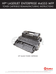
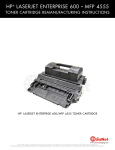
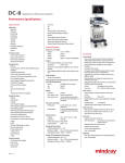
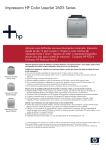
HP LASERJET 2600
®
CARTRIDGE REMANUFACTURING INSTRUCTIONS
HP ® LASERJET 2600 TONER CARTRIDGE
www.uninetimaging.com
© 2010 UniNet Imaging Inc. All trademark names and artwork are property of their respective owners. Product brand names mentioned are intended to show compatibility only.
UniNet Imaging does not warrant downloaded information. Unauthorized sale, reproduction or distribution of this article is prohibited. For additional support, please contact [email protected]
HP LASERJET 2600 • TONER CARTRIDGE REMANUFACTURING INSTRUCTIONS
REMANUFACTURING THE HP LASERJET 2600
BLACK & COLOR TONER CARTRIDGES
By the Technical Staff at UniNet
UPDATED MARCH 14, 2012
First released in May of 2005, the HP 2600 series of color laser printers are based on a 8 ppm, 600 DPI engine (2400 DPI with
RET). The 2600 cartridges consist of the toner supply, drum and waste chamber. Like the CLJ 4600, these machines use an
inline, or single-pass system. All four cartridges are stacked on top of one another and each color develops its own image which
is transferred to the paper by the transfer belt. This type of system is faster and allows for a higher quality print.
This is one of the first cartridges where HP/Canon really seems to have gone out of their way to make a toner cartridge very
difficult to remanufacture. The waste chamber (which consists of the waste chamber, OPC drum, PCR, wiper and recovery blades)
is plastic-welded/glued together. The drum axle/bushings are permanently attached to the waste chamber. The only way to get
into the waste chamber is to either physically break or cut the cartridge apart, or to cut the drum drive gear with a hack saw. New
drums are available with special gears, and new replacement waste chambers are now also available that include the waste
chamber, new removable drum axles/bushings, foam seals, electrical contacts, and PCR holders. The kit will also contain the
screws, springs, and plastic pins that will be needed to re-assemble the cartridge.
If you want to re-use the waste chamber, you will have to cut the OEM drum apart. This is explained in a later step. The waste
chamber for these cartridges is very small. The aftermarket toner has to be very efficient to prevent leakage due to the waste
over flowing.
The chips in these cartridges are the same as most other HP color cartridges, the chip does not need to be changed in order for
the cartridge to work. The toner low circuitry will be disabled, but after the user presses the “SELECT” button, the cartridge will
work. The display will then alternate from “READY” to “Unauthorized Supply in Use.”
PRINTERS BASED ON THE 2600 ENGINE
HP Color LaserJet 1600
HP Color LaserJet 2600n
HP Color LaserJet 2605dn
HP Color LaserJet 2605dtn
HP Color LaserJet CM1015 MFP
HP Color LaserJet CM1017 MFP
CARTRIDGES USED IN THESE MACHINES
Q6000A (Black)
2,500 pages at 5%
Q6001A (Cyan)
2,000 pages at 5%
Q6003A (Magenta)
2,000 pages at 5%
Q6002A (Yellow)
2,000 pages at 5%
*Pricing in U.S. American dollars.
$106.00 List*
$115.00 List*
$115.00 List*
$115.00 List*
As you can see from these prices (current as of April 2008), these are very profitable cartridges to remanufacture. With the
exception of the CLJ 1600, which ships with 1000 page starter cartridges, it is sometimes cheaper to buy a new machine than
to buy a full set of cartridges!
The Image Transfer Belt, or ETB as HP is calling it, is not a user replaceable part. It is designed so that a technician will need to
replace it. I looked in the service manual and on the HP web site but could not find a statement on the expected life of these
belts.
The basic workings of these cartridges is similar to the 4600/3500 series, but some advances have been made. Because of that,
we are including the cartridge theory here. If you are familiar with the 4600 or 3500 theory, you will notice that there are fewer
parts and the printing process is simpler.
www.uninetimaging.com
© 2012 UniNet Imaging Inc. All trademark names and artwork are property of their respective owners. Product brand names mentioned are intended to show compatibility only.
UniNet Imaging does not warrant downloaded information. Unauthorized sale, reproduction or distribution of this article is prohibited. For additional support, please contact [email protected]
HP LASERJET 2600 • TONER CARTRIDGE REMANUFACTURING INSTRUCTIONS
HP 2600 COLOR PRINTING THEORY
The color toner cartridge printing process happens in a series of stages or steps. For the purpose of this article, we will call them
stages. The above diagram shows the basic layout of the cartridges and how they relate to one another and the printer. In the
first stage, the Primary Charge Roller (PCR) places a uniform negative DC voltage on the OPC drum surface. The amount of the
negative DC voltage placed on the drum is controlled by the printer’s intensity setting.
In the second stage, the laser beam is fired onto a rotating mirror (called the scanner). As the mirror rotates, the beam is
reflected into a set of focusing lenses. The beam then strikes the drums surface, reducing the negative charge and leaving a
latent electrostatic image on the drum. The areas where the laser did not strike the drum will retain the higher negative charge.
Each color cartridge has its own laser and scanner units.
www.uninetimaging.com
© 2012 UniNet Imaging Inc. All trademark names and artwork are property of their respective owners. Product brand names mentioned are intended to show compatibility only.
UniNet Imaging does not warrant downloaded information. Unauthorized sale, reproduction or distribution of this article is prohibited. For additional support, please contact [email protected]
HP LASERJET 2600 • TONER CARTRIDGE REMANUFACTURING INSTRUCTIONS
The third or developing stage is where the toner is developed on the drum by the developing section (or supply chamber),
which contains the toner particles. The development stage is actually made up of two steps: toner charging, and the actual
development.
In the toner charging stage, the toner stirring blade turns inside the hopper. As it turns, friction causes a negative potential to
develop on the toner. In addition, a foam feed roller brings the toner to the developer roller and also places a negative charge on
the toner. These two charges ensure a uniform charge on the toner. Once the toner is properly charged, the toner will coat the
developer roller. The toner is also held onto the developer roller by another negative DC bias voltage. This voltage is controlled by
the printer’s intensity setting, and causes either more or less toner to be attracted by the developer roller. This in turn will either
increase or decrease the print density. The developer roller also has an AC bias signal placed on it which makes the jump from
the developer roller to the drum easier. The amount of toner on the developer roller is controlled by the doctor blade, which uses
pressure to keep the amount of toner on the roller constant. Attached to the doctor blade is what is called a developing sheet.
This sheet improves the print quality, and helps prevent toner scatter.
As the laser exposed areas of the OPC drum approach the developer roller, the toner particles are attracted to the drum’s surface
due to the opposite voltage potentials of the toner, and laser exposed areas of the OPC drum.
www.uninetimaging.com
© 2012 UniNet Imaging Inc. All trademark names and artwork are property of their respective owners. Product brand names mentioned are intended to show compatibility only.
UniNet Imaging does not warrant downloaded information. Unauthorized sale, reproduction or distribution of this article is prohibited. For additional support, please contact [email protected]
HP LASERJET 2600 • TONER CARTRIDGE REMANUFACTURING INSTRUCTIONS
The fourth stage is the transfer stage. This is where there are some large differences from monochrome printers. The first step
in the transfer stage is where the transfer roller (which is located directly opposite each OPC drum), places a positive DC bias
charge on the back of the ETB or transfer belt. Each toner cartridge has a separate transfer charge roller. At the same time, the
paper is moving between the OPC drum and the ETB. As the ETB passes the transfer charging roller, the positive charge is picked
up, and draws the negatively charged toner off the drum onto the paper. This process is repeated for each color cartridge. As the
toner piles onto the paper, the positive charge on the paper weakens as the paper runs through each cartridge. For this reason,
the charge is increased on the transfer charging roller for each successive color.
The paper separates from the ETB belt as the belt reaches the top of its path and turns back down to start the process again.
The static charge on the back of the paper is decreased with static charge eliminator. This helps stabilize the paper feed,
and also prevents toner flares (spots) under low temperature and low humidity conditions.
In the fifth stage, the image is then fused onto the paper by the fuser assembly. The fuser Assembly is comprised of the upper
heating assembly and lower pressure roller. The lower pressure roller presses the page up into the upper heating assembly which
then melts the toner into the paper. The upper heating assembly consists of a flexible sleeve with a ceramic heating coil inside.
This type of fuser affords “instant on” fusing with little to no wait time, and low power consumption.
www.uninetimaging.com
© 2012 UniNet Imaging Inc. All trademark names and artwork are property of their respective owners. Product brand names mentioned are intended to show compatibility only.
UniNet Imaging does not warrant downloaded information. Unauthorized sale, reproduction or distribution of this article is prohibited. For additional support, please contact [email protected]
HP LASERJET 2600 • TONER CARTRIDGE REMANUFACTURING INSTRUCTIONS
OPC DRUM CLEANING
The drum is cleaned after the image is transferred to the paper by the wiper blade. This part is fairly standard; the wiper blade
scrapes the toner off the drum, and the recovery blade guides it into the waste chamber. these cartridges do not use a transfer
plate to move the waste toner into the back of the cartridge.
PRINTER CALIBRATION
At the start of all this is the calibration cycle. The printer will calibrate itself whenever the printer is turned on, when a new toner
cartridge is installed, after 48 hours of run time, and at 150 page intervals. Calibration consists of a solid block and halftone of
each color being printed to the ETB. As the printed areas get to the top of the belt, a sensor will detect them, measure the
density, and adjust the printer accordingly. All of the calibration time settings are user controllable. There are also physical
calibrations of the gear train, and various rollers.
TONER LOW DETECTION
The last thing that needs to be discussed before getting to the actual remanufacturing, is the toner level detection. The 2600
printers determine cartridge life by a number of different ways. It counts the number of OPC drum rotations, and actual amount
of toner left. The amount of toner is also determined by an optical sensor that reads through a set of clear plastic lenses
mounted on the supply chamber. Each of these measurements is written to the chip.
Taking test prints, cartridge troubleshooting, as well as minor printer troubleshooting will be covered at the end of this article.
REQUIRED TOOLS
1. Conical boring tool, 2mm or .078” or 14-13 woodscrew
2. Drill, 2.5mm (for metal pin extraction)
3. Pliers (needle nose and gripping)
4. Hacksaw (for OPC drum cutting)
5. Hook tool (angled and straight)
6. Phillips screwdriver
7. Flathead screwdriver (small and standard size)
8. X-Acto Knife (for cutting plastic tabs)
9. Gapping tool (for doctor blade removal and assembly)
10. Plastic cement (for smartchip installation)
11. Small hammer (for plastic pin insertion)
12. Soldering tool or drill (optional, for alternate toner filling and cartridge seal assembly only)
REQUIRED SUPPLIES
1. Replacement toner for use in HP 2600 (Black: 2,500 pages; Cyan, Magenta, Yellow: 2,000 pages)
2. Replacement smartchip for use in HP 2600 (Black: 2,500 pages; Cyan, Magenta, Yellow: 2,000 pages)
9. Replacement OPC drum with special gears, for use in HP 2600/EP 307
10. Coating solution for the developer roller sleeve
11. Fill-plug seal adhesive, or sealing tape (required for filling and sealing toner)
OPTIONAL SUPPLIES
1. Replacement doctor blade
2. Replacement wiper blade
3. Quickseal™ adhesive (recommended for alternate cartridge seal assembly)
www.uninetimaging.com
© 2012 UniNet Imaging Inc. All trademark names and artwork are property of their respective owners. Product brand names mentioned are intended to show compatibility only.
UniNet Imaging does not warrant downloaded information. Unauthorized sale, reproduction or distribution of this article is prohibited. For additional support, please contact [email protected]
HP LASERJET 2600 • TONER CARTRIDGE REMANUFACTURING INSTRUCTIONS
CARTRIDGE DISASSEMBLY: METAL PIN REMOVAL
1. Locate the metal pin on the contact side of the cartridge. Drill a parallel hole (2.5mm x 3mm deep) just above it to allow
extraction with needle nose pliers. Carefully pull the metal pin out, maneuvering with the pliers. Do not force the pin out, as this
may damage the contact plates inside. The consequences are explained in Step 10.
PLASTIC PIN REMOVAL
2. Use a 2mm (.078”) conical boring tool (shown) or a 14-13 wood screw for this procedure.
Locate the upper white plastic pin hole on the non-contact side of the cartridge.
Thread three or four times to firmly anchor the tool into hole.
www.uninetimaging.com
© 2012 UniNet Imaging Inc. All trademark names and artwork are property of their respective owners. Product brand names mentioned are intended to show compatibility only.
UniNet Imaging does not warrant downloaded information. Unauthorized sale, reproduction or distribution of this article is prohibited. For additional support, please contact [email protected]
HP LASERJET 2600 • TONER CARTRIDGE REMANUFACTURING INSTRUCTIONS
3. Pull the pin straight out to dislodge it from the cartridge.
4. Pin extracted.
5. Using a scriber or small screwdriver, pry off the OPC drum shutter hinges from the top of the cartridge shown.
www.uninetimaging.com
© 2012 UniNet Imaging Inc. All trademark names and artwork are property of their respective owners. Product brand names mentioned are intended to show compatibility only.
UniNet Imaging does not warrant downloaded information. Unauthorized sale, reproduction or distribution of this article is prohibited. For additional support, please contact [email protected]
HP LASERJET 2600 • TONER CARTRIDGE REMANUFACTURING INSTRUCTIONS
6. Insert a flathead screwdriver between the two cartridge
sections shown to wedge them apart for separation.
7. Pull the sections apart far enough to grasp with your hands.
8. Carefully remove the tension springs from the tabs from both sides of the cartridge. The spring tabs are very fragile.
NOTE: Remember the positioning of both springs for reassembly. Their sizes are different!
The spring on the right that is marked with a black stripe is actually smaller and has more tension than the spring to the left.
www.uninetimaging.com
© 2012 UniNet Imaging Inc. All trademark names and artwork are property of their respective owners. Product brand names mentioned are intended to show compatibility only.
UniNet Imaging does not warrant downloaded information. Unauthorized sale, reproduction or distribution of this article is prohibited. For additional support, please contact [email protected]
HP LASERJET 2600 • TONER CARTRIDGE REMANUFACTURING INSTRUCTIONS
9. With the springs now removed, carefully separate the two
sections of the cartridge.
10. We can now see the internal electrical contact where the
metal pin was removed in Step 2. Any undue force in pulling
the pin can warp this metal contact, rendering it useless.
11. Unhook the drum shutter from the support tab on both sides of the drum unit.
www.uninetimaging.com
© 2012 UniNet Imaging Inc. All trademark names and artwork are property of their respective owners. Product brand names mentioned are intended to show compatibility only.
UniNet Imaging does not warrant downloaded information. Unauthorized sale, reproduction or distribution of this article is prohibited. For additional support, please contact [email protected]
HP LASERJET 2600 • TONER CARTRIDGE REMANUFACTURING INSTRUCTIONS
12. Drum shutter shown completely removed.
DRUM CARTRIDGE DISASSEMBLY: OPC REMOVAL
13. To remove the drum and access the internal components
beneath, we would need to cut off and remove the white
plastic non-contact spindle (circled) from the blue axle
housing/end cap shown. A hacksaw is required for this
procedure.
First, use a scriber or small flathead screwdriver to wedge a
gap between the OPC and the blue axle housing as shown. The
gap should be wide enough to saw through the white spindle
only, and avoid any unwanted damage to the end cap.
14. Carefully saw into the white plastic spindle and stop when
it reaches halfway. Do not saw all the way through.
15. Rotate the drum 90º in the direction shown and continue
cutting until the spindle reaches a breaking point. This will
keep the saw from dropping too far and damage any
components below. NOTE: Do not rotate the drum in the
opposite direction. Doing so can scratch up the wiper blade
below it.
www.uninetimaging.com
© 2012 UniNet Imaging Inc. All trademark names and artwork are property of their respective owners. Product brand names mentioned are intended to show compatibility only.
UniNet Imaging does not warrant downloaded information. Unauthorized sale, reproduction or distribution of this article is prohibited. For additional support, please contact [email protected]
HP LASERJET 2600 • TONER CARTRIDGE REMANUFACTURING INSTRUCTIONS
16. The OPC can now be removed.
17. Carefully lift the OPC and slide it out in the manner shown.
18. Push out the remaining spindle piece through the end cap.
19. Using a pair of needle nose pliers, gently lift up the PCR
from one side.
www.uninetimaging.com
© 2012 UniNet Imaging Inc. All trademark names and artwork are property of their respective owners. Product brand names mentioned are intended to show compatibility only.
UniNet Imaging does not warrant downloaded information. Unauthorized sale, reproduction or distribution of this article is prohibited. For additional support, please contact [email protected]
HP LASERJET 2600 • TONER CARTRIDGE REMANUFACTURING INSTRUCTIONS
20. Slide it out in the manner shown.
21. In case of contamination, clean with a small amount of
water and mild soap. Otherwise, use a simple dry pad.
22. First, remove the two Phillips screws from the wiper blade.
Be careful not to crease or damage the PCR contact strip on top.
www.uninetimaging.com
© 2012 UniNet Imaging Inc. All trademark names and artwork are property of their respective owners. Product brand names mentioned are intended to show compatibility only.
UniNet Imaging does not warrant downloaded information. Unauthorized sale, reproduction or distribution of this article is prohibited. For additional support, please contact [email protected]
HP LASERJET 2600 • TONER CARTRIDGE REMANUFACTURING INSTRUCTIONS
23. Use a scriber or flathead screwdriver to pry the wiper blade
assembly free from the adhesive strip behind it.
25. Clean the wiper blade with a dry, lint-free cotton pad.
24. Lift out the wiper blade from one side.
26. Use a vacuum to clean out the waste bin of used toner.
This will allow you to re-use the OEM adhesive strip to
reassemble the wiper blade. NOTE: Do not use compressed
air, as it will only scatter the used toner and coat the adhesive
strip, rendering it useless.
www.uninetimaging.com
© 2012 UniNet Imaging Inc. All trademark names and artwork are property of their respective owners. Product brand names mentioned are intended to show compatibility only.
UniNet Imaging does not warrant downloaded information. Unauthorized sale, reproduction or distribution of this article is prohibited. For additional support, please contact [email protected]
HP LASERJET 2600 • TONER CARTRIDGE REMANUFACTURING INSTRUCTIONS
DRUM UNIT REASSEMBLY
27. Install the cleaned wiper blade assembly. Make sure it
adheres well to the OEM adhesive strip underneath. Tighten
with the two Phillips screws, being careful not to crease or
damage the PCR contact strip on top.
28. Use a tester to check the electrical continuity and ensure
good contact between the wiper blade frame and the main
contact.
29. We now need to clean the PCR contact strip and black PCR
saddles where residual toner may still be present.
30. Using a cotton tip swab, clean the edges and underlining
of the PCR blade.
www.uninetimaging.com
© 2012 UniNet Imaging Inc. All trademark names and artwork are property of their respective owners. Product brand names mentioned are intended to show compatibility only.
UniNet Imaging does not warrant downloaded information. Unauthorized sale, reproduction or distribution of this article is prohibited. For additional support, please contact [email protected]
HP LASERJET 2600 • TONER CARTRIDGE REMANUFACTURING INSTRUCTIONS
31. Clean the black PCR saddles on both sides of the
cartridge, using a cotton tip swab. Apply a small amount of
isopropyl alcohol for best results.
32. Apply a small amount of conductive grease into the
saddles. Do not over-lubricate them.
33. Slide the cleaned PCR into the saddle on one side, then place the other side using a pair of needle nose pliers.
www.uninetimaging.com
© 2012 UniNet Imaging Inc. All trademark names and artwork are property of their respective owners. Product brand names mentioned are intended to show compatibility only.
UniNet Imaging does not warrant downloaded information. Unauthorized sale, reproduction or distribution of this article is prohibited. For additional support, please contact [email protected]
HP LASERJET 2600 • TONER CARTRIDGE REMANUFACTURING INSTRUCTIONS
NON-CONTACT
SPINDLE INSERT
& SMALL SCREW
PRE-INSERTED
DRIVE/CONTACT
SPINDLE
34. A new replacement drum for use in HP 2600/EP 307 can now be installed.
The new drum must also include a pre-inserted drive/contact spindle, a separate non-contact spindle, and small screw.
B
A
35. First, lubricate the interior of the blue axle housing on both
sides of the cartridge with a minimum amount of white
bearing grease.
Insert the new non-contact spindle into the non-contact axle
housing shown.
36. Carefully slide the new replacement drum drive/contact
side into the contact axle housing on the left (A).
Lower the drum non-contact side into place as shown on the
right (B).
Align the flange with the axle attachment.
www.uninetimaging.com
© 2012 UniNet Imaging Inc. All trademark names and artwork are property of their respective owners. Product brand names mentioned are intended to show compatibility only.
UniNet Imaging does not warrant downloaded information. Unauthorized sale, reproduction or distribution of this article is prohibited. For additional support, please contact [email protected]
HP LASERJET 2600 • TONER CARTRIDGE REMANUFACTURING INSTRUCTIONS
37. Insert the small screw on the outer end and tighten both pieces together with a Phillips screwdriver.
DEVELOPER UNIT DISASSEMBLY
38. Before disassembling, use a gapping tool to measure the gap between the doctor blade and the hopper.
This will ensure accurate reposition of the doctor blade during the final cartridge assembly process in Step 68.
www.uninetimaging.com
© 2012 UniNet Imaging Inc. All trademark names and artwork are property of their respective owners. Product brand names mentioned are intended to show compatibility only.
UniNet Imaging does not warrant downloaded information. Unauthorized sale, reproduction or distribution of this article is prohibited. For additional support, please contact [email protected]
HP LASERJET 2600 • TONER CARTRIDGE REMANUFACTURING INSTRUCTIONS
39. Remove the two screws from the contact (gearless) side
end plate.
40. Carefully remove the contact plate assembly without
distorting the contoured contact (circled). Use extreme caution
while separating it from the pillar.
41. The shape of the contoured contact must remain intact
when removed.
42. Remove the two screws from the non-contact (gear-side)
end-plate shown. Carefully remove this plate to access the
gears inside.
www.uninetimaging.com
© 2012 UniNet Imaging Inc. All trademark names and artwork are property of their respective owners. Product brand names mentioned are intended to show compatibility only.
UniNet Imaging does not warrant downloaded information. Unauthorized sale, reproduction or distribution of this article is prohibited. For additional support, please contact [email protected]
HP LASERJET 2600 • TONER CARTRIDGE REMANUFACTURING INSTRUCTIONS
Drive Coupling
Main Drive
Hopper Gear
Dev Roller Gear Feeding Roller Gear
43. Remove the three outer gears indicated by blue arrows.
These are the Drive Coupling, Main Drive and Feeding Roller
Gears. This will allow access to the roller support plate
beneath. Note the positioning of all the gears for reassembly.
44. With the outer gears removed, remove the screw that
holds the roller support plate in place.
45. Remove the screws from both ends of the doctor blade
assembly.
46. Using a small flathead screwdriver, pry the doctor blade
out from one side, then continue on the other side to release
it from the adhesive strip beneath it.
www.uninetimaging.com
© 2012 UniNet Imaging Inc. All trademark names and artwork are property of their respective owners. Product brand names mentioned are intended to show compatibility only.
UniNet Imaging does not warrant downloaded information. Unauthorized sale, reproduction or distribution of this article is prohibited. For additional support, please contact [email protected]
HP LASERJET 2600 • TONER CARTRIDGE REMANUFACTURING INSTRUCTIONS
47. Carefully lift the doctor blade out as shown.
48. Gently clean the working edge of the doctor blade with a
soft pad. CAUTION: The working edge is made of coated steel
that can be easily damaged by solvents or applying excessive
pressure.
49. You can now remove the developer roller sleeve. Note that
the feeding roller cannot be taken out.
50. Secure the two bushings and clean the developer roller
sleeve with compressed air. Alternate with a lint-free cotton
pad. Be sure to clean the two bushings thoroughly.
DEVELOPER ROLLER SLEEVE COATING SOLUTION RECOMMENDED
This universal coating solution extends the life of the sleeve by applying a coating of Teflon and sealants to the transfer layer. The
coating fills in surface scratches and provides much needed lubrication to the sleeve to prevent wear that can lead to failure.
1. Pre-clean the developer roller sleeve with a dry lint-free cloth to remove residual toner and surface contaminants.
2. SHAKE WELL and pour a few drops of the solution onto a cotton pad. It MUST be a lint-free.
3. Apply the solution in a back and forth circular motion along the axis of the sleeve. Go around at least twice for a thin even coat.
4. Allow to dry for 3 to 5 minutes before installing into the cleaned cartridge.
www.uninetimaging.com
© 2012 UniNet Imaging Inc. All trademark names and artwork are property of their respective owners. Product brand names mentioned are intended to show compatibility only.
UniNet Imaging does not warrant downloaded information. Unauthorized sale, reproduction or distribution of this article is prohibited. For additional support, please contact [email protected]
HP LASERJET 2600 • TONER CARTRIDGE REMANUFACTURING INSTRUCTIONS
51. Use a vacuum to clean residual toner from the roller and
hopper. Secure the foam seal at each end for reassembly.
You must now follow one of the following options:
REFILLING THE TONER HOPPER
52. Refilling can be done through the opening between the
mag roller and the feeding roller. Use a 12mm beak and load
the proper toner amount.
To refill the toner hopper now, follow Steps 53 and 54, then
skip to step 68.
To install a cartridge seal, skip to Step 55.
53. Insert the bushings on each end of the developer roller
and slide it into place, gear-side first as shown.
Proceed directly to the final cartridge assembly Instructions
on Step 68.
www.uninetimaging.com
© 2012 UniNet Imaging Inc. All trademark names and artwork are property of their respective owners. Product brand names mentioned are intended to show compatibility only.
UniNet Imaging does not warrant downloaded information. Unauthorized sale, reproduction or distribution of this article is prohibited. For additional support, please contact [email protected]
HP LASERJET 2600 • TONER CARTRIDGE REMANUFACTURING INSTRUCTIONS
ALTERNATE QUICKSEAL™ ASSEMBLY
54. A Quickseal™ adhesive is recommended for this procedure.
It offers a fast and easy way to seal the hopper without splitting the cartridge. No clips, rails or insertion tools are needed.
55. With the exit seal removed, be sure to clean the hopper
thoroughly before installing the new seal.
Using a small flathead screwdriver, force the used exit seal
plug out as shown.
56. Bend both ends of the seal backward exactly as shown.
57. Insert the folded tips through the exit seal port opening as
shown. Avoid peeling the adhesive backing during insertion.
www.uninetimaging.com
© 2012 UniNet Imaging Inc. All trademark names and artwork are property of their respective owners. Product brand names mentioned are intended to show compatibility only.
UniNet Imaging does not warrant downloaded information. Unauthorized sale, reproduction or distribution of this article is prohibited. For additional support, please contact [email protected]
HP LASERJET 2600 • TONER CARTRIDGE REMANUFACTURING INSTRUCTIONS
58. With the seal completely inserted, pull the white adhesive
backing to reveal a small section.
59. Adhere the small section to the hopper to secure the seal
as shown.
60. With the seal in place, pull the white backing to reveal the
remaining portion.
61. Apply pressure to properly adhere the remaining seal to
the hopper.
www.uninetimaging.com
© 2012 UniNet Imaging Inc. All trademark names and artwork are property of their respective owners. Product brand names mentioned are intended to show compatibility only.
UniNet Imaging does not warrant downloaded information. Unauthorized sale, reproduction or distribution of this article is prohibited. For additional support, please contact [email protected]
HP LASERJET 2600 • TONER CARTRIDGE REMANUFACTURING INSTRUCTIONS
62. Install the exit seal port plug to complete assembly.
REFILLING THE TONER HOPPER
63. Using a soldering tool, burn a small hole through the top of
the hopper. This will serve as an opening for refilling the
cartridge.
NOTE: Soldering is best for reducing the amount of internal
residue. If you prefer drilling, be sure to clean the cartridge
thoroughly before installing the seal.
64. Refill the cartridge and cover the opening with sealing tape
or fill plug seal adhesive.
65. Install the developer roller with the gear-side first.
www.uninetimaging.com
© 2012 UniNet Imaging Inc. All trademark names and artwork are property of their respective owners. Product brand names mentioned are intended to show compatibility only.
UniNet Imaging does not warrant downloaded information. Unauthorized sale, reproduction or distribution of this article is prohibited. For additional support, please contact [email protected]
HP LASERJET 2600 • TONER CARTRIDGE REMANUFACTURING INSTRUCTIONS
66. Install the contact plate and proceed to the next step for
final cartridge assembly instructions.
FINAL CARTRIDGE ASSEMBLY
67. Fit the doctor blade assembly into place as shown. Make
sure it adheres properly to the foam seal underneath.
68. Apply a very small amount of conductive grease to the
contact plate ends. Install the contact plate with the two
Phillips screws.
69. Prior to securing the doctor blade, insert a gapping tool
between the doctor blade and the hopper and adjust to the
original gap measurement taken in Step 39.
Install the two screws onto the doctor blade assembly.
www.uninetimaging.com
© 2012 UniNet Imaging Inc. All trademark names and artwork are property of their respective owners. Product brand names mentioned are intended to show compatibility only.
UniNet Imaging does not warrant downloaded information. Unauthorized sale, reproduction or distribution of this article is prohibited. For additional support, please contact [email protected]
HP LASERJET 2600 • TONER CARTRIDGE REMANUFACTURING INSTRUCTIONS
JOINING THE CARTRIDGE SECTIONS
70. Join both sections aligning the pin insertion points.
Insert the metal pin back into place as shown until a click is heard.
71. Insert the plastic pin halfway with your finger as shown.
72. Using a small hammer, tap in the remaining portion of the
plastic pin until it is completely inserted.
www.uninetimaging.com
© 2012 UniNet Imaging Inc. All trademark names and artwork are property of their respective owners. Product brand names mentioned are intended to show compatibility only.
UniNet Imaging does not warrant downloaded information. Unauthorized sale, reproduction or distribution of this article is prohibited. For additional support, please contact [email protected]
HP LASERJET 2600 • TONER CARTRIDGE REMANUFACTURING INSTRUCTIONS
73. Install the appropriate tension springs to their original positions (refer to Step 8).
74. Cartridge assembly complete.
REPLACING THE CHIP
75. Locate the OEM chip at the rear of the hopper. Using an
X-Acto knife, carefully cut away the melted top plastic tabs that
hold the chip in place.
www.uninetimaging.com
© 2012 UniNet Imaging Inc. All trademark names and artwork are property of their respective owners. Product brand names mentioned are intended to show compatibility only.
UniNet Imaging does not warrant downloaded information. Unauthorized sale, reproduction or distribution of this article is prohibited. For additional support, please contact [email protected]
HP LASERJET 2600 • TONER CARTRIDGE REMANUFACTURING INSTRUCTIONS
76. Place the X-Acto knife below the chip’s base and lift
upward to slide it out of its housing.
77. Apply a tiny amount of plastic cement along the inner
grooves of the chip housing prior to inserting the new chip.
This will bond the chip to the housing and keep it from falling
out during handling or transport.
NOTE: Do not apply excessive amounts of cement that can
spread onto and contaminate the contacts, rendering the chip
useless.
78. Slide the new aftermarket chip into the housing as shown.
Make sure the gold-plated contacts face outward. Allow the
cement to dry before testing the cartridge.
www.uninetimaging.com
© 2012 UniNet Imaging Inc. All trademark names and artwork are property of their respective owners. Product brand names mentioned are intended to show compatibility only.
UniNet Imaging does not warrant downloaded information. Unauthorized sale, reproduction or distribution of this article is prohibited. For additional support, please contact [email protected]
HP LASERJET 2600 • TONER CARTRIDGE REMANUFACTURING INSTRUCTIONS
TAKING TEST PRINTS
Demo Page:
1. Press the left and right Arrows simultaneously.
2. The Demo page will print out.
Configuration Page:
1. Press the left or right arrow until “REPORTS” appears on the display.
2. Press SELECT.
3. Press the left or right arrow until “CONFIG REPORT” appears on the display.
4. Press SELECT.
Supplies Status Page:
1. Press the left or right arrow until “REPORTS” appears on the display.
2. Press SELECT.
3. Press the left or right arrow until “SUPPLIES STATUS” appears on the display.
4. Press SELECT.
Cleaning Page:
1. Press the left or right arrow until “SERVICE” appears on the display.
2. Press SELECT.
3. Press the left or right arrow until “CLEANING MODE” appears on the display.
4. Press SELECT
5. A page will run slowly through the printer.
REPETITIVE DEFECT CHART
Developer Roller Sleeve
Primary Charge Roller
RS Roller
Transfer Rollers
ETB Rollers
Fuser Sleeve
Fuser Pressure Roller
OPC Drum
24.7mm
26.7mm
32.9mm
37.7mm
54.5mm
56.6mm
62.8mm
75.4mm
CARTRIDGE TROUBLESHOOTING
Dirty Primary Charge Roller (PCR):
Will show on the test print as vertical gray streaks down the page or as a gray
background throughout the page. If there is any physical damage, it will repeat
at intervals of 26.7mm.
Dirty PCR Connection:
Will result in dark black horizontal bars across the page or as shading throughout
the page.
Scratched Drum:
Will show up as a very thin, perfectly straight line that runs from the top to the
bottom of the test page.
Chipped Drum:
Will result in a dot or series of dots that repeat at 75.4mm intervals.
Damaged Developer Roller Sleeve:
Will either leave a mark or a blank spot (depending on the type of damage) at
intervals of 24.7mm.
Light Damaged Drum:
Will show up as a shaded area on the test print that should be white.
Again this will repeat at intervals of 75.4mm.
Bad Wiper Blade:
Will result in vertical gray lines down the page or as shading across the entire page.
In either case there will be a film of toner on the drum surface.
www.uninetimaging.com
© 2012 UniNet Imaging Inc. All trademark names and artwork are property of their respective owners. Product brand names mentioned are intended to show compatibility only.
UniNet Imaging does not warrant downloaded information. Unauthorized sale, reproduction or distribution of this article is prohibited. For additional support, please contact [email protected]
HP LASERJET 2600 • TONER CARTRIDGE REMANUFACTURING INSTRUCTIONS
COMMON PRINTER ERROR MESSAGES
10.000x
Supply Error/Chip cannot be read or cartridge not properly installed:
10.0000
Black cartridge
10.0001
Cyan cartridge
10.0002
Magenta cartridge
10.0003
Yellow cartridge
10.100x
10.1000
10.1001
10.1002
10.1003
Supply Error/Missing Cartridge:
Black cartridge
Cyan cartridge
Magenta cartridge
Yellow cartridge
50.X
50.1
50.2
50.3
Fuser Error:
Low Fuser Temp
Slow Fuser
High Fuser Temp
51.2X
51.20
51.21
51.22
51.23
Printer Error:
Black Scanner error
Cyan Scanner error
Magenta Scanner error
Yellow Scanner error
CALIBRATE NOW
If you are experiencing problems with color in the printouts, the “CALIBRATE NOW” feature can be run.
This forces a calibration cycle to run. This procedure does not always fix the issue, but it can.
1. Press the left or right arrow until “SYSTEM SETUP” appears on the display.
2. Press SELECT.
3. Press the left or right arrow until “PRINT QUALITY” appears on the display.
4. “CALIBRATE COLOR” will appear on the display.
5. Press SELECT.
6. Press the left or right arrow until “CALIBRATE NOW” appears on the display.
7. Press SELECT
8. Press the “SELECT” to start the calibration.
www.uninetimaging.com
© 2012 UniNet Imaging Inc. All trademark names and artwork are property of their respective owners. Product brand names mentioned are intended to show compatibility only.
UniNet Imaging does not warrant downloaded information. Unauthorized sale, reproduction or distribution of this article is prohibited. For additional support, please contact [email protected]