1
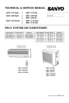
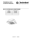
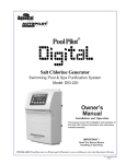
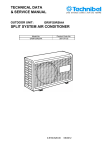
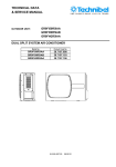
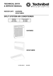
TECHNICAL DATA
& SERVICE MANUAL
INDOOR UNIT:
CAF184MR5IA-
SPLIT SYSTEM AIR CONDITIONER
Model No.
CAF184MR5IA-
Product Code No.
387106971
0.8180.393.1
09/2006
• Ground the unit following local electrical codes.
• The Yellow/Green wire cannot be used for any connection
different from the ground connection.
• Connect all wiring tightly. Loose wiring may cause overheating
at connection points and a possible fire hazard.
• Do not allow wiring to touch the refrigerant tubing, compressor,
or any moving parts of the fan.
• Do not use multi-core cable when wiring the power supply and
control lines. Use separate cables for each type of line.
IMPORTANT!
Please read before installation
This air conditioning system meets strict safety and operating
standards.
For the installer or service person, it is important to install or
service the system so that it operates safely and efficiently.
For safe installation and trouble-free operation, you must:
• Carefully read this instruction booklet before beginning.
• Follow each installation or repair step exactly as shown.
• Observe all local, state and national electrical codes.
• Pay close attention to all warning and caution notices given in
this manual.
•The unit must be supplied with a dedicated electrical line.
When transporting
Be careful when picking up and moving the indoor and outdoor
units. Get a partner to help, and bend your knees when lifting to
reduce strain on your back. Sharp edges or thin aluminium fins on
the air conditioner can cut your fingers.
WARNING
When installing...
... In a ceiling or wall
Make sure the ceiling/wall is strong enough to hold the unit-weight.
It may be necessary to build a strong wooden or metal frame to
provide added support.
This symbol refers to a hazard or unsafe practice which can result
in severe personal injury or death.
... In a room
Properly insulate any tubing run inside a room to prevent
"sweating", which can cause dripping and water damage to walls
and floors.
CAUTION
This symbol refers to a hazard or unsafe practice which can result
in personal injury or product or property damage.
... In moist or uneven locations
Use a raised concrete base to provide a solid level foundation for
the outdoor unit.
This prevents damage and abnormal vibrations.
If necessary, get help
These instructions are all you need for most installation sites and
maintenance conditions.
If you require help for a special problem, contact our sale/service
outlet or your certified dealer for additional instructions.
... In area with strong winds
Securely anchor the outdoor unit down with bolts and a metal
frame. Provide a suitable air baffle.
In case of improper installation
The manufacturer shall in no way be responsible for improper
installation or maintenance service, including failure to follow the
instructions in this document.
... In a snowy area (for heat pump-type systems)
Install the outdoor unit on a raised platform that is higher than
drifting snow. Provide snow vents.
SPECIAL PRECAUTIONS
When connecting refrigerant tubing
• Keep all tubing runs as short as possible.
• Use the flare method for connecting tubing.
• Apply refrigerant lubricant to the matching surfaces of the flare
and union tubes before connecting them; screw by hand and
then tighten the nut with a torque wrench for a leak-free
connection.
• Check carefully for leaks before starting the test run.
• During installation, connect before the refrigerant system and
then the wiring one; proceed in the reverse orden when removing
the units.
WARNING
When wiring
ELECTRICAL SHOCK CAN CAUSE SEVERE
PERSONAL INJURY OR DEATH. ONLY A QUALIFIED,
EXPERIENCED ELECTRICIANS SHOULD ATTEMPT
TO WIRE THIS SYSTEM.
NOTE:
Depending on the system type, liquid and gas lines may be either
narrow or wide. Therefore, to avoid confusion, the refrigerant
tubing for your particular model is specified as narrow tube for
liquid, wide tube for gas.
• Do not supply power to the unit until all wiring and tubing are
completed or reconnected and checked, to ensure the grounding.
• Highly dangerous electrical voltages are used in this system.
Carefully refer to the wiring diagram and these instructions when
wiring.
Improper connections and inadequate grounding can cause
accidental injury and death.
When servicing
• Turn the power OFF at the main power board before opening
the unit to check or repair electrical parts and wiring.
• Keep your fingers and clothing away from any moving parts.
• Clean up the site after the work, remembering to check that no
metal scraps or bits of wiring have been left inside the unit being
serviced.
• Ventilate the room during the installation or testng the refrigeration
system; make sure that, after the installation, no gas leaks are
present, because this could produce toxic gas and dangerous
if in contact with flames or heat-sources.
2
Table of Contents
Page
4
4
5
6
1. SPECIFICATIONS
1-1 Unit specifications
1-2 Major Component specifications
1-3 Other Component specifications
2. DIMENSIONAL DATA
7
3. ELECTRICAL DATA
8
8
3-1 Electric Wiring Diagrams
9
9
11
12
4. FUNCTION
4-1 Operation Functions
4-2 Protective Functions
4-3 Drain Pump and Float Switch
5. TROUBLESHOOTING
13
6. CHECKING ELECTRICAL COMPONENTS
17
17
18
18
6-1 Measurement of Insulation Resistance
6-2 Checking Continuity of Fuse on PCB Ass'y
6-3 Checking Motor Capacitor
3
1. SPECIFICATIONS
1-1 Unit Specifications
CAF184MR5IAPower source
220 - 240 V ~ 50 Hz
Voltage rating
230 V
Performance
Capacity
Air circulation
High/Med./Low
m³/h
Features
Controls/Temperature controls
Control unit
Timer
Fan speed
Airflow direction
Air Filter
Power noise level
Refrigerant tubing connections
Refrigerant
tube diameter
Refrigerant
Refrigerant tube kit / Air clean filter
Dimensions & Weight
Dimensions
Unit
Ceiling panel
Package dimensions
Unit
Ceiling panel
Weight
Unit
Ceiling panel
See catalogue with the requested matching
790/660/580
Microprocessor/ I.C. thermostat
Wireless remote control unit
ON/OFF 24 hours & Daily program, 1-hour OFF
3 and Auto /1(Hi)
Auto
Vertical
High/Med./Low
dB-A
Narrow tube
Wide tube
mm(in.)
mm(in.)
Height
Width
Depth
Height
Width
Depth
Height
Width
Depth
Volume
Height
Width
Depth
Volume
Net
Shipping
Net
Shipping
mm
mm
mm
mm
mm
mm
mm
mm
mm
m3
mm
mm
mm
m3
kg
kg
kg
kg
4
Washable, Anti-Mold
54/49/46
Flare type
6,35 (1/4)
9,52 (3/8)
R410A
Optional / --------------
273
575
575
64
730
730
380
744
650
0,18
110
800
800
0,07
18,2
22,7
2,50
4,70
1-2 Major Component Specifications
CAF184MR5IAController PCB
Part No.
Controls
Control circuit fuse
CB-XMRV183EH
Microprocessor
250 V - 3,15 A
Remote Control Unit
RCS-3MVHPS4E
Fan & Fan Motor
Type
Q'ty ……. Dia. and lenght
Fan motor model…Q'ty
No. of poles…rpm (230 V, High / 2nd / 3rd / Low)
Running Amps
Power input
Coil resistance (Ambient temp. 20 °C )
Safety devices
mm
A
W
Ω
Type
Operating temp. Open
Close
°C
Run capacitor
µF
VAC
Flap Motor
Type
Model
Rating
Coil resistance (Ambient temp. 25 °C )
Ω
Heat Exch. Coil
Coil
Rows
Fin pitch
face area
Centrifugal fan
1…. Ø 280 / L 166
K35407 M01972 …1
4… 880 / 740 / 660 / 290
0,27
61
BLU-BRN: 33,9÷39,1
BLU-BLK: 325÷374
BLK-GRY: 78,7÷90,5
GRY-RED: 49,7÷57,2
RED-WHT/YEL: 155÷178
Internal thermal protector
150 ± 10
Automatic
2
400
Stepping motor
MP24GA2
DC 12 V
400±7%
Aluminium plate fin / Copper tube
1
1,3
mm
0,258
m2
DATA SUBJECT TO CHANGE WITHOUT NOTICE
5
1-3 Other Component Specifications
Trasformer (TR)
Rating
CAF184MR5IA-
ATR-I55
AC 230 V, 50/60 Hz
13.7 V - 0.4 A
5.48 VA
Primary (WHT-WHT): 307 ± 10%
Secondary (BRN-BRN): 1.8 ± 10%
150°C
Primary
Secondary
Capacity
Ω (at 25°C)
Coil resistance
Thermal cut-off temp.
Thermistor ( Coil sensor TH1)
Resistance
κΩ
DTN-C583G3U-TKS121B
0 °C: 188,0 ± 4%
Thermistor ( Room sensor TH2)
Resistance
κΩ
DTN-C502H3T-TKS128B
25 °C: 5,0 ± 3%
Drain pump
Model
Rating
PC 309564003
220-240 V - 50 Hz
14 W
0,4 l/min
Voltage
Input
Total head capacity
Safety float switch
Model
Contact rating
BI 1300 2725
230 V AC/DC - 0,5 A
• Indoor heat exchanger sensor
• Indoor air temp sensor
10
200
9
180
160
Resistance (Ω)
Resistance (Ω)
8
7
6
5
4
3
140
120
100
80
60
2
40
1
20
10
15
20
25 30
35
Temperature (°C)
0
40
6
0
10 20 30 40 50 60 70 80 90
Temperature (°C)
2. DIMENSIONAL DATA
Unit: mm
7
3. ELECTRICAL DATA
3-1 Electric Wiring Diagrams
8
4. FUNCTIONS
4-1. Operation Functions
■ Functions of the main unit controller
■ SENSOR DRY
1 OFF
: • Used to stop the unit when the remote
(Self-diagnostics) controller is unavailable.
• Used when service inspection is performed.
2 ON
: • During normal operation: Starts operation
from the remote controller.
• Emergency operation: When the remote
controller is unavailable, moving this switch
from the OFF position to the ON position
starts automatic operation.
3 TEST
: • Used when operating performance are
checked.
• Used when pump-down is carried out.
(Operates at the rated frequency. At this
time, the main unit lamp flashes, and the
remote controller signal cannot be
received.)
4 DEMO
: • This function is for shop displays. Ordinarily
it is not used.
• Used during servicing.
During automatic operation, the system adjusts the room
temperature and fan speed according to the conditions in the
room, in order to maintain a comfortable room environment.
SENSOR DRY operation
• DRY operation is as shown in the figure below.
Load
COOL zone
A zone
B zone
Conditions are monitored at all
times when the room temperature
is below 15°C.
DRY A
The compressor operation frequency varies depending on the
relative humidity.
The indoor fan operates with 1/f fluctuation.
■ Automatic operation
● Operating mode selection
When automatic operation is selected, the indoor and outdoor
temperature sensors function, and either HEAT, DRY, or COOL
mode operation is selected automatically.
Set
temperature
(standard)
Indoor temperature
Outdoor air temperature
(Approx.) 15°C
22°C
27°C
(Approx.)
COOL
mode
22°C
DRY
mode
20°C
18°C
HEAT
mode
DRY B
The compressor operates at a low operating frequency.
The indoor fan operates with 1/f fluctuation.
Monitor
• Monitoring operation takes place when the room temperature
is below 15°C.
• When the monitoring range is entered, the compressor stops,
and the indoor fan operates at LL.
27°C
Temperature
at which
operation
starts
(Range:
20 – 26°C)
■ PAM-α control
• In order to further improve inverter performance, control is
switched between PWM control at low operation speeds, and
PAM control at high operation speeds, making the most
effective use of power.
24°C
• When multiple indoor units are connected and this unit is
started while another indoor unit is operating, the operating
mode is as shown in the table below.
Multi
operating mode
Operating mode
after change
COOL
DRY
DRY
DRY
COOL
HEAT
HEAT
DRY
HEAT
HEAT
Operating mode
before change
HEAT
• If the remote controller is used to start automatic operation, a
differing-mode check is performed if the operating modes are
not the same.
● Desired-temperature memory
• The set temperature in the program can be changed as
desired within the range of ±4°C. This temperature can then
be stored. During automatic operation, press the temperature
setting buttons to change the temperature.
9
■ HIGH POWER
■ Lamp colors
Raises the power but remains in the same operating mode.
This function is set with the HIGH POWER button on the remote
controller.
(It is set regardless of the temperature and fan speed settings.)
Operation lamp
HEAT operation : Red
DRY operation : Orange
● HIGH POWER operation from the remote controller
The unit operates at maximum output for 15 minutes,
regardless of the desired temperature.
The fan speed is 1 step above “High.”
COOL operation : Green
TIMER lamp
: Green
■ ON timer operation
Frequency
MAX
• Operation starts when the time set for the ON timer is reached.
When a time is set, the TIMER lamp illuminates.
• The below comfort timer programming is performed.
A comfort time is calculated from the set temperature and the
room temperature, either 60 minutes prior or 30 minutes prior to
the set ON timer time, and operation is started in advance of
the set ON time. (The indoor fan speed is “Medium.”)
[COOL]
Indoor temperature – Set temperature = Temperature difference
[HEAT]
Set temperature – Indoor temperature = Temperature difference
Time
0
15 min.
Start
5 min.
End
NOTE
• When HIGH POWER operation ends, the unit operates at low
Hz for 5 minutes, regardless of the thermostat OFF conditions.
• When in DRY mode, operation is in the cooling zone.
• When in HEAT mode, defrosting does not occur during HIGH
POWER operation.
• If HIGH POWER is set while defrosting is in progress, HIGH
POWER operation begins after defrosting ends.
• HIGH POWER operation cannot be set from the remote
controller when the unit is stopped.
• HIGH POWER operation and ECONOMY operation cannot be
used at the same time. The function set last takes priority.
Temperature difference (°C)
Advance start time (min.)
12 < Temperature difference
60
6 < Temperature difference
30
NOTE
This function does not operate if the ON timer standby time is
less than 30 minutes.
■ OFF timer operation
• Operation stops when the time set for the OFF timer is
reached.
When a time is set, the TIMER lamp illuminates.
■ ECONOMY
• When ECONOMY operation is set, the temperature and fan
speed settings will be adjusted automatically to allow
comfortable sleep.
• When ECONOMY operation is set, “ mark” appears on the
remote controller.
■ Timer backup
• If the indoor unit is unable to receive the timer time-end signal
when the ON or OFF time is reached, then timer time-end
occurs according to the indoor unit backup timer within
approximately 26 minutes.
• Operation stops if there are no operator controls for 25 hours or
longer after unit operation switched from OFF to ON by use of
ON timer operation.
● COOL and DRY modes
• The indoor unit fan speed is automatically lowered for quiet
operation.
• The temperature setting is raised by 1°C one hour after
ECONOMY operation is set.
● HEAT mode
• The indoor unit and outdoor unit fan speeds are
automatically lowered for quiet operation.
• The temperature setting is lowered by 3°C one hour after
ECONOMY operation is set.
In addition, the temperature setting is lowered by 4°C after
two hours have passed.
10
4-2. Protective Functions
■ Cold-air prevention during heating
During HEAT operation, the temperature of the indoor heat
exchanger is used to control the frequency and lessen the load
on the compressor before the protective device is activated.
During heating, the fan speed is set to “LL” (very low) or stopped.
As the temperature of the indoor heat exchanger rises, the fan
speed is changed to the set speed.
Indoor heat exchanger
temperature (°C)
■ Overload prevention during heating
Indoor heat exchanger
A. Control start
B. Control end
A
Approx.
53
Approx.
47
Normal operation
B
a
b
c
At start of operation
d
a area: Automatic capacity control
b When Point A has been exceeded, the operation frequency is
LL
reduced by a certain proportion.
Stopped
c area: Frequency increase is prohibited.
d At Point B and below, overload prevention is ended and
Indoor heat exchanger
temperature (°C)
During COOL or DRY operation, freezing is detected and
operation is stopped when the temperature of the indoor heat
exchanger matches the conditions below.
1 Freeze-prevention operation is engaged when the
temperature of the indoor heat exchanger is below 6°C.
2 Restart after freeze-prevention operation occurs when the
temperature of the indoor heat exchanger reaches 8°C or
above.
• This prevents remote controller signal interference when two
air conditioners are installed next to each other.
Ordinarily, the address is set to A. If it is necessary to change
the address, follow the procedure below. If 3 or more (up to 4)
units are installed, use remote controllers that are intended for
servicing use.
1 Switch the address setting to “B” by removing the tab
marked “A” on the remote controller.
2 Insert dry-cell batteries into the remote controller and press
the ACL button. Then attach the cover.
3 Open the air intake grille on the indoor unit, and move the
operation switch to the DEMO position.
4 Press the ON/OFF operation button on the remote
controller. Check that the “beep” signal-received sound is
heard from the indoor unit.
5 Move the operation switch to the ON position, and close the
intake grille.
6 Operate the remote controller. Check that the “beep” signalreceived sound is heard from the indoor unit.
B
2
*
a
b
c
d
a area: Automatic capacity control
b When the temperature drops below Point A, the operation
frequency is reduced by a certain proportion.
c area: Frequency increase is prohibited.
d When the temperature reaches Point C or above, freezing
prevention is ended and control is the same as in the a area.
*
Approx. 40
■ Changing the remote controller address
C
A
30
NOTE
• The fan speed is forcibly changed to “LL” beginning 30 seconds
after the thermostat turns OFF.
• Normal operation refers to operation when the room
temperature has approached the set temperature.
• When HEAT operation starts, the indoor fan is stopped until the
temperature of the indoor heat exchanger reaches 20°C or
higher, or until the room temperature reaches 15°C or higher.
■ Freeze prevention
8
25
Indoor heat exchanger
temperature (°C)
control is the same as in the (a) area.
6
Set fan speed
High
When the temperature drops to below 2°C (continuously for 2
minutes or longer), the compressor stops.
Once the freeze condition is detected, the air conditioner will
work less than the maximum frequency until it is turned off.
11
4-3. Drain Pump and Float Switch
5. TROUBLESHOOTING
■ Precautions before performing inspection or repair
● After checking the self-diagnostics monitor, turn the power OFF before starting inspection or repair.
● High-capacity electrolytic capacitors are used inside the outdoor unit controller (inverter). They retain an electrical charge
(charging voltage DC 280 V) even after the power is turned OFF, and some time is required for the charge to dissipate. Be
careful not to touch any electrified parts before the controller LED (red) turns OFF.
If the outdoor controller is normal, approximately 30 seconds will be required for the charge to dissipate. However, allow at
least 5 minutes for the charge to dissipate if there is thought to be any trouble with the outdoor controller.
After inspection or repair is completed, be sure to move the operation switch to the DEMO position, turn the power ON, and
erase the diagnostics contents.
■ Method of self-diagnostics
If the indoor unit operation lamp is flashing every 0.5 seconds, follow the
procedure below to perform detailed trouble diagnostics.
NOTE
1: If the operation lamp flashes every 0.5 seconds immediately when the power is turned ON,
there is an external ROM (OTP data) failure on the indoor circuit board or a board insertion
problem, or the board has not been installed.
2: The failure mode is stored in memory even when the power is not ON. Follow the procedure
below to perform diagnostics.
PROCEDURE
1 Turn the power switch ON.
2 Move the operation selector on the remote control receiver to OFF (self-diagnostics).
3 If there is a sensor failure or a protective function has activated, self-diagnostics lamps 1, 2, and 3 will illuminate in the
following pattern: 5 seconds flashing (illuminated) + 2 seconds OFF. (Buzzer sounds once while lamps are OFF.)
Note: If there is no trouble, then self-diagnostics lamps 1, 2, and 3 do not illuminate, and the buzzer does not sound.
4 Diagnostics is completed when the buzzer sounds 3 beeps.
5 After inspection or repair is completed, be sure to move the operation switch on the indoor unit main body to the DEMO
position, turn the power ON, and erase the diagnostics contents. Then move the operation selector on the remote control
receiver to the OFF position and check that the diagnostics contents have been erased before using the unit.
<Indoor unit main body>
Operation switch
Ordinarily, be sure
this is always set to
NORMAL.
The DEMO position is
used for inspections
and similar
maintenance.
13
Operation selector
Ordinarily, be sure this is always set to ON.
The OFF and TEST positions are used for
inspections and similar maintenance.
Details of Self-Diagnostics
When the operation selector on the grille assy is moved from the ON or TEST position to the OFF (Self-diagnostics)
position, the indicator lamps will flash (or remain ON) for 5 seconds and then turn OFF for 2 seconds (buzzer sounds
once) to indicate the presence of a sensor failure or the activation of a protective function. Self-diagnostics is completed
when the buzzer sounds 3 beeps. If there is no trouble, the lamps do not flash. Also note that the corresponding parts
listed below may not be present in some models.
*
Other :
Timer lamp flashes (3-second intervals): I/D float switch activated.
NOTE :
If the operation lamp continues to flash (orange) even when the operation switch has been moved to
the OFF position, an indoor unit external ROM failure has occurred. (E14) After inspection or repair
is completed, be sure to move the operation switch (on the electrical box) to the DEMO position,
turn the power OFF and ON and erase the diagnostics contents.
Control 1
*
Initial selfdiagnostics
Only operation lamp
illuminates
Short-circuit terminals 2 and 4 on
the indoor unit terminal plate
No change
Change: Operation lamp and Service
lamp illuminate, and Timer lamp flashes
Change: Operation lamp and Service
lamp illuminate, and Timer lamp flashes
Control 2
Short-circuit terminals 2 and 3 on
the outdoor unit terminal plate
Change: Operation lamp and Service
lamp illuminate, and Timer lamp flashes
Change: only operation lamp illuminates
Probable location of malfunction
Indoor unit circuit board failure
Outdoor unit circuit board failure
Failure (open circuit, contact failure,
etc.) in the inter-unit cable
- Turn the power OFF before performing short circuiting work.
- During the self-diagnostics check, the check results are the first indication when the operation switch is moved to OFF
while the indicators are flashing after power ON →DEMO (5 seconds) →ON.
- Before performing the above checks, perform DEMO operation, and check that AC 220 V is output toterminals 1 and
2. If it is not output, there is a failure related to the indoor unit power.
14
■ If the self-diagnostics function fails to operate
• No indicators illuminate and the
indoor fan does not turn.
• Check the power voltage.
Check the indoor unit.
Blown
Is the fuse blown?
Normal
Replace the circuit
board or the fuse.
Replace the controller.
<Checking the indoor and outdoor units>
■ Checking the indoor unit
No.
Control
Check items (unit operation)
1
Set operation selector of indoor unit main
body to DEMO and start operation using the
remote controller.
• The rated voltage must be present between inter-unit cables 1 and 2.
• Connect a 5 kΩ resistor between inter-unit cables 2 and 3. When the
voltage at both ends is measured, approximately 12–15 V DC must
be output and the needle must fluctuate once every 8 seconds.
In addition, insert an LED jig and check that the LED flickers once
every 8 seconds.
● If there are no problems with the above, then check the outdoor unit.
■ Checking the outdoor unit
No.
Control
Check items (unit operation)
1
Apply the rated voltage between outdoor
unit terminals 1 and 2.
• The control panel LED (red) must illuminate.
2
Short-circuit the outdoor unit COM terminal
to the T-RUN terminal.
• The compressor and fan motor must turn ON.
● If there are no problems with the above, then check the indoor unit.
TEST/T-RUN terminals
● Using the TEST/T-RUN terminals
T-RUN
: Test run (compressor and fan motor turn ON.)
TEST/MV : Compresses time to 1/60th (accelerates
operation by 60 times faster than normal).
Fully opens the electric expansion valve.
15
<Noise malfunction and electromagnetic interference>
An inverter A/C operates using pulse signal control and high frequencies. Therefore, it is susceptible to the effects of external
noise, and is likely to cause electromagnetic interference with nearby wireless devices.
A noise filter is installed for ordinary use, preventing these problems. However, depending on the installation conditions, these
effects may still occur. Please pay attention to the points listed below.
■ Noise malfunction
This refers to the application of high-frequency noise to the signal wires, resulting in abnormal signal pulses and malfunction.
Locations most susceptible to noise
1. Locations near broadcast stations where
there are strong electromagnetic waves
2. Locations near amateur radio (short wave)
stations
3. Locations near electronic sewing machines
and arc-welding machines
Trouble
Either of the following trouble may occur.
1. The unit may stop suddenly during
operation.
2. Indicator lamps may flicker.
Correction
(The fundamental concept is to make the
system less susceptible to noise.)
— Insulate for noise or
distance from the noise source. —
1. Use shielded wires.
2. Move unit away from the noise source.
■ Electromagnetic interference
This refers to the noise generated by high-speed switching of the microcomputer and compressor. This noise radiates through
space and returns to electric wiring, affecting any wireless devices (televisions, radios, etc.) located nearby.
Locations most susceptible to noise
1. A television or radio is located near the
A/C and A/C wiring.
2. The antenna cable for a television or
radio is located close to the A/C and A/C
wiring.
3. Locations where television and radio
signals are weak.
Trouble
Correction
1. Noise appears in the television picture, 1. Select a separate power source.
or the picture is distorted.
2. Keep the A/C and A/C wiring at least 1 meter
2. Static occurs in the radio sound.
away from wireless devices and antenna cables.
3. Change the wireless device's antenna to a highsensitivity antenna.
4. Change the antenna cable to a BS coaxial cable.
5. Use a noise filter (for the wireless device).
6. Use a signal booster.
16
6. CHECKING ELECTRICAL COMPONENTS
6-1. Measurement of Insulation
Resistance
power plug
(Local supply)
● The insulation is in good condition if the resistance
exceeds 2MΩ.
Ground
probe
6-1-1. Power Supply Wires
Clamp the grounding terminal of the power plug with a
lead clip of the insulation resistance tester and
measure the resistance by placing a probe on both
the two power terminals. (Fig. 1)
Insulation
tester
NOTE
The shape of the power plug may differ from that
of the air conditioner which you are servicing.
Fig. 1
Then, also measure the resistance between the
grounding and other power terminals. (Fig. 1)
Terminal plate
6-1-2. Indoor Unit
Probe
Clamp a metallic part of the unit with the lead clip of
the insulation resistance tester and measure the
resistance by placing a probe on each terminal screw
where power supply lines are connected on the
terminal plate. (Fig. 2)
Clip
6-1-3. Outdoor Unit
Copper
tube or
metallic part
Insulation
tester
Fig. 2
Clamp an aluminum plate fin or copper tube with the
lead clip of the insulation resistance tester and
measure the resistance by placing a probe on each
terminal screw on the terminal plate. (Fig. 2)
Note that the ground line terminal should be skipped
for the check.
Probe
Clip
6-1-4. Measurement of Insulation
Resistance for Electrical Parts
Copper
tube or
metallic part
Disconnect the lead wires of the desired electric part
from terminal plate, capacitor, etc. Similarly disconnect
the connector. Then measure the insulation resistance.
(Figs. 3 and 4)
Insulation
tester
Fig. 3
From fan motor,
compressor and
other parts
NOTE
Refer to Electric Wiring Diagram.
If the probe cannot enter the poles because the hole is
too narrow then use a probe with a thinner pin.
Metallic
part
Probe
Clip
Insulation
tester
Fig. 4
17
7-2. Checking Continuity of Fuse
6-2.
on PCB Ass'y
Fuse
● Remove the PCB Ass’y from the electrical
component box. Then pull out the fuse from the PCB
Ass’y. (Fig. 5)
PCB Ass’y
● Check for continuity using a multimeter as shown in
Fig. 6.
Fig. 5
6-3.
7-3. Checking Motor Capacitor
Remove the lead wires from the capacitor terminals,
and then place a probe on the capacitor terminals as
shown in Fig. 7. Observe the deflection of the pointer,
setting the resistance measuring range of the
multimeter to the maximum value.
Fuse
Fig. 6
The capacitor is “good” if the pointer bounces to a
great extent and then gradually returns to its original
position.
The range of deflection and deflection time differ
according to the capacity of the capacitor.
Multimeter
Compressor motor
capacitor
Fan motor
capacitor
Fig. 7
18
R.D. 28 Reyrieux BP 131 - 01601 Trévoux CEDEX France
Tél. 04.74.00.92.92 - Fax 04.74.00.42.00