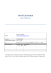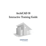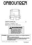
1
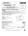
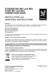
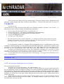
Lesson 01 - page 01
http://www.archiradar.com
original developer
translation:
Fabrizio Giammarco
Those lessons come directly from my internet pages. Referrals, images quality, impagination and
language, comes straight from there (with all related limits...). These are the rules: take it or leave it!
Foreword
So, here we are!
It seems that we’re ready to begin our first GDL-course LESSon (somethin’ less than a “real” lesson... ;)) )
But, before to start, we have to make our introductory statements:
1
2
3
4
5
You are using (at least) ArchiCAD 6.o or ArchiCAD 6.5*.
You are able to use it ... (you know his methodology and terminology).
You have familiarity in the management of the object libraries.
You are INTERESTED to learn.
You have your GDL manual.
*
this point (program version) is the less important... it’s enough to know that, when I make some specific
references (for example “click the icon down on the left”), I’m referring at those versions in particular.
If a thing isn’t there... well, you’ve to look for it elsewhere!!
It’s clear that this wouldn’t be a complete GDL programming course. It would help us to take some
confidence with the language, to understand the principles that regulate his “grammatical” operations and
will allow you to look at the user manual without the “fear” that characterizes first approaches of the
newbies on the programming stuff (and that often make them to close it comfortless).
If you have any particular requests or ideas, don’t understand something (or if you find every kind
of error), then please get in touch with us! A direct answer is much probable, but isn’t guaranteed;
corrections on the pages are sure, with the only limit of the time available.
For all of those that want a deeply knowledge of this language, i can suggest David Nicholson-Cole's
GDL Cooking Books.....
LESSON 01
Its real name must be lesson zero!! Is for all of you that don’t know REALLY nothin’ about GDL.
01.01 Let’s take some acquaintance with the interface.
We need to start far from here.....
Long time ago, in a far away galaxy... uh... little mistake!! ;))))
In order to use an object into an ArchiCAD file, we need to choose the correct icon from the tools
bar (it’s shaped by a chair); to change his settings (or to choose another one) double-click on the icon (or
press left arrow). The one that is opened is the object settings window: it would be a typical dialog window
with stacked cards, buttons and icons. Parameters, plan and section attributes, model attributes, list (compute)
attributes. It’s full up, but it’s the only window that you must use in order to “play” with an object into an
ArchiCAD project.
Really different is the life of an object creator! It must manage eleven (!!!) various windows. Feared?
Well, we don’t need necessarily to use all of them... for example, compute section is for a “deep” use of
the ArchiCAD, out from our sake.
20 egap - 10 nos eL
However, go on with me: from the File menu, choose the command: New library part / Object.
This shows up the main window that helps you to manage a GDL object; in the image below we can catch
a glimpse of his main parts:
her you can se by a simple
redn ot hp e t o gniward 2
preview of your object
let you to man ge objects
fragments, to dif er ntiate
his2dveworpat
her you can s b tw
dna stne opm c ,sret mar p
descriptors of your object
those ag-wind let you
man ge ( d tes ) 2d an 3d
tex scrip
tide yl ac hp rg n u o
tcejbo ru y fo strap d3 na d2
her you can d (an edit) al kind of par met s,
comp ne ts and escripto s f your bject
From the Script window tag-menus we can now edit:
Master Script:
2D Script:
3D Script:
Comments:
It's a text-style window, shared between 2d and 3d scripts. We don't need to
use it now, but soon we'll be back on it.
Here is the description of the "flat" geometry... another way to show a 2d symbol
into a plan view. Here GDL must be used! Of course, it's less easy, but much
more powerful than the "graphical" way. This window is used, usually, instead
of the previous; if both are used is this one that has the prevalence.
Is a description of solid geometry... here we need it to write many interesting
and mysterious things using the fascinating instructions of the GDL!!
Less frequently used, unfortunately!! Short text with comments or explanations
of the object here placed will be showed into the preview area.
Hint: turn on ballon help and move your mouse over this window... some brief notes will be showed.
01.02 A little bit of theory.
30 egap - 10 nos eL
Don’t forget that GDL is a complete programmer’s language. For a proper use we need to remember that:
• has an his own (firm) sintax;
• require a bit of discipline and much attention (more important when you take the first steps);
• when it works (and finally, it always works), give to the programmer great satisfaction.
On the ground of all there is Cartesian system: an origin and three orthogonal axis that define X,
Y, Z, directions into the space. Into this space we can define a solid using GDL instructions.
Easier of them is BLOCK command. Like most of you can imagine, it’s used to describe a parallelepiped,
a block, exactly. His syntax is:
BLOCK
p1, p2, p3
keyword
par met rs
GDL instructions starts with a keyword and needs parameters. Their specific meaning can be easily (hehehe)
learned, with a little help of gdl handbook or by the in-line help (if installed). In this particular instance the
three parameters describe length, width and height. Exactly in this order, they are used to show dimensions
along X, Y and Z axis.
Let’s start a deeper analysis: it’s clear that while the keyword (like all commands) must be used
exactly, a parameter (only used to describe values) allow more flexibility.
• GDL isn’t upper or lower case sensitive, but we strongly suggest to use upper for commands,
lower for all the rest;
• a space (at least) is required after a keyword;
• parameters must be separed by commas; spaces aren’t required, but maybe can help to read (and
to correct) the instructions;
• don't place commas between a keyword and the first parameter;
• after last parameter isn’t admitted any comma;
• his measure units are the same of your current archicad settings.
01.03 Some pratice.
Our first step into GDL world will be into a box..... a box of 2x1 meters and 80 centimeters high
Into new object’s window, choose GDL 3D text window. Write this instruction:
BLOCK
2, 1.5, 0.8
Despite your computer is set up to use commas as number separator, into GDL text a period is needed.
Let’s try to activate 3D view.
If all is going smooth, now you will see a prism!! It’s rough, but it’s just our own little creature. Take a look
at the bottom left of 3d window: there are two icons to activate / de-activate Cartesian axis. With axis view
turned on, we can now see three coloured arrows: they show X,Y and Z axis.
Our object must have a vertex exactly on the system origin: this is one of BLOCK characteristics.
Other commands give more freedom, but aren’t so easy to use.
Some of them could have many parameters. A slab is nothing else that a simple prism, with many vertexes,
and for each one we need to define an X and Y coordinate.
It’s now essential to understand how to write a multi-line command:to start new paragraphes is
allowed (without any command prejudice), provided that a comma must be placed at the end of every line,
with the exception of the last line.
Remember: for a better reading, after every parameter (an his comma) we strongly suggest a wise use of
carriage returns and spaces between parameters.
Please note that are called parameters either keyword parameters that object parameters.
40 egap - 10 nos eL
01.04 So... here we are: variables!!
Our Mr. BLOCK seems to be too much “square”....
Set his preview mode to hidden lines or shaded. Back now to main object window, try to modify
A and B values (x and y object’s dimensions).
Strange... nothing happens!!!
We’ve only (obviously) missed to update GDL text... the script don’t make any “call” for those variables.
Our prism is standalone (and a bit outlaw).... we’ll try to take it under our control!!
Into 3D gdl script window, replace 2 and 1.5 parameters with A and B letters:
BLOCK
A, B, 0.8
Let’s try to modify A and B values into main object window
Amazing... something happens!!! :))))
A and B are now two variable names, something that can assume any of a set of values. This will be useful
inasmuch as we can modify A and B values without editing 3d script: gdl interpreter built into ArchiCAD
automatically update it for us!
We want more now.... what about a variable height?? It’s easy... only another click on the “New” button!
A new line will come up, with a variable called “C”. Replace “C” letter with “Alt”... we’ve
just renamed a variable for a better readability. We can also change his name (properly his descriptive
name), his kind and his value.
“Type” is a pop-up menu that allow what kind of values can be recognized by our variable. Smarter users
surely noticed a division between “our” and preferred values (A and B for objects, much more for doors,
windows, lamps, zones). Our variables can be fully edited, as long as preferred.
Modified script must be now something like this:
BLOCK
A, B, Alt
All values can be now entirely edited and our object is fully parametric.
01.05 Toccata and fugue into 2D.
Like as seen before, there are two different GDL windows: one for 2D an one for 3D. Maybe this seems
to be a strange thing, but they bring forth two different kind of results. For this particular object we don’t
use a script to generate a 2D symbol, but like an outcome of some particular actions. Go to 3D window of
our object. From Image menu choose 3D Projection Settings... and select a Top view from Parallel Projections,
with 270° camera azimuth. If you get a look at the left corner, there is a Add to Symbol button (near to the
hide/show 3d axis); this button simply add our current view to the 2D part of our object! We can now edit
this symbol, add a a diagonal line across his corners and some hotspots (one for each corner, and one in
the middle of every side).
01.06 Much effort and not much to show for it.
Open Archive menu and choose Save. It works just like a “regular” project!!! With 3D window active, we’ll
be saved only a picture, otherwise we’ve just created a new library object!!
Call it “First try”, and place it into a folder dedicated to our works.
It’s better to create a personal library folder... Using only standard library folders for our new objects, can give
us some problems (something like lost ALL our stuff) if updating or re-installing our ArchiCAD application.
Now, by 2d plan view, activate Object tool. ArchiCAD (he’s got a lot of smarts) set up our last
“creature” like first choose. Take a look at this window, for some brief thoughts.
50 egap - 10 nos eL
• our parameters where placed into parameters list; default parameters have a their own place;
• object’s default values are the same setted when it has been saved;
• every HotSpot placed on the symbol is now an “handle”: we can use it for snaps. First HotSpot
placed will be object’s default insert point; all HotSpot can be used to select object.
Place object into our 2D plan view.
Works fine! Note that HotSpots placed on extreme object’s points let us to “stretch” it to our needs. The
ones on the sides only on wide or lenght, the others on the corners resize contemporaneously wide and
lenght.
This ends Lesson One