1
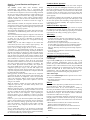
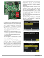
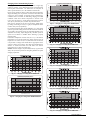
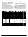
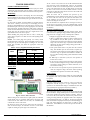
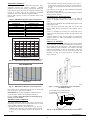
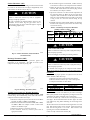
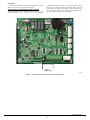
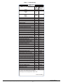
Temperature Thermistors Thermistors are electronic devices which sense temperature. As the temperature increases, the resistance decreases. 10Kohm thermistors are used to sense outdoor air temperature (OAT), coil temperature (OCT) and the suction line temperature (OST) located between the reversing valve and the accumulator. A 50Kohm thermistor is used to sense discharge temperature (ODT). Refer to Table 5 and Fig. 35 and 36 for resistance values versus temperature. Table 5 – 10K/50Kohm Resistance Values vs Temperature 10Kohm _C (_F) TEMPERATURE 25.0 (77.0) 0.0 (32.0) -28.0 (-18.4) RESISTANCE (ohms) 10.0 + / --- 2.3% 32.6 + / --- 3.2% 85.5 + / --- 3.4% 50Kohm 125.0 (257.0) 75.0 (167.0) 25.0 (77.0) 1.7 + / --- 1.6% 7.40 + / --- 2.0% 50.0 + / --- 2.3% THERMISTOR CURVE 90 Failed Thermistor Default Operation Factory defaults have been provided in the event of failure of outdoor air thermistor (OAT) and/or outdoor coil thermistor (OCT). If the OAT sensor should fail, defrost will be initiated based on coil temperature and time. If the OCT sensor should fail, defrost will occur at each time interval during heating operation, but will terminate after 2 minutes. If there is a thermistor out--of--range error, defrost will occur at each time interval during heating operation, but will terminate after 2 minutes. Count the number of short and long flashes to determine the appropriate flash code. Table 7 gives possible causes and actions related to each error. Outdoor Coil Thermistor 80 RESISTANCE (KOHMS) S In heating if the outdoor air sensor indicates 35_F ( 19.4_C) warmer than the coil sensor (or) the outdoor air sensor indicates 10_F ( 5.6_C) cooler than the coil sensor, the sensors are out of range. If the sensors are out of range, the control will flash the appropriate fault code as shown in Table 7. The thermistor comparisons are not performed during low ambient cooling or defrost operation. The outdoor coil thermistor is a 10Kohm resistor used for multiple system operations. It provides the coil/liquid line temperature to the heat pump board and user interface. Low ambient operation, defrost initiation, defrost termination and assistance with OAT temperature measurement of some of the functions. The sensor must be securely mounted to the tube connecting the EXV and distributor. See Fig. 38 for proper placement. See Table 5 for proper resistances. 70 60 50 40 30 20 10 0 0 20 40 60 80 TEMPERATURE (DEG. F) 100 120 A91431 Fig. 35 -- 10K Thermistor Resistance Versus Temperature RESISTANCE (KOHMS) 50K THERMISTOR 450 400 350 300 250 200 150 100 50 0 0 20 40 60 80 100 120 TEMPERATURE (°°F) A14302 A14022 Fig. 36 -- 50K Thermistor Resistance Versus Temperature Fig. 37 -- Outdoor Coil Thermistor (OCT) Attachment (On Distributor Tube) If the outdoor air or coil thermistor should fail, the control will flash the appropriate fault code (see Table 7). IMPORTANT: The outdoor air thermistor, coil thermistor and suction thermistor should be factory mounted in the final locations. Check to ensure thermistors are mounted properly (See Fig. 37, 38, 39 and 40). OAT Thermistor must be locked in place with spherical nib end facing towards the front of the control box Thermistor Sensor Comparison The control continuously monitors and compares the outdoor air temperature sensor and outdoor coil temperature sensor to ensure proper operating conditions. The comparison is: S In cooling if the outdoor air sensor indicates 10_F ( 5.6_C) warmer than the coil sensor (or) the outdoor air sensor indicates 25_F ( 15_C) cooler than the coil sensor, the sensors are out of range. A11142 Fig. 38 -- OAT Thermistor Location (Bottom of Control Box) Catalog No: II288B--- 05 Manufacturer reserves the right to change, at any time, specifications and designs without notice and without obligations. 18 Replaces: II288B--- 04