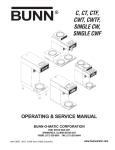
1
BUNN ® CDS-2 CDS-3 OPERATING & SERVICE MANUAL BUNN-O-MATIC CORPORATION POST OFFICE BOX 3227 SPRINGFIELD, ILLINOIS 62708-3227 PHONE: (217) 529-6601 FAX: (217) 529-6644 27646.0000L 06/01 ©1997 Bunn-O-Matic Corporation www.bunnomatic.com INTRODUCTION This equipment dispenses granita-type and cold liquid drinks on demand from separate hoppers. Operating controls are accessible only to key operators. CONTENTS Introduction & Warranty .................................................................................... 2 User Notices ...................................................................................................... 3 Site Preparation, Electrical Requirements & Initial Setup ................................. 5 Operating Controls............................................................................................. 8 Using the Dispenser & Recommendations ...................................................... 10 Recommended Cleaning .................................................................................. 12 Lubrication ...................................................................................................... 13 Faucet Handles ................................................................................................ 14 Auger Assembly............................................................................................... 15 Troubleshooting ............................................................................................... 16 Service............................................................................................................. 21 Refrigerant Flow Diagrams .............................................................................. 51 Schematic Wiring Diagrams ............................................................................ 54 WARRANTY Bunn-O-Matic Corp. (“Bunn”) warrants the equipment manufactured by it to be commercially free from defects in material and workmanship existing at the time of manufacture and appearing within one year from the date of installation. In addition: 1.) Bunn warrants electronic circuit and/or control boards to be commercially free from defects in material and workmanship for three years from the date of installation. 2.) Bunn warrants the compressor on refrigeration equipment to be commercially free from defects in material and workmanship for two years from the date of installation. 3.) Bunn warrants that the grinding burrs on coffee grinding equipment will grind coffee to meet original factory screen sieve analysis for three years from date of installation or for 30,000 pounds of coffee, whichever comes first. This warranty does not apply to any equipment, component or part that was not manufactured by Bunn or that, in Bunn’s judgement, has been affected by misuse, neglect, alteration, improper installation or operation, improper maintenance or repair, damage or casualty. THE FOREGOING WARRANTY IS EXCLUSIVE AND IS IN LIEU OF ANY OTHER WARRANTY, WRITTEN OR ORAL, EXPRESS OR IMPLIED, INCLUDING, BUT NOT LIMITED TO, ANY IMPLIED WARRANTY OF EITHER MERCHANTABILITY OR FITNESS FOR A PARTICULAR PURPOSE. The agents, dealers or employees of Bunn are not authorized to make modifications to this warranty or to make additional warranties that are binding on Bunn. Accordingly, statements by such individuals, whether oral or written, do not constitute warranties and should not be relied upon. The Buyer shall give Bunn prompt notice of any claim to be made under this warranty by telephone at (217) 529-6601 or by writing to Post Office Box 3227, Springfield, Illinois, 62708-3227. If requested by Bunn, the Buyer shall ship the defective equipment prepaid to an authorized Bunn service location. If Bunn determines, in its sole discretion, that the equipment does not conform to the warranty, Bunn shall repair the equipment with no charge for parts during the warranty period and no charge for labor by a Bunn Authorized Service Representative during the warranty period. If Bunn determines that repair is not feasible, Bunn shall, at its sole option, replace the equipment or refund the purchase price for the equipment. THE BUYER’S REMEDY AGAINST BUNN FOR THE BREACH OF ANY OBLIGATION ARISING OUT OF THE SALE OF THIS EQUIPMENT, WHETHER DERIVED FROM WARRANTY OR OTHERWISE, SHALL BE LIMITED, AS SPECIFIED HEREIN, TO REPAIR OR, AT BUNN’S SOLE OPTION, REPLACEMENT OR REFUND. In no event shall Bunn be liable for any other damage or loss, including, but not limited to, lost profits, lost sales, loss of use of equipment, claims of Buyer’s customers, cost of capital, cost of down time, cost of substitute equipment, facilities or services, or any other special, incidental or consequential damages. 2 27646 060401 USER NOTICES Carefully read and follow all notices on the equipment and in this manual. They were written for your protection. All notices are to be kept in good condition. Replace any unreadable or damaged labels. CHARGE Type R22, Amount 8.4 oz Design Pressures: High 210 Low 32 27442.0000 12559.0003 28720.0000 00986.0002 27443.0000 3 27646 022500 USER NOTICES (CONT.) AFTER CLEANING & BEFORE REASSEMBLY 1. Apply lubricant* on lip of auger seal where contact is made with cooling drum. 2. Apply lubricant* on outside surface of cooling drum seal or inside bore of hopper. 3. Apply lubricant* over o-rings on faucet spool before inserting into faucet housing. * Refer to product literature for Bunn approved lubricant. 2 1 CHARGE Type R22, Amount 8.4 oz Design Pressures: High 210 Low 32 27444.0000 (CDS-2 Only) CHARGE Type R404A, Amount 9.5 oz(269g) Design Pressures: High 215 Low 40 29373.00000 (CDSA-2 Only) 3 LUBRICATION 27664.0000D 5/97 © 1996 BUNN-O-MATIC CORPORATION 27664.0000 CHARGE Type R404A, Amount 25 oz Design Pressures: High 320 Low 44 28519.0000 (CDS-3 Prior to S/N CDS0019500) CHARGE Type R404A, Amount 22 oz Design Pressures: High 380 Low 52 29424.0000 (CDS-3 S/N CDS0019500 - UP) 4 27646 022500 SITE PREPARATION These dispensers are very heavy. Place them on a sturdy counter or shelf capable of supporting at least 180 lbs for the CDS2 and 250 lbs for the CDS3. They are for indoor use only. The dispenser must have at least four inches of space behind it. This space is needed for airflow, air filter removal, and cleaning. Minimal clearance is required between the dispenser sides and the wall or another appliance. The dispenser performs better if not placed near any heating appliance. Leave some space so the dispenser can be moved for cleaning. ELECTRICAL REQUIREMENTS CAUTION – Improper electrical installation will damage components. An electrician must provide electrical service as specified below. Model CDS-2, This dispenser has an attached cordset and requires a 2-wire, grounded, individual branch circuit rated 120 volts ac, 15 amp, single phase, 60 Hz. The mating connector must be a NEMA 5-15R. (Refer to the dataplate for exact electrical requirements.) Model CDSA-2, This dispenser has an attached cordset and requires a 2-wire, grounded, individual branch circuit rated 230 volts ac, 10 amp, single phase, 50 Hz. The mating connector must be a NEMA 5-15R. (Refer to the dataplate for exact electrical requirements.) Model CDS-3, This dispenser has an attached cordset and requires a 2-wire, grounded, individual branch circuit rated 120 volts ac, 20 amp, single phase, 60 Hz. The mating connector must be a NEMA 5-20R. (Refer to the dataplate for exact electrical requirements.) Model CDSA-3, This dispenser has an attached cordset and requires a 2-wire, grounded, individual branch circuit rated 230 volts ac, 15 amp, single phase, 50 Hz. The mating connector must be a NEMA 5-20R. (Refer to the dataplate for exact electrical requirements.) NOTE – Bunn-O-Matic does not recommend the use of any extension cord with these dispensers. 5 27646 122200 INITIAL SETUP CAUTION – The dispenser is very heavy! Use care when lifting or moving it. Use at least two people to lift or move the dispenser. 1. Set the dispenser on the counter where it will be used. The CDS-3 dispenser requires a minimum of 6.0" air clearance on both sides and at the rear of the dispenser. For optimum performance, do not let warm air from surrounding machines blow on the CDS-3 and DO NOT REMOVE VINYL DEFLECTOR. NOTE – The dispenser should be level or slightly lower in front for proper operation. 6.0" MIN. 6.0" MIN. 6.0" MIN. Vinyl Deflector DO NOT REMOVE 2. Remove all shipping material, including the compressor support eye-bolts, the cooling drum supports, the “Do Not Lift Here” signs from the cooling drums, and the “Rinse Before Using” signs from each hopper. NOTE – Use BOM M2550.0000 lubricant where specified. 3. Squeeze some lubricant into 4. hand. Apply a thin film of lubricant to 5. each cooling drum seal. Install the seal over the flange at the rear of each cooling drum as shown. 6. Press the seals firmly into 7. place. Apply a thin film of lubricant to 8. the inside of each auger shaft seal. Install the seals on the auger shafts. Wipe the cooling drums to remove any lubricant. 6 27646 022500 INITIAL SETUP (CONT.) 9. Align the auger shaft with the 10. Thoroughly rinse the hoppers 11. Set the lids on the hoppers. and install them over the coolflat fin of the auger. Push the Slide front-to-back or lift off for ing drums with augers. Slide augers as far as they will go and filling. them into place and push them rotate them so the flat fins are down as far as they will go. pointing up. As much as possible, keep lubricant from the inside of the hoppers. The cleaner you keep the food zone, the cleaner the product you’ll serve the customer. APPROXIMATELY .25" 12. Plug in the hopper lid lamp 13. (CDS-2 only) Assemble the drip cables. tray. 14. (CDS-3 only) Loosen the two front legs by turning counterclockwise to gain approximately .25" clearance. Install the slots of the support bracket over threaded studs of the legs as shown in illustration. Tighten the legs by turning clockwise to secure the bracket in place. 15. (CDS-3 only) Install the drip tray. 7 27646 022500 OPERATING CONTROLS (CDS-3 Controls Illustrated) ICE/OFF/NO-ICE SWITCHES ICE CONTROLS Controls the consistency of the ice in the hoppers ICE – This is the normal operating position. Freezes when the DAY/NIGHT switch is in the left “DAY” po- and maintains the ice in the selected hopper to the consition and the ICE/OFF/NO-ICE switch is in the left sistency set with the ICE control(s) when in the left “ICE” position. “ICE” position. OFF – Provides no cooling to the selected hopTurn this control clockwise to produce a per when in the center “OFF” position. coarser ice or counterclockwise to produce a finer ice. (The dispenser is set to deliver NO-ICE – Maintains cooling yet allows any ice LEFT RIGHT ICE ICE satisfactory ice at a 1:00 setting.) in the selected hopper to naturally thaw when CENTER ICE RIGHT in the right “NO-ICE” position. D COL ER 4 3 D COL ER 4 3 D COL ER 4 3 5 2 1 6 5 2 1 AUGER SWITCHES ”—” – This is the normal operating position. Energizes the auger motor when in the right position. The dispenser will cool to the ice consistency or liquid temperature presets only with the switch in the right position. “o” – Removes power from the auger motor when in the left position. AUGER 5 2 1 6 6 ICE OFF ICE DAY/NIGHT SWITCH DAY – This is the normal operating position. ICE ICE AUGER The hoppers’ display lights will glow and the OFF LEFT electronic controls will maintain ice when the switch is in the left “DAY” position, the indiICE ICE AUGER OFF vidual hoppers’ ICE/OFF/NO-ICE switches are in the left “ICE” position, and the individual hoppers’ AUGER switches are in the right “— OFF ON DAY NIGHT ” position. NIGHT – Use this position at night. The hopPOWER OFF/ON SWITCH pers’ display lights will be out yet the liquid ON – This is the normal operating position. The diswill be kept cold in all hoppers when this switch is in the penser is electrically energized when the switch is in right “NIGHT” position and the AUGER switches are in the right “ON” position. NOTE – The compressor will the right “—”position. start after a 3 minute 20 second delay on the CDS-2 and a 6 minute 30 second delay on the CDS-3. NOTE: When Day/Night Timer is used, the Day/Night OFF – All electrical components of the dispenser are Switch in the control drawer must be kept in the “DAY” without power when the switch is in the left “OFF” position. position. CENTER POWER POWER INDICATOR (Located on the front of the drawer) Glows to show that the POWER OFF/ON Switch is in the right “ON” position. STATUS INDICATORS The electronic controls continuously diagnose the operational status of the dispenser and indicate as listed: FLASHING 50% ON / 50% OFF – Glows while preparing for coolant to flow to the selected hopper. (Flashes for 10seconds, then glows steady for two minutes.) STEADY GLOW – Glows for two minutes before coolant flows to the selected hopper, then continues to glow while coolant flows. The electronics also sense and indicate error conditions in the dispenser as listed: ONE FLASH EVERY FOUR SECONDS – Cooling is needed by the selected hopper, but the auger isn’t turning. Try placing the AUGER switch for the selected hopper in the right “—” position. 8 27646 022500 OPERATING CONTROLS (Cont.) TWO FLASHES EVERY FOUR SECONDS – A temperature error is being sensed. Call Bunn-O-Matic for Support. THREE QUICK FLASHES – Low auger torque is being sensed. Call Bunn-O-Matic for Support. FOUR QUICK FLASHES – High auger torque is being sensed. Call Bunn-O-Matic for Support. DAY/NIGHT TIMER The quartz driven timer offers 24-hour programming with 96 actuators that operate in 15-minute increments. All actuators can be individually set to the inside or outside position. The timer is located behind the right side panel. SETTING TIME 1. Locate marker on the inner (stationary) dial that points to outer dial. The marker is at approximately the two O’clock position. 2. Turn outer dial clockwise until the marker is pointing to the correct time. The clock hands will turn with the outer dial indicating the same time as the marker. NOTE - the outer dial has AM and PM settings. SETTING NIGHT TIME MODE 1. Locate the actuators positioned around the outer dial. Inward position indicates day time mode and outer position indicates night time mode. 2. Determine the desired times that night time mode is to begin and end. 3. Position all actuators between begin and end times in the outer position. P1948 Shown in “Night Time” Mode EXAMPLE: Night Time Mode is 11:00 PM - 7:00 AM Place the actuator at 11:00 PM to the outside position. Continue placing actuators to the outside position counterclock wise around the dial to 7:00 AM. All actuators from 7:00 AM to 11:00 PM must be in the inside position. NOTE: For Day/Night Timer to operate, the Day/Night Switch in the control drawer must be kept in the “DAY” position. P1947 Shown in “Day Time” Mode 9 27646 022500 USING THE DISPENSER FOR GRANITA-TYPE PRODUCTS 1. 2. 3. 4. Slide the lid for the selected hopper to the front or back to gain access to the hopper. Place the premixed liquid product in the selected hopper. Simply press all switches to the center of the control drawer for granita products. a. Place the POWER OFF/ON switch in the right “ON” position. b. Place the auger switch for the selected hopper in the right “—” position. c. Place the DAY/NIGHT switch in the left “DAY” position. d. Place the ICE/OFF/NO-ICE switch in the left “ICE” position. Wait for the liquid to freeze to the desired consistency. HINTS – Bunn-O-Matic recommends that the product in the dispenser be thawed each day, usually overnight. The ice granules get too large and a consistent product is difficult to maintain if left frozen for an extended period of time. Place the DAY/NIGHT switch in the right “NIGHT” position for a few hours each night. Then return it to the left “DAY” position when the product has thawed sufficiently. You’ll know it is in the night position because the hopper lid lights are out. USING THE DISPENSER FOR COLD LIQUID PRODUCTS 1. 2. 3. 4. Slide the lid for the selected hopper to the front or back to gain access to the hopper. Place the premixed liquid product in the selected hopper. Simply place all switches to the center of the control drawer except the ICE/OFF/NO-ICE switch. a. Place the POWER OFF/ON switch in the right “ON” position. b. Place the auger switch for the selected hopper in the right “—” position. c. Place the DAY/NIGHT switch in the left “DAY” position. d. Place the ICE/OFF/NO-ICE switch in the right “NO-ICE” position. Wait for the liquid to cool. 10 27646 022500 OTHER RECOMMENDATIONS FOR YOUR DISPENSER • Whether liquid concentrate or granulated powder, all product must be thoroughly mixed BEFORE adding it to the hoppers. • For best results with granita-type products, use only products with an apparent brix of 12 or higher. Some products may work with an apparent brix as low as 9. Your experimentation with other products will be the best guide in this area. Keep the premixed liquid product refrigerated. This reduces cooling/freezing time in the dispenser. Keep the hoppers topped-off during peak serving periods. Add premixed liquid product as it is dispensed. This reduces the cooling/freezing time and assures you of always having product ready to dispense. Keep the product level in the hoppers higher than the auger. Air will become entrapped in the mixture resulting in a clouded foamy consistency. You may find it beneficial to turn down the ice controls to keep the ice granules from growing too large. Refer to the operating controls on page 1-6. Some products freeze at a lower temperature than others. You may notice frost or ice on the hoppers. This is normal and should not be a concern. Humidity in the air may cause sweating on the outside surfaces of the hoppers. This is to be expected and should not be a concern. The drip trays beneath the hoppers will capture this and cause it to flow to the lower drip tray for disposal. Some noises are to be expected during normal operation of the dispenser. By becoming familiar with the noises made during normal operation, you will be better able to listen for problems. • • • • • • • 11 27646 022500 RECOMMENDED DAILY CLEANING (SUGAR & ALCOHOL PRODUCTS!) NOTE – Close the control drawer before proceeding. 1. Empty all product from the hoppers. 2. The driptray should be cleaned as needed for proper presentation of the product. 3. Mix a packet of Kay-5 Sanitizer diluted with two-gallons of warm (120° F) water for each hopper. 4. Open the lids and add the solution. 5. Allow the solution to work for about five minutes with the dispenser on the ”NIGHT” position. 6. Drain the sanitizing solution from the hoppers and completely rinse each with clean water. 7. Wash the underside of hopper covers or powder autofill dispensers with hot water and a mild detergent solution. Rinse all surfaces and apply some commercial sanitizing agent. Do not immerse hopper lids. NOTE – The hoppers and augers should be removed and disassembled for cleaning at least once a week using the procedure below. RECOMMENDED WEEKLY CLEANING (SUGAR & ALCOHOL BASED PRODUCTS!) RECOMMENDED DAILY CLEANING (DAIRY PRODUCTS!) NOTE – Close the control drawer before proceeding. 1. Empty all product from the hoppers. Disconnect the hopper lid cords and remove the lids. 2. Lift the hopper up slightly, then 3. use a hard plastic utensil to pry it up. Pull forward to remove. Pull the auger from the cooling 4. drum. Remove the auger shaft seal from the front of the cooling drum and the cooling drum seal from the rear of the drum. Disassemble the auger for cleaning by spreading apart the latches and removing each piece. 5. Spread the sides of the dispense 6. handle and pull it off to remove the faucet pieces. Push the metal pin out through 7. the faucet. Unscrew the plastic cap, and push the faucet spool and spring out the bottom. Squeeze the O-rings to free them from the grooves in the faucet spool. 8. Roll the O-rings off of the faucet 9. spool. Remove the black plug from the 10. Pull down, then out on the air faucet spool for cleaning. Do not filter at the rear of the dispenser. use tools to remove this. 12 27646 022500 RECOMMENDED WEEKLY CLEANING (CONT.) 11. Wash all components with a wash cloth in mild hot water and detergent solution. Do not immerse hopper lids. 12. Wash the drums, hopper drip trays, top covers, and outer enclosure using a clean wash cloth that has been dampened in a mild solution of detergent and hot water. 13. Thoroughly rinse all surfaces with a clean wash cloth that has been dampened with hot water. Wipe dry with a clean dry wash cloth before reassembling the dispenser. 14. Remove the lower drip tray assembly. Wash and thoroughly rinse all pieces before reinstallation. NOTE – Although most parts are dishwasher safe, they may be affected by some commercial sanitizing agents. Do not place the hopper nor hopper lids in a dishwasher. LUBRICATION NOTE – Use BOM M2550.0000 lubricant where specified. 1. Squeeze some lubricant into 2. hand. Apply a thin film of lubricant to 3. each cooling drum seal. Install the seals over the flange at the rear of the cooling drums as shown. 4. Press the seals firmly into 5. place. Apply a thin film of lubricant to 6. the inside of each auger shaft seal. Install the seals on the auger shafts. Wipe the cooling drums to remove any excess lubricant. 7. Align the auger shafts with the 8. flat fin of the augers. Push the augers as far as they will go and rotate them so the flat fins are pointing up. Thoroughly rinse the hoppers 9. and install them over the cooling drums with augers. Slide them into place and push them down as far as they will go. As much as possible, keep lubricant from the inside of the hoppers. The cleaner you keep the food zone, the cleaner the product you’ll serve the customer. Set the lids on the hoppers. 13 27646 022500 LUBRICATION (cont.) 10. Reinstall the black plug into the 11. Apply a thin film of lubricant to 12. Slide the O-rings onto the faucet spool. Do not lubricate each faucet spool O-ring. spools. the plug. 13. Reinstall the plastic caps, 14. Plug in the hopper lid lamp 15. Assemble the drip tray. springs, spools, and metal pins. cables. Spread the dispense handles and reinstall them. NOTE – When reinstalling the fau- NOTE – The faucet spool plugs, faucet O-rings, cooling drum hopper seals, cet caps, they MUST be twisted and auger shaft seals are to be replaced whenever they appear worn as far as they will go. (Past the or damaged. Bunn-O-Matic recommends their replacement at least point where it clicks.) every six-months. Refer to page 24 for replacement instructions. FAUCET HANDLES Dispensing from the hoppers will occur when the faucet handles are installed with the handles in the upright position. (shown, left hopper) Dispensing from the hoppers will not occur when the handles are installed upside-down. (shown, right hopper) You may consider this handle position when the product in the hoppers is not yet ready to serve. Just spread the handles or disassemble them as shown, and install them upside down. DISASSEMBLY 1. Unscrew the balls from the handle assemblies. Turn them in a counterclockwise direction until they are no longer attached to the handles. 2. Remove the metal sleeves from the assemblies. 3. Separate the two halves of the handles and remove them from the faucet bodies. ASSEMBLY 1. Place the two halves of the handles on the faucet bodies. Check that the faucet dowel pins are in place all the way through the faucet bodies. The dowel pins must be captured by the keyholes in the handle halves. 2. Place the metal sleeves over the threads and install the balls by turning them in a clockwise direction. 14 27646 122200 AUGER ASSEMBLY & DISASSEMBLY (EARLY AUGERS ONLY) The augers may look intimidating at first glance. But there are really just a few pieces snapped together. Please familiarize yourself with this procedure. It’ll make cleaning and routine maintenance easier. The augers should be taken apart for cleaning and then reassembled for use. Short Auger Latch Auger Sections (3 req’d.) Long Auger Latch Auger Nose ASSEMBLY 1. Snap one of the auger sections to the long auger latch. 2. 3. 4. Snap the auger nose onto the last section installed. 5. With the long auger latch on top, place the short auger latch inside the augers and snap it onto the assembly. Snap another auger section in place. Snap the third auger section in place. DISASSEMBLY 1. Firmly pull the auger section connections apart at each slot in the long auger latch. 2. Firmly pull the connection between the auger section and auger nose apart. 3. Separate the slots in the short auger latch as you remove the auger sections. 15 27646 022500 TROUBLESHOOTING A troubleshooting guide is provided to suggest probable causes and remedies for the most likely problems encountered. If the problem remains after exhausting the troubleshooting steps, contact the Bunn-O-Matic Technical Service Department. • • • • Inspection, testing, and repair of electrical equipment should be performed only by qualified service personnel. All electronic components have 120 volt ac and/or low voltage dc potential on their terminals. Shorting of terminals or the application of external voltages may result in board failure. Intermittent operation of electronic circuit boards is unlikely. Board failure will normally be permanent. If an intermittent condition is encountered, the cause will likely be a switch contact or a loose connection at a terminal or crimp. Keep away from combustibles. WARNING – • • • • Exercise extreme caution when servicing electrical equipment. Unplug the dispenser when servicing, except when electrical tests are specified. Follow recommended service procedures Replace all protective shields or safety notices PROBLEM PROBABLE CAUSE 1. No power or incorrect voltage to Doesn't work (Switches do nothing, auger not the dispenser turning, no hopper lid lights, no fan, no compressor sound.) 2. ON/OFF Switch REMEDY (A) Check for proper voltage at the wall outlet. (B) Check circuit breakers or fuses. (A) The ON/OFF Switch must be in the "ON" position. (B) Refer to Service - Dispenser ON/ OFF Switch for testing procedures. See page 37. Hopper Lid Lights not on 1. DAY/NIGHT Switch (A) The DAY/NIGHT Switch must be in the "DAY" position. (B) Refer to Service - DAY/NIGHT Switch for testing procedures. See page 36. 2. Lamp Cord Assembly (A) The lamp cord must be plugged into the lamp cord connector. (B) Refer to Service - Lamp Cord Assembly for testing procedures. See page 42. 16 27646 122200 TROUBLESHOOTING (cont.) PROBLEM PROBABLE CAUSE Hopper Display Lights not on (cont.) 3. Circuit Breaker REMEDY (A) The circuit breaker must not be tripped. (B) Refer to Service - Circuit Breaker for testing procedures. See page 27. Auger Motor won't turn 4. Lamps Remove the lamps and check for continuity across the base and tip. Replace if necessary. 5.Transformer Refer to Service - Transformer for testing procedures. See page 49. 6. Lamp Holder/Socket Assy Refer to Service - Lamp Holder/ Socket Assembly for testing procedures. See page 44. 1. Auger ON/OFF Switch(es) (A) The auger switch must be in the "ON" position. (B) Refer to Service - Auger ON/OFF Switch(es) for testing procedures. See page 26. 2. Auger Motor Capacitor(s) Refer to Service - Auger Motor Capacitor(s) for testing procedures. See page 23. 3. Auger Motor(s) Refer to Service - Auger Motor(s) for testing procedures. See page 22. Fan not spinning (With adjustment 1. Fan Motor Board L.E.D.s ON steadily for two minutes) Refer to Service - Fan Motor for testing procedures. See page 39. Fan spins after compressor shuts 1. Time Delay off The fan motor will run for approximately two minutes after compressor shuts off. 17 27646 122200 TROUBLESHOOTING (cont.) PROBLEM PROBABLE CAUSE REMEDY The dispenser must not be connected with an extension cord. Refer to Electrical Requirements. Compressor not running 1. Power cord (With Adjustment Board L.E.D.s ON steadily for two minutes) 2. Fuse Refer to Service - Fuse and Fuse Holder for testing procedures. See page 40. 3. Contactor Refer to Service - Contactor for testing procedures. See page 34. 4. Electronic Control Refer to Service - Electronic Control for testing procedures. See page 38. 5. Compressor Start Relay Refer to Service - Compressor Start Relay for testing procedures. See page 28 (CDS-2) or 31 (CDS-3). 6. Thermal Overload Protector Refer to Service - Compressor Thermal Overload Protector for testing procedures. See page 28 (CDS-2) or 31 (CDS-3). 7. Compressor Start Capacitor Refer to Service - Compressor Start Capacitor for testing procedures. See page 28 (CDS-2) or 31 (CDS-3). 8. Compressor Refer to Service - Compressor for testing procedures. See page 28 (CDS-2) or 31 (CDS-3). Compressor runs but will not cool 1. Auger not turning (With adjustment Board L.E.D.s flashing once every 4 seconds) Refer to Troubleshooting - Auger Motor Won't Turn on previous page. Compressor runs but will not cool 1. Temperature Sensor Assembly (With adjustment Board L.E.D.s flashing twice every 4 seconds) Refer to Service - Temperature Sensor Assembly for testing procedures. See page 47. Compressor runs but will not cool 1. Torque Sensor Circuit Board (With adjustment Board L.E.D.s flashing 3, or 4 times every 4 seconds) Refer to Service - Torque Sensor Circuit Board for testing procedures. See page 48. 18 27646 122200 TROUBLESHOOTING (cont.) PROBLEM PROBABLE CAUSE REMEDY Compressor runs but will not cool 2. Air Filter or Condenser (With adjustment Board L.E.D.s flashing 3, or 4 times every 4 seconds) (cont.) 3. Refrigerant The air filter and condenser MUST be cleaned regularly. Any dust buildup will affect cooling ability. Product Won't Freeze (A) The DAY/NIGHT Switch must be in the "DAY" position. 1. DAY/NIGHT Switch Have a qualified service person check the refrigerant charge. (B) Refer to Service - DAY/NIGHT Switch for testing procedures. See page 36. 2. Sugar content of product Bunn recommends the use of products with an apparent brix of 12 or higher. 3. Voltage Divider Refer to Service - Voltage Divider for testing procedures. See page 50. Product freezes but ice granules are 1. Ice adjustment too fine or too large Turn the Ice control for the desired hopper a small amount clockwise to increase the ice granule size or counterclockwise to decrease the ice granule size. 2. Sugar content of product Dispenser is making unusual noises. 1. Lubrication (Some noises are a normal occurance with this type of device. You need to become familiar with those that are normal, to determine when they have 2. Cooling Drum(s) become unusual.) 19 Adjust the sugar content of the product. Increasing the apparent brix results in finer ice granules. Decreasing the apparent brix results in larger ice granules. Always lubricate the dispenser as directed in this manual before reassembling and using the dispenser. Use the cooling drum support to determine that the auger shaft is still the proper distance from the hopper drip tray. The cooling drum may be gently lifted to return it to the necessary horizontal position. Refer to Service - Cooling Drum Alignment. See page 35. 27646 122200 TROUBLESHOOTING (cont.) PROBLEM PROBABLE CAUSE REMEDY Dispenser is making unusual noises. 3. Fan Motor (Some noises are a normal occurance with this type of device. You need to become familiar with those that are normal, to determine when they have become unusual.) 4. Auger Motor(s) (cont.) Remove the air filter at the rear of the dispenser and listen for fan motor noise. Replace the motor if excessively noisy. Product is leaking into the inside of 1. Worn Shaft the drum. Replace Shaft. Refer to Service Auger Shaft Assembly. See page 24. 2. Worn Seals Replace Cooling Drum Seal. Refer to Service - Auger Shaft Assembly. See page 24. 20 Place the Auger switches in the "ON" position and the ICE/OFF/NO-ICE switches in the “OFF” position. Listen for auger motor noise. Replace the motor if excessively noisy. 27646 122200 SERVICE This section provides procedures for testing and replacing various major components used in this dispenser should service become necessary. Refer to Troubleshooting for assistance in determining the cause of any problem. WARNING - Inspection, testing, and repair of electrical equipment should be performed only by qualified service personnel. The dispenser should be disconnected from the power source when servicing, except when electrical tests are required and the test procedure specifically states to connect the dispenser to the power source. COMPONENT ACCESS WARNING - Disconnect the dispenser from the power source before the removal of any panel or the replacement of any component. All components are accessible by removal of the auger motor cover, lower drip tray, front cover and the left and right side covers. Refer to the contents listing for component location. Contents Auger Motors .................................................................................................. 22 Auger Motor Capacitors ................................................................................... 23 Auger Shaft Assembly ..................................................................................... 24 Auger ON/OFF Switches ................................................................................... 26 Circuit Breaker ................................................................................................. 27 Compressor (CDS-2) ....................................................................................... 28 (Compressor, Compressor Start Capacitor, Compressor Start Relay, Thermal Overload Protector) Compressor (CDS-3) ....................................................................................... 31 (Compressor, Compressor Start Capacitor, Compressor Start Relay, Thermal Overload Protector) Contactor ......................................................................................................... 34 Cooling Drum Alignment ................................................................................. 35 Day/Night Switch ............................................................................................. 36 Dispenser ON/OFF Switch ................................................................................ 37 Electronic Control ............................................................................................ 38 Fan ................................................................................................................... 39 Fuse and Fuse Holder ...................................................................................... 40 ICE/OFF/NO ICE Switch .................................................................................... 41 Lamp Cord Assembly ...................................................................................... 42 Lamp Cord Connector...................................................................................... 43 Lamp Holder/Socket Assembly ........................................................................ 44 L.E.D./Adjustment Board ................................................................................. 45 Solenoids ......................................................................................................... 46 Temperature Sensor Assembly ........................................................................ 47 Torque Sensor Circuit Board ............................................................................ 48 Transformer ..................................................................................................... 49 Voltage Divider ................................................................................................ 50 Coolant Schematics ......................................................................................... 51 Electrical Schematics ....................................................................................... 54 21 27646 122200 SERVICE(CONT.) AUGER MOTORS FIG. 1 AUGER MOTORS aside with wires attached. 4. Disconnect the auger motor terminal from the terminal on the main wiring harness. 5. Remove the three remaining #8 locking screws securing the auger motor mounting bracket to cooling drum mounting bracket. 6. Remove motor with mounting bracket, drip tray, split pin and torsion spring bearing as an assembly. NOTE: When removing or installing the motor be sure the split pin in the motor shaft is turned to a position that will clear the torque sensor circuit board. 7. Install new motor with mounting bracket, drip tray, split pin and torsion spring bearing using three #8 locking screws onto the cooling drum bracket. 8. Install the auger motor capacitor on the lower right side of the auger mounting bracket, using the remaining #8 locking screw. 9. Connect the auger motor terminal to the terminal on the main wiring harness. 10. Refer to Fig. 2 when reconnecting the wires. P1341 Location The auger motors are located at the upper rear of the dispenser chassis inside the auger motor covers. Test Procedures 1. Disconnect the dispenser from the power source. 2. Disconnect the wires from the motor to be tested. 3. With a voltmeter, check the voltage across the white/brown wire for the left motor, the white/blue wire for the right motor, or the grey wire for the center motor and the white/black wire. Place the appropriate auger switch in the “-” (“ON”) position. Connect the dispenser to the power supply. The indication must be: a) 120 volts ac for 120 volt models. b) 230 volts ac for 230 volt models. 4. Disconnect the dispenser from the power supply. If voltage is present as described, replace the motor. If voltage is not present as described, refer to the Wiring Diagram and check the dispenser wiring harness. FIG. 2 AUGER MOTOR TERMINALS P1321 Removal and Replacement 1. Remove the two #8 locking screws securing the auger motor cover to the cooling drum mount assembly. 2. Remove the cover and set aside for reassembly. 3. Remove the #8 locking screw on the lower right side of the auger motor mounting bracket securing the auger motor run capacitor. Set capacitor 22 27646 022500 SERVICE (CONT.) AUGER MOTOR CAPACITOR Removal and Replacement 1. Remove the two #8 locking screws securing the auger motor cover to the cooling drum mount assy. 2. Remove the cover and set aside for reassembly. 3. Disconnect the wires from the auger motor capacitor terminals. 4. Remove the #8 locking screw on the lower right side of the auger motor mounting bracket securing the auger motor capacitor. 5. Install a new capacitor on the lower right side of the auger mounting bracket and secure with a #8 locking screw. 6. Reconnect the wires to the capacitor terminals. 7. Refer to Fig. 4 when reconnecting the wires. FIG. 3 AUGER MOTOR CAPACITORS P1341 Location: The auger motor capacitors are located on the lower right side of the auger motor mounting bracket inside the auger motor covers. Test Procedures: 1. Disconnect the dispenser from the power source. 2. Disconnect the wires from the capacitor to be tested. 3 With a voltmeter, check for voltage across the white/blue wire on the right capacitor, the white / brown wire on the left capacitor, or the grey wire on the center capacitor and the white/black wire on the auger motor terminal. Place the appropriate auger switch in the “-” (“ON”) position. Connect the dispenser to the power source.The indication must be: a) 120 volts ac for 120 volt models. b) 230 volts ac for 230 volt models. 4. Disconnect the dispenser from the power source. If voltage is present as described, proceed to #5. If voltage is not present as described, refer to the Wiring Diagram and the dispenser wiring harness. 5. Check for continuity across the auger motor capacitor terminals. If continuity is present as described, reconnect the wires to the auger motor capacitor. If continuity is not present as described, replace the auger motor capacitor. P1324 FIG. 4 AUGER MOTOR CAPACITOR TERMINALS 23 27646 022500 SERVICE (cont.) 7. Pull the auger shaft assembly straight out of cooling drum. Inspect the shaft for abnormal wear or scoring. 8. From the front of dispenser, remove the seal and blue bushing from cooling drum and discard them. 9. Clean seal and busing surfaces of the cooling drum very thoroughly. All old lubricant must be removed. 10. Refer to Fig 6A and slip new blue bushing into cooling drum. Lightly lube I.D. of bushing with #M2550.0000 “Lubri-film” provided in Kit #28106.0000 (CDS-2) or #28106.0001 (CDS-3). Do not use anything such as a cotton swab that might leave lint or unravel. DON NOT GET ANY LUBE ON THE SEAL COUNTERBORE SURFACE. 11. Lightly lube I.D. of new cooling drum seal with #M2550.0000, provided in kit. Use care not to get any lube on O.D. of seal. Place seal on insertion tool #28395.0000, as shown in Fig. 6B. Make sure open face of seal is toward cooling drum. 12. Push seal into bore until it is firmly seated; remove tool. 13. Clean the auger shaft assembly, then wipe a small amount of #M2550.0000 “Lubri-film” (provided in kit) over the first two inches of the front end of the shaft. 14. Place a small amount of #29563.0000 “Krytox” lubricant (provided in kit in a plastic cap) on the end of the motor shaft (about 1 1/2") and a thin film in the groove. Install auger shaft assembly onto the motor shaft. See Fig. 6C. Do not use too much “Krytox” lubricant. AUGER SHAFT ASSEMBLY Auger Shaft Assy Auger Shaft Bushing Cooling Drum Seal Auger Shaft Seal Hopper Drum Seal P1758 FIG. 5 AUGER SHAFT ASSEMBLY Location: The Auger Shaft Assembly is located in each of the cooling drums. Removal and Replacement: 1. Drain, remove and clean hopper; refer to the Recommended Daily Weekly Cleaning Section of this manual, page 12, for proper cleaning procedures. Discard the auger shaft seal, hopper/drum seal and faucet spool o-rings. 2. Remove the #8 locking screws securing auger motor cover to the cooling drum mount assembly; remove cover and set aside for reassembly. 3. Remove the #8 locking screw on the lower right side (viewed from front) of the auger motor mounting bracket securing the auger motor run capacitor. Set capacitor aside with wires attached. 4. Disconnect the auger motor terminal from the terminal on the main wiring harness. 5. Remove the remaining #8 locking screws securing the auger motor mounting bracket to cooling drum mounting bracket. 6. Remove motor with mounting bracket, drip tray (if present) split pin and torsion spring bearing as an assembly. NOTE - This is the only place “Krytox” lubricant is used. 15. Assemble motor/shaft assembly as shown in Fig. 6C, then install assembly into cooling drum. Make sure the pins do not hit the sensor board and cooling drum seal is not dislodged as the shaft passes through. 16. Secure motor and capacitor to the cooling drum mounting bracket. Install rear motor cover. 17. Refer to Initial Setup for hopper assembly and installation procedures. Be sure to use new hopper/ drum seal, auger shaft seal and faucet spool orings when reassembling. NOTE - When removing or installing motor and shaft assemblies, be sure the split pins are turned to a position that will clear the torque sensor circuit board. 24 27646 122200 SERVICE (cont.) AUGER SHAFT ASSEMBLY(cont.) y;À@y;À@ y ; À @ ;;; y ; À @ yy ÀÀ @@ ;; ;;; @@ ÀÀ ;; yy ;;; @@y;À@y;À@ ÀÀ ;; yy ;;; y;À@y;À@ Lube about 1 1/2" of shaft and in the groove with #29563.0000 “Krytox” Lubricant Lightly lube the bushing I.D. with M2550.0000 “LubriFilm” Auger Shaft Assy Do NOT get any Lube on this surface Lube about 2.0" of shaft with #M2550.0000 “Lubrifilm” P1759 P1761 FIG. 6A AUGER SHAFT BUSHING FIG. 6C MOTOR/SHAFT ASSEMBLY Open face of seal away from tool Cooling Drum Seal Seal Insertion Tool P1760 FIG. 6B COOLING DRUM SEAL 25 27646 122200 SERVICE (cont.) AUGER ON/OFF SWITCHES If continuity is present as described, the auger switch is operating properly. If continuity is not present as described, replace the auger switch. FIG. 7 AUGER ON/OFF SWITCHES Removal and Replacement: 1. Pull the dispenser drawer out until the drawer hits the drawer stop. Using a screwdriver gently pry up on the drawer stop and remove the drawer from the dispenser. 2. Remove the four #8-32 locking screws securing the switch panel to the drawer. 3. Lift the switch panel with wires and L.E.D./adjustment board out as an assembly. 4. Turn switch panel over and remove the wires from the auger switch that is to be replaced. 5. Compress the clips on the back of the control panel and gently push switch through the opening. 6. Push the new switch into the opening, with the “o” on the switch to the outside, until the clips snap into position. 7. Reconnect the wires to the switch. Refer to Fig. 8 when reconnecting wires. 8. Position the switch panel inside the drawer and secure with four #8-32 locking screws. 9. Reinstall drawer. P1343 Location: The auger switches are located inside the dispenser drawer. Test Procedures: 1. Disconnect the dispenser from the power source. 2. Disconnect the white/green wire from the switch to be tested and white/black wire from contactor located on the outside bottom of the component bracket . 3. With a voltmeter, check the voltage across the white/green and the white/black wires and the “ON/OFF” switch in the “ON” position. Connect the dispenser to the power source. The indication must be: a) 120 volts ac for 120 volt models. b) 230 volts ac for 230 volt models. 4. Disconnect the dispenser from the power source. If voltage is present as described, reconnect the white/ black wire to the contactor and proceed to #5. If voltage is not present as described, refer to the Wiring Diagram and check the dispenser wiring harness. FIG. 8 AUGER SWITCH TERMINALS P1336 5. Remove the white/blue wire from the right auger switch, the white/brown wire from the left auger switch, or the grey wire from the center auger switch. 6. With the auger switch to be tested in the “ON” position check for continuity across the terminals. Continuity must not be present when the switch is in the “OFF” position. 26 27646 122200 SERVICE (cont.) CIRCUIT BREAKER 5. Push the new circuit breaker into the opening in the component bracket until the clips snap into position. 6. Reconnect the wires to the circuit breaker. 7. Position the component bracket in chassis and secure with four #8-32 locking screws. 8. Refer to Fig. 10 when reconnecting the wires. RED from Transformer R2 2 FIG. 9 CIRCUIT BREAKER P1342 Location: The circuit breaker is located inside the dispenser on the upper left side of the component bracket. RED from Main Harness Test Procedures: 1. Disconnect the dispenser from the power source. 2. Remove the wires from the circuit breaker. 3. Check for continuity between the terminals. Continuity must be present between the terminals. If continuity is present as described the circuit breaker is functioning properly. If continuity is not present as described, press the reset button and repeat step #3, if continuity is not present as described, replace the circuit breaker. P1330 FIG. 10 CIRCUIT BREAKER TERMINALS Removal and Replacement: 1. Remove the four #8-32 locking screws securing the component bracket to the chassis. 2. Tip the top of the component bracket forward far enough to allow access to the rear of the circuit breaker. 3. Remove the wires from the circuit breaker. 4. Compress the clips on the back side of the component bracket and gently push the circuit breaker through the opening in the component bracket. 27 27646 122200 Test Procedures: WARNING: The compressor start capacitor must be properly discharged before proceeding. SERVICE (cont.) COMPRESSOR & COMPONENTS (CDS-2) Compressor Start Relay: Refer to FIG. 12 1. Disconnect the dispenser from the power source. 2. Remove compressor terminal cover retainer (6) and compressor terminal cover (5). 3. Disconnect the black wire from the thermal overload protector (3) and white/black wire from the compressor start relay (1). 4. With a voltmeter, check voltage across the black wire and the white/black wire and the ON/OFF switch in the “ON” position, DAY/NIGHT switch in the “DAY” position and the ICE/OFF/NO ICE switch in the “ICE” position. Connect the dispenser to the power source. The indication must be 120 volts ac for two wire 120 volt models or 230 volts ac for two wire 230 volt models. 5. Disconnect the dispenser from the power source. If voltage is present as described, proceed to #6. If voltage is not present as described, refer to the Wiring Diagram and check the dispenser wiring harness. 6. Disconnect the two black wires from the compressor start capacitor. 7. Remove relay from the compressor. 8. Check for continuity across the upper left terminal and the right pin socket on the rear of the relay. If continuity is present as described, the compressor start relay is operating properly. If continuity is not present as described, replace relay. R2 2 P1342 FIG. 11 COMPRESSOR ASSY Location: The compressor assy is located inside the front of the dispenser chassis. 1 4 R2 2 3 2 5 6 120V COMPRESSORS 4 3 1 5 6 Compressor: 1. With the compressor start relay (1) removed, disconnect the black wire from the compressor. 2. Check for continuity across the terminal on the compressor and the left pin on the compressor. If continuity is present as described, the electrical part of the compressor is operating properly. If continuity is not present as described, replace the compressor. 7 R2 2 P1344 230V COMPRESSORS FIG. 12 COMPRESSOR ELECTRICAL COMPONENTS 1. Compressor Start Relay 2. Overload Protector Retainer 3. Thermal Overload Protector 4. Compressor Start Capacitor 5. Compressor Terminal Cover 6. Compressor Terminal Cover Retainer 7. Compressor Run Capacitor 28 Thermal Overload Protector: 1. Check for continuity across the terminals on the thermal overload protector (3). If continuity is present as described, the thermal overload protector is operating properly. If continuity is not present as described, replace the thermal overload protector. 27646 122200 former and Fig. 22 for contactor. 11. Position the component bracket in the chassis and secure with four #8-32 locking screws. 12. Reconnect tubes from the condenser and the accumulator to the compressor. 13. Evacuate the system. NOTE: When replacing the compressor it is recommended that the dryer also be replaced. 14. Recharge 120V system with 8.4 oz. of Type R22 refrigerant. Design Pressures: High 210 - Low 32 Recharge 230V system with 9.5 oz. of Type 404A refrigerant. Design Pressures: High 215 - Low 40 NOTE: The charging of the system must be done by a licensed refrigeration repair person. SERVICE (cont.) COMPRESSOR & COMPONENTS (CDS-2) (cont.) Compressor Start Capacitor: 1. Check for continuity across the terminals on the compressor start capacitor. If continuity is present as described, the start capacitor is operating properly. If continuity is not present as described, replace the capacitor. NOTE: If all the electrical components are operating properly and the compressor does not operate, there is an internal mechanical problem. Replace the compressor. Removal and Replacement: Compressor Start Capacitor: Refer to FIG. 12 WARNING: The compressor start capacitor must be properly discharged before proceeding. 1. Remove terminal cover retainer (6) and terminal cover (5). Set aside for reassembly. 2. Disconnect the two leads from the capacitor. 3. Pry the end of the capacitor mounting bracket off of the boss on the capacitor and remove the capacitor. 4. Install new capacitor on the capacitor mounting bracket. 5. Refer to Fig. 13 and reconnect the wires to the capacitor. 6. Reinstall terminal cover (5) and cover retainer (6). Compressor Assy: NOTE: Before removal of any refrigeration component the refrigerant in the system must be reclaimed by a licensed refrigeration repair person. 1. Disconnect the tubes from the condenser and the accumulator. 2. Disconnect the compressor wiring harness from the dispenser main wiring harness. 3. Remove the four .25-20 keps nuts and washers securing the compressor to the chassis. Set nuts and washers aside for reassembly. 4. Remove the four #8-32 locking screws securing the component bracket to the dispenser chassis. 5. Disconnect the wires from the circuit breaker, fuse holder, transformer, electronic control and the contactor. 6. Remove component bracket with circuit breaker, fuse holder, transformer, electronic control and contactor as an assembly. Set component bracket and screws aside for reassembly. 7. From the right side of the dispenser lift the compressor assembly over the four studs in the chassis and remove compressor. 8. Install new compressor over the four studs in the dispenser chassis with the fill valve to the left side of the dispenser. 9. Secure compressor to the dispenser chassis using four .25-20 keps nuts and washers. 10. Reconnect the wires to the components on the component bracket and plug the main wiring harness into the electronic control. NOTE: When reconnecting wires refer to Fig. 10 for circuit breaker, Fig. 34 for fuse holder, Fig. 51 for trans- 120V DISPENSERS 230V DISPENSERS P1340 FIG. 13 COMPRESSOR START CAPACITOR TERMINALS 29 27646 122200 Compressor Thermal Overload Protector (230V): Refer to FIG. 12 1. Remove terminal cover retainer (6) and terminal cover (5). 2. Disconnect the black wire from the thermal overload protector. 3. Pull thermal overload protector off of the compressor pin and discard. 4. Push new thermal overload protector onto the compressor pin. 5. Refer to Fig. 15 and reconnect the wire. 6. Reinstall terminal cover (5) and cover retainer (6). SERVICE (cont.) COMPRESSOR & COMPONENTS (CDS-2) (cont.) Compressor Start Relay: Refer to FIG. 12 1. Remove the terminal cover retainer (6) and the terminal cover (5) WARNING: The compressor start capacitor must be properly discharged before proceeding. 2. Disconnect the wires from the compressor start relay. 3. Pull relay (1) off of the compressor pins and discard. 4. Push new relay onto the compressor pins. 5. Refer to Fig. 14 and reconnect the wires. 6. Reinstall terminal cover (5) and cover retainer (6). 120V DISPENSERS 120V DISPENSERS 230V DISPENSERS FIG. 14 COMPRESSOR START RELAY TERMINALS 230V DISPENSERS P1338 Compressor Thermal Overload Protector (120V): Refer to FIG. 12 1. Remove terminal cover retainer (6) and terminal cover (5). 2. Disconnect the wire from thermal overload protector to the compressor and the wire from the compressor wiring harness to the thermal overload protector. 3. Remove overload protector retainer (2) and thermal overload protector (3) as an assembly. 4. Remove retainer (2) from overload protector (3) and discard overload protector. 5. Install retainer (2) on new overload protector (3). 6. Install retainer (2) and overload protector (3) on the compressor terminal bracket. 7. Refer to Fig. 15 and reconnect the thermal overload protector wires. 8. Reinstall terminal cover (5) and cover retainer (6). P1339 FIG. 15 THERMAL OVERLOAD PROTECTOR TERMINALS Compressor Run Capacitor (230V Dispensers Only): Refer to FIG. 12 1. Remove terminal cover retainer (6) and terminal cover (5). 2. Disconnect the run capacitor leads. 3. Remove the #6 crimptite screw securing the run capacitor to the rear of the component bracket. 4. Remove run capacitor and discard. 5. Place new run capacitor on the rear of component bracket and secure with #6 crimptite screw. 6. Refer to Fig. 15A and reconnect the wires. P1816 30 FIG. 15A COMPRESSOR RUN CAPACITOR TERMINALS 27646 122200 3. Disconnect the black wire to the thermal overload protector (4), the white and black or red wires to the compressor. 4. With a voltmeter, check voltage across the black wire removed from the thermal overload protector and the white wire with the ON/OFF switch in the “ON” position, DAY/NIGHT switch in the “DAY” position and the ICE/OFF/NO ICE switch in the “ICE” position. Connect the dispenser to the power source. The indication must be: a) 120 volts ac for 120 volt models. b) 230 volts ac for 230 volt models. 5. Disconnect the dispenser from the power source. If voltage is present as described, proceed to #6. If voltage is not present as described, refer to the Wiring Diagram and check the dispenser wiring harness. 6. Disconnect the two black wires from the compressor start capacitor. 7. Check for continuity across contacts 1 & 2 of the relay. If continuity is present as described, the compressor start relay is operating properly. If continuity is not present as described, replace relay. SERVICE (cont.) COMPRESSOR & COMPONENTS (CDS-3) 1 2 3 FIG. 16 COMPRESSOR & COMPONENT LOCATIONS P1558.30 Location: The compressor assy is located inside the front of the dispenser chassis. Compressor: 1. With the compressor start relay (1) removed, disconnect the black or red wire from the compressor. 2. Check for continuity across the terminal on the compressor and the left pin on the compressor. If continuity is present as described, the electrical part of the compressor is operating properly. If continuity is not present as described, replace the compressor. 4 5 6 7 FIG. 17 COMPRESSOR THERMAL P1819 OVERLOAD PROTECTOR LOCATION 1. Compressor Start Relay 2. Compressor Start Capacitor 3. Compressor Run Capacitor 4. Thermal Overload Protector 5. Overload Protector Retainer 6. Compressor Terminal Cover 7. Compressor Terminal Cover Retainer Test Procedures: Compressor Start Relay: Refer to FIG. 17 WARNING: The compressor capacitors must be properly discharged before proceeding. 1. Disconnect the dispenser from the power source. 2. Remove the compressor terminal cover retainer (7) and compressor terminal cover (6). Thermal Overload Protector: 1. Check for continuity across the terminals on the thermal overload protector. If continuity is present as described, the thermal overload protector is operating properly. If continuity is not present as described, replace the thermal overload protector. Compressor Start Capacitor: 1. Check for continuity across the terminals on the compressor start capacitor. If continuity is present as described, the start capacitor is operating properly. If continuity is not present as described, replace the capacitor. 31 27646 122200 13. Slide new compressor into position on the dispenser chassis, with the tube connections to the front. 14. Secure compressor to the dispenser chassis using four .312"-18 screws, washers and nuts. 15. Install the fan on the condenser shroud and secure with three #6 thread cutting screws. 16. Reconnect the leads on the fan to the main harness. 17. On dispensers serial number CDS0019500 - up install the contactor bracket, contactor, contactor cover and compressor wiring harness as an assembly. Secure contactor bracket to the chassis using two #8-32 screws. 18. Refer to Fig.17A and reconnect the wires to the compressor. 19. Position the component bracket in the chassis and secure with four #8-32 locking screws. 20. Reconnect tubes from the condenser and the accumulator to the compressor, also reconnect access valve and tube. 21. Evacuate the system. NOTE: When replacing the compressor it is recommended that the dryer also be replaced. 22. Dispensers prior to serial number CDS0019500 recharge system with 25 oz. of Type R404A refrigerant. Design Pressures: High 320 - Low 44 Dispensers serial number CDS0019500 - up recharge system with 22 oz of type R404A refrigerant. Design Pressures: High 380 - Low 52 NOTE: The charging of the system must be done by a licensed refrigeration repair person. SERVICE (cont.) COMPRESSOR & COMPONENTS (CDS-3) (cont.) Compressor Run Capacitor: 1. Check for continuity across the terminals on the compressor run capacitor. If continuity is present as described, the run capacitor is operating properly. If continuity is not present as described, replace the capacitor. NOTE: If all the electrical components are operating properly and the compressor does not operate, there is an internal mechanical problem. Replace the compressor. Removal and Replacement: Compressor Assy: NOTE: Before removal of any refrigeration component the refrigerant in the system must be reclaimed by a licensed refrigeration repair person. 1. Disconnect the tubes from the condenser, accumulator also remove access valve and tube.. 2. Disconnect the compressor wiring harness from the dispenser main wiring harness. 3. Remove the four .312"-18 screws, keps nuts and washers securing the compressor to the chassis. Set screws, nuts and washers aside for reassembly. 4. Remove the four #8-32 locking screws securing the component bracket to the dispenser chassis. 5. Pull the component bracket, with wires attached, out of the chassis far enough to gain access to the compressor. 6. Disconnect the compressor wiring harness from the compressor. 7. Remove the two #8-32 screws securing the contactor mounting bracket to the dispenser base. 8. Remove the contactor mounting bracket, contactor, contactor cover and the compressor wiring harness as an assembly. Set aside for reassembly. 9. Disconnect the fan leads from the main wiring harness. 10. Remove the three #6 thread cutting screws securing the fan to the condenser shroud. Remove the fan and set aside for reassembly. 11. Slide the compressor out the right side of the dispenser. 12. Remove the four grommets and sleeves from the old compressor and install them on the new compressor. RED from Relay T2 WHI from Relay T4 BLK from Relay T-5 FIG. 17A COMPRESSOR TERMINALS 32 P1819 27646 122200 SERVICE (cont.) T4 WHI from Compressor and Main Harness T4 BLK from Run Capacitor COMPRESSOR & COMPONENTS (CDS-3) (cont.) Compressor Start Capacitor: WARNING: The compressor start capacitor must be properly discharged before proceeding. 1. Disconnect the two leads on the compressor start capacitor. 2. Loosen the capacitor retaining strap and remove the capacitor. 3. Securely install new start capacitor under the retaining strap. 4. Refer to Fig. 18 and reconnect the wires to the start capacitor. Compressor Run Capacitor: WARNING: The compressor run capacitor must be properly discharged before proceeding. 1. Disconnect the three leads from the compressor run capacitor. 2. Loosen the capacitor retaining strap and remove the capacitor. 4. Securely install new run capacitor under the retaining strap. 5. Refer to Fig. 18 and reconnect the wires to the relay. T5 BLK from Compressor Thermal Overload Protector and Main Harness T1 BLK from Start Capacitor T2 BLK from Run Capacitor T2 Red from Compressor P1820 FIG. 19 COMPRESSOR RELAY TERMINALS Compressor Thermal Overload Protector: Refer to FIG. 17 1. Remove terminal cover retainer (7) and terminal cover (6). 2. Remove the wire from thermal overload protector from the compressor wiring harness to the thermal overload protector. 3. Remove overload protector retainer (5) and thermal overload protector (4) as an assembly 4. Remove retainer (5) from overload protector (4) and discard overload protector. 5. Install retainer (5) on new overload protector (2). 6. Install retainer (5) and overload protector (4) on the compressor terminal bracket. 7. Refer to Fig. 20 and reconnect the thermal overload protector wires. 8. Reinstall terminal cover (6) and cover retainer (7). BLK to Compressor Relay T6 BLK to Compressor Relay T1 START BLK to Compressor Relay T2 BLK RUN P1817 BLK to Compressor Relay T5 FIG. 18 COMPRESSOR CAPACITOR TERMINALS P1821 Compressor Start Relay WARNING: The compressor start capacitor must be properly discharged before proceeding. 1. Disconnect the wires from the compressor relay. 2. Remove the #6-32 screw securing the relay to the rear of the component bracket. 3. Remove and discard relay. 4. Install new relay on the rear of the component bracket and secure with a #6-32 screw. 5. Refer to Fig. 19 and reconnect the wires. FIG. 20 THERMAL OVERLOAD PROTECTOR TERMINALS 33 27646 122200 SERVICE (cont.) 6. Disconnect the black wires from contactor terminals #6 & #8 (#5 & #6, CDS-3 first type contactor). 7. With ON/OFF switch in the “ON” position, connect the dispenser to the power source and check for continuity across terminals on contactor. If continuity is not present as described, on CDS-3 first type contactors, replace contactor. If continuity is not present between terminals #6 & #8 as described on all CDS-2 contactors and CDS-3 second type contactors, check for continuity across terminals #2 and #4. If continuity is present as described, disconnect the dispenser from power source and reconnect black wires to terminals #2 and #4, the contactor will operate properly. CONTACTOR - ELECTRONIC CONTROL R2 2 If continuity is not present as described, replace the contactor. P1342 Removal and Replacement: 1. Disconnect the wires from the contactor. 2. Remove the two #8-32 locking screws securing the contactor to the component bracket. Remove and discard contactor. 3. Install the new contactor on the component bracket using two #8-32 locking screws. 4. Refer to Fig. 22 and reconnect the wires. FIG. 21 CONTACTOR - ELECTRONIC CONTROL Location: The contactor is located inside the dispenser chassis on the lower outside of the component bracket. Test Procedures: 1. Disconnect the dispenser from the power source. 2. Disconnect white/black wire from contactor terminal #0 (terminal #2, on CDS-3 first type contactor) and brown/black from terminal #1. 3. With a voltmeter, check the voltage across the white/black wire and the brown/black wire and the ON/OFF switch in the “ON” position. Connect the dispenser to the power source. The indication must be: a) 120 volts ac for 120 volt models. b) 230 volts ac for 230 volt models. 4. Disconnect the dispenser from the power source. If voltage is present as described, proceed to #5. If voltage is not present as described, refer to the Wiring Diagram and check the dispenser wiring harness. 5. Check for continuity across contactor terminals #0 & #1 (#1 & #2, CDS-3 first type contactor). If continuity is present as described reconnect the white/black wire and the brown/black wire to the contactor and proceed to #6. If continuity is not present as described, replace the contactor. Terminal #4 Terminal #2 Terminal #6 BLK from Main Harness/Power Cord Terminal #0 WHI/BLK from Main Harness/ Power Cord/Compressor Terminal #1 BRN/BLK from Main Harness/Control Board Terminal #8 BLK from Compressor Harness ALL CDS-2 CONTACTORS CDS-3 SECOND TYPE CONTACTORS Terminal #1 BRN/BLK from Main Harness/Control Board Terminal #2 WHI/BLK from Main Harness/ Power Cord/Compressor Terminal #6 BLK from Main Harness/Power Cord Terminal #5 BLK from Compressor Harness CDS-3 FIRST TYPE CONTACTORS FIG. 22 CONTACTOR TERMINALS 34 P1333 27646 122200 SERVICE (cont.) COOLING DRUM ALIGNMENT Ledge Boss Legs FIG. 24 CHECKING ALIGNMENT P1510 FIG. 23 COOLING DRUM SHIPPING SUPPORT When in its proper position, the cooling drum will cause a slight pressure on the hopper drip tray drain hole and the two legs will be equidistant from the hopper drip tray. If adjustment is needed, remove the support and gently force the free end of the evaporator in the direction the adjustment is needed. Reinstall the support, check the alignment, and readjust the cooling drums as required. The “A” shaped Cooling Drum Shipping Supports, removed during Initial Set-Up should be kept and used as a tool to reset the alignment of the cooling drums should it ever be required. Symptoms: Squeaky Operation, hopper lifts or won’t seat properly, hopper is pushed to one side or the other. To check alignment 1. Place the “A” shaped support on the auger shaft with the ledge under the cooling drum. 2. Lift the cooling drum while rotating the support into a vertical position. The boss on the very bottom will drop into the hopper drip tray’s drain hole. 35 27646 122200 SERVICE (cont.) DAY/NIGHT SWITCH FIG. 25 DAY/NIGHT SWITCH If continuity is present as described, the day/night switch is operating properly. If continuity is not present as described, replace the day/night switch. Removal and Replacement: 1. Pull the dispenser drawer out until the drawer hits the drawer stop. Using a screwdriver gently pry up on the drawer stop and remove the drawer from the dispenser. 2. Remove the four #8-32 locking screws securing the switch panel to the drawer. 3. Lift switch panel with wires and L.E.D. board as an assembly. 4. Turn switch panel over and remove the wires from the DAY/NIGHT switch. 5. Compress the clips on the back of the control panel and gently push switch through the opening. 6. Push the new switch into the opening, with the “o” on the switch to the outside, until the clips snap into position. 7. Reconnect the wires to the switch. Refer to Fig. 26 when reconnecting wires. 8. Position the switch panel inside the drawer and secure with four #8-32 locking screws. 9. Reinstall drawer. P1343 Location: The DAY/NIGHT switch is located inside the dispenser drawer on the right front of the control panel. Test Procedures: 1. Disconnect the dispenser from the power source. 2. Disconnect the white/green wire from the switch and the white/black wire from contactor located on the outside bottom of the component bracket . 3. With a voltmeter, check the voltage across the white/green and the white/black and the ”ON/OFF“ switch in the “ON” position. Connect the dispenser to the power source. The indication must be: a) 120 volts ac for 120 volt models. b) 230 volts ac for 230 volt models. 4. Disconnect the dispenser from the power source. If voltage is present as described, reconnect the white/ black wire to the contactor and proceed to #5. If voltage is not present as described, refer to the Wiring Diagram and check the dispenser wiring harness. 5. Remove the white/red wire from the transformer. 6. With the DAY/NIGHT switch in the “DAY” position check for continuity across the terminals. Continuity must not be present when the switch is in the “NIGHT” position. FIG. 26 DAY/NIGHT SWITCH TERMINALS 36 P1335 27646 122200 SERVICE (cont.) DISPENSER ON/OFF SWITCH Removal and Replacement: 1. Pull the dispenser drawer out far enough to expose the four #8 -32 locking screws securing the switch panel to the drawer. 2. Remove the four #8-32 locking screws. 3. Lift switch panel with wires and L.E.D./adjustment board as an assembly. 4. Turn switch panel over and remove the wires from the dispenser ON/OFF switch. 5. Compress the clips on the back of the control panel and gently push switch through the opening. 6. Push the new switch into the opening, with the “o” on the switch to the outside, until the clips snap into position. 7. Reconnect the wires to the switch. Refer to Fig. 28 when reconnecting wires. 8. Position the switch panel inside the drawer and secure with four #8-32 locking screws. FIG. 27 ON/OFF SWITCH - DISPENSER P1343 Location: The dispenser ON/OFF switch is located inside the dispenser drawer on the left front of the control panel. Test Procedures: 1. Disconnect the dispenser from the power source. 2. Disconnect the black wire from the switch and white/black from contactor located on the outside bottom of the component bracket . 3. With a voltmeter, check the voltage across the black and the white/black. Connect the dispenser to the power source. The indication must be: a) 120 volts ac for 120 volt models. b) 230 volts ac for 230 volt models. If voltage is present as described, reconnect the white/ black wire to the contactor and proceed to #5. If voltage is not present as described, refer to the Wiring Diagram and check the dispenser wiring harness. 5. Disconnect the white/green wire from the ON/OFF switch. 6. With the ON/OFF switch in the “-” (“ON”) down position check for continuity across the switch terminals. Continuity must not be present when the switch is “o” (“OFF”) down position. If continuity is present as described, the ON/OFF switch is operating properly. If continuity is not present as described, replace the ON/OFF switch. FIG. 28 DISPENSER ON/OFF SWITCH TERMINALS 37 P1337 27646 122200 SERVICE (cont.) ELECTRONIC CONTROL Removal and Replacement: 1. Disconnect the plug from the main harness from the connector on the electronic control. 2. Remove the two #8-32 locking screws securing electronic control to the component bracket. Remove and discard the electronic control. 3. Install new electronic control using two #8-32 locking screws. 4. Reconnect the plug from main harness to the connector on the electronic control. R2 2 FIG. 29 ELECTRONIC CONTROL P1342 Location: The electronic control is located on the outside of the component bracket inside the chassis on the right side. Test Procedure: 1. Disconnect the dispenser from the power source. 2. Disconnect the plug from the main harness from the connector on the electronic control. 3. With a voltmeter, check the voltage across the socket #23 and socket #24 in the plug from the main harness and “ON/OFF” switch in the “ON” position. Connect the dispenser to the power source. The indication must be: a) 120 volts ac for 120 volt models. b) 230 volts ac for 230 volt models. 4. Disconnect the dispenser from the power source. If voltage is present as described, replace the electronic control. If voltage is not present as described, refer to the Wiring Diagram and check the dispenser wiring harness. 38 27646 122200 SERVICE (cont.) 1 FAN 2 3 4 5 6 FIG. 30 FAN 7 P1342 FIG. 31 FAN COMPONENTS Location: The fan is located inside the dispenser chassis just in front of the condenser. P1345 6. Remove speed nut (2) from the motor shaft. 7. Remove fan (3). 8. Remove silencer (4). 1. Condenser Shroud and Fan Assy 2. Speed Nut 3. Fan Blade 4. Silencer 5. Motor 6. Shroud/Mount 7. Condenser Shroud 9. Install silencer (4) on new motor assy. 10. Install fan (3) on new motor assy. 11. Install speed nut (2) on new motor assy. 12. Using three #8-32 thread forming screws secure new motor assy to shroud/mount (6). 13. Using three #6-32 thread cutting screw new motor and shroud/mount to the condenser shroud (7). 14. Using two #8-32 locking screws secure condenser shroud and fan assy (1) to the chassis base. 15. Using four #8-32 crimptite screws secure the condenser shroud and fan assy (1) to the condenser. 16. Refer to Fig. 32 and reconnect the leads on the new motor to the dispenser wiring harness. 17. Use cable ties to secure wires away from fan blades. Test Procedures: 1. Disconnect the dispenser from the power source. 2. Disconnect the yellow and white/black wires from the main harness to the fan leads. 3. With a voltmeter, check the voltage across the yellow and the white/black wires and the “ON/OFF” switch in the “ON” position. Connect the dispenser to the power source. The indication must be: a) 120 volts ac for 120 volt models. b) 230 volts ac for 230 volt models. 4. Disconnect the dispenser from the power source. If voltage is present as described, replace the fan. If voltage is not present as described, refer to Wiring Diagram and check the dispenser wiring harness. Removal and Replacement (Refer to Fig. 31) NOTE: Leave the hopper in place. This keeps it in alignment while the condenser shroud is removed. 1. Disconnect the fan leads from the wiring harness. 2. Remove the four #6 crimptite screws securing the condenser shroud and fan assy (1) to the condenser and the two #8-32 locking screws securing the condenser shroud and fan assy (1) to the chassis base. 3. Remove the condenser shroud and fan assy from the right side of the dispenser. 4. Remove the three #6 thread cutting screws securing the fan assy to condenser shroud (7). Set condenser shroud and screws aside for reassembly. 5. Remove the three #8-32 thread forming screws securing motor (5) to condenser fan shroud/mount (6). Set shroud and screws aside for reassembly. FIG. 32 FAN MOTOR TERMINALS 39 P1326 27646 122200 SERVICE (cont.) FUSE AND FUSE HOLDER Fuse Holder: 1. Disconnect the wires from the rear of the fuse holder. 2. Remove nut securing the fuse holder to the component bracket. 3. Push fuse holder through the hole in the component bracket. 4. Install new fuse holder and fuse through the hole in the component bracket. 5. Secure the fuse holder to the component bracket. 6. Refer to Fig. 34 and reconnect the wires. R2 2 WHI/GRN from Main Harness/ON/OFF Switch FIG. 33 FUSE HOLDER P1342 Location: The fuse holder is located inside the dispenser on the upper left side of the component bracket just below the circuit breaker. WHI/GRN from Main Harness/Control Board Test Procedures: 1. Disconnect the dispenser from the power source. 2. Remove cap and fuse from fuse holder. 3. Remove fuse from the cap. 4. Check for continuity through the fuse. If continuity is present as described, reinstall the fuse, the fuse is operating properly. If continuity is not present as described, replace fuse. FIG. 34 FUSE HOLDER TERMINALS P1331 Removal and Replacement: Fuse: 1. Remove the cap from the fuse holder. 2. Remove fuse from the fuse holder, inspect, if blown discard. 3. Install new 5 amp fuse in the fuse holder 4. Reinstall fuse holder cap. 40 27646 022500 SERVICE (cont.) ICE/OFF/NO ICE SWITCHES 6. With the switch to be tested pressed down on the right side, check for continuity between the center terminal and the left terminal. With the switch pressed down to the left, check for continuity between the center terminal and the right terminal. Continuity must not be present when neither side of the switch is pressed down. If continuity is present as described, the ICE/OFF/NOICE switch is operating properly. If continuity is not present as described, replace the ICE/OFF/NO-ICE switch. FIG. 35 ICE/OFF/NO ICE SWITCHES Removal and Replacement: 1. Pull the dispenser drawer out until the drawer hits the drawer stop. Using a screwdriver gently pry up on the drawer stop and remove the drawer from the dispenser. 2. Remove the four #8-32 locking screws securing the switch panel to the drawer. 3. Lift switch panel with wires and L.E.D./adjustment board as an assembly. 4. Turn switch panel over and remove the wires from the ICE/OFF/NO-ICE switch that is to be replaced. 5. Compress the clips on the back of the control panel and gently push switch through the opening. 6. Push the new switch into the opening until the clips snap into position. 7. Reconnect the wires to the switch. Refer to Fig. 36 when reconnecting wires. 8. Position the switch panel inside the drawer and secure with four #8-32 locking screws. P1343 Location: The ICE/OFF/NO-ICE switches are located inside the dispenser drawer. Test Procedures: 1. Disconnect the dispenser from the power source. 2. Disconnect the black wire from the switch to be tested and white/black from contactor located on the outside bottom of the component bracket . 3. With a voltmeter, check the voltage across the black wire and the white/black wire and all other switches in the down position (“ON”) to the center of the control panel. Connect the dispenser to the power source. The indication must be 5 volts dc. 4. Disconnect the dispenser from the power source. If voltage is present as described, reconnect the white/ black wire to the contactor and proceed to #5. If voltage is not present as described, refer to the Wiring Diagram and check the dispenser wiring harness. 5. Remove the white/yellow wire and the white/violet wire from the right ICE/OFF/NO-ICE switch, the white/orange wire and the red/black from the left ICE/OFF/NO-ICE switch, or the brown/black wire and blue wire from the center ICE/OFF/NO-ICE switch. P1334 FIG. 36 ICE/OFF/NO ICE SWITCH TERMINALS 41 27646 122200 SERVICE (cont.) LAMP CORD ASSY FIG. 37 LAMP CORD ASSY 8. Using the two wire nuts, supplied, connect the new lamp cord assembly to the lamp holder/socket assembly wires. 9. Reinstall the hopper liner to the bottom of the hopper cover. 10. Reinstall the hopper cover to the hopper. 11. Plug in the new lamp cord assembly to the lamp cord connector assembly on left top of the auger motor cover. 12. Refer to Fig. 38 when reconnecting the wires. P1343 Location: The lamp cord assembly is located in the left top of the auger motor cover. Test Procedures: 1. Disconnect the dispenser from the power source. 2. Unplug the lamp cord assembly from lamp cord connector assembly. 3. Check for continuity across the tip of the cord assembly and the housing. Continuity must not be present when both lamps are removed. If continuity is present as described, the cord assembly is operating properly. If continuity is not present as described, replace the cord assembly. FIG. 38 LAMP CORD WIRES P1332 Removal and Replacement: 1. Disconnect the lamp cord assembly from the lamp cord connector assembly in the top of the auger motor cover. 2. Remove the hopper cover with the lamp cord assembly from the hopper. 3. Remove hopper cover liner from the hopper cover. 4. Cut the closed splice terminals connecting lamp cord assembly to the lamp holder/socket assembly off. 5. Remove lamp cord assembly from hopper cover and discard. 6. Push new lamp cord wires through the holes on the left outside top of the hopper cover. 7. Strip the wires from the lamp holder/socket assembly approximately .375”. 42 27646 122200 SERVICE (cont.) LAMP CORD CONNECTOR If continuity is not present when lamp cord assembly is connected or continuity is present when lamp cord assembly is not connected, replace the lamp cord connector. Removal and Replacement: 1. Disconnect the lamp cord assembly from the lamp cord connector. 2. Remove the two #8-32 locking screws securing the auger motor cover the auger motor bracket/ cooling drum bracket. Move cover back far enough to gain access to the lamp cord connector. 3. Disconnect the lamp cord connector wires from the dispenser main wiring harness. 4. Remove nut and washer securing the lamp cord connector to the auger motor cover and discard nut, washer and lamp cord connector. 5. Remove new nut and washer from new lamp cord connector. 6. Push new lamp cord connector through the hole in the auger motor cover and secure with the new nut and washer. 7. Reconnect the wires on the cord connector to the dispenser main wiring harness. 8. Position auger motor cover on auger motor bracket/ cooling drum bracket and secure with two #8-32 locking screws. 9. Refer to Fig. 40 when reconnecting wires. P1343 FIG. 39 LAMP CORD CONNECTOR Location: The lamp cord connectors are located inside the upper left side of the auger covers. Test Procedures: 1. Disconnect the dispenser from the power source. 2. Disconnect the plug on the dispenser main harness from the connector from the lamp cord connector. 3. With a voltmeter, check the voltage across the two pin holes on the main harness plug and DAY/ NIGHT switch “-” in the down position and the ON/ OFF switch in the “ON” position. Connect the dispenser to the power source. The indication must be approximately 12.6 volts dc. 4. Disconnect the dispenser from the power source. If voltage is present as described, proceed to #5. If voltage is not present as described, refer to the Wiring Diagram and check the dispenser main wiring harness. NOTE: Lamp cord assembly (Fig. 37) and lamps, must be tested and determined to be functioning properly before proceeding to step 5. 5. Check for continuity across the black wire pin and red wire pin of the lamp cord connector (Fig. 40). Continuity must be present when the lamp cord assembly is connected and must not be present when lamp cord assembly is disconnected from lamp cord connector. BLK to Main Wiring Harness RED to Main Wiring Harness FIG.40 LAMP CORD CONNECTOR 43 P1323 27646 122200 SERVICE (cont.) LAMP HOLDER/SOCKET ASSEMBLY Removal and Replacement: 1. Disconnect the lamp cord assembly from the lamp cord connector assembly in the top of the auger motor cover. 2. Remove the hopper cover with the lamp cord assembly from the hopper. 3. Remove hopper cover liner from the hopper cover. 4. Cut off the closed-end splices connecting lamp cord assembly to the lamp holder/socket assembly. 5. Remove the two lamps. 6. Remove the two #2-56 screws and elastic lock nuts securing the lamp holder/socket assembly to the mounting bracket. Remove lamp holder/socket assembly and discard. 7. Install new lamp holder/socket assembly on mounting bracket using two #2-56 screws and elastic lock nuts. 8. Reinstall lamps. 9. Strip the wires from the lamp cord assembly approximately .375”. 10. Using the two wire nuts, supplied, connect the lamp cord assembly to the new lamp holder/ socket assembly wires. 11. Reinstall the hopper liner to the bottom of the hopper cover. 12. Reinstall the hopper cover to the hopper. 13. Plug in the lamp cord assembly to the lamp cord connector assembly on left top of the auger motor cover. 14. Refer to Fig. 42 when reconnecting the wires. P1343 FIG. 41 LAMP HOLDER/SOCKET ASSEMBLY Location: The lamp holder/socket assemblies are located inside the hopper covers. Test Procedures: 1. Disconnect the lamp cord assembly from the lamp cord connector. 2. Remove the lamps from the lamp holder/socket assembly. 3. With a voltmeter, check the voltage across the pin sockets in the plugs with the DAY/NIGHT switch in the “-” down position and ON/OFF switch in the “ON” position. Reconnect the lamp cord to the lamp cord connector. The indication must be approximately 12.6 volts dc. 4. Disconnect the lamp cord from the lamp cord connector. If voltage is present as described, the lamp holder/ socket assembly is operating properly. If voltage is not present as described, replace the lamp holder/socket assembly. 5. Check for continuity across the terminals on the lamps. If continuity is present as described, the lamps are operating properly. If continuity is not present as described, replace the lamp. P1322 FIG. 42 LAMP HOLDER/SOCKET ASSEMBLY WIRES 44 27646 122200 SERVICE (cont.) L.E.D./ADJUSTMENT BOARD 3. Lift switch panel with wires and L.E.D. /adjustment board as an assembly and turn over. 4. Disconnect the connector on the dispenser wiring harness from the pin connector on the rear of the L.E.D./adjustment board. 5. Remove the #4 keps nut from the right rear stud on the control panel and remove the green ground wire. 6. Remove the remaining five #4 keps nuts from the studs on the control panel. 7. Remove the #6 stainless steel washer and the #6 nylon washer from the front stud on the control panel. 8. Remove board and discard. 9. Position a new board on the studs and spacers. 10. Install the #6 nylon washer and the #6 stainless steel washer on the front stud of the control panel. Be sure the nylon washer is installed first. 11. Secure the new board to the control panel using five #4 keps nuts. 12. Connect the green lead from the dispenser main harness to the right rear stud of the control panel and secure with a #4 keps nut. 13. Reconnect the connector from the dispenser main wiring harness to the pin connector at the rear of new L.E.D./adjustment board. 14. Turn board and panel over and position in the dispenser drawer and secure with four #8-32 locking screws. P1343 FIG. 43 L.E.D./ ADJUSTMENT BOARD Location: The L.E.D./adjustment board is located in the dispenser drawer attached to the bottom of the control panel. Test Procedures: 1. Disconnect the dispenser from the power source. 2. Disconnect the connector at the rear of the L.E.D./ adjustment board from the dispenser main wiring harness. 3. With a voltmeter, check the voltage between pin hole #1 (black wire) and pin hole #8 (pink wire) with the ON/OFF switch in the “ON” position. Connect the dispenser to the power source. The indication must be 5 volts dc. 4. Disconnect the dispenser from the power source. If voltage is present as described, replace the L.E.D./ adjustment board. If voltage is not present as described, refer to the Wiring Diagram and check the dispenser wiring harness. Removal and Replacement: 1. Pull the dispenser drawer out far enough to expose the four #8 -32 locking screws securing the switch panel to the drawer. 2. Remove the four #8-32 locking screws. 45 27646 122200 SERVICE (cont.) 7. Disconnect the dispenser from the power source. If the sound is heard as described and the refrigerant will not pass through the solenoid valve, there may be a blockage in the refrigerant line before the solenoid valve, or the solenoid valve may require inspection for wear, and removal of particles. If the sound is not heard as described, replace the solenoids. SOLENOIDS Removal and Replacement: NOTE: Before removal of any refrigeration component the refrigerant in the system must be reclaimed by a licensed refrigeration repair person. 1. Disconnect the wires from both solenoids. 2. Disconnect the refrigerant lines from the solenoids to the cooling drums and the refrigerant line from the accumulator. 3. Remove the #6 hex crimptite securing solenoid bracket to the dispenser chassis. 4. Remove bracket and solenoids from the chassis assembly. 5. Remove the four #8-32 locking screws securing the solenoids to the bracket. 6. Remove solenoid and repair or discard. 7. Install new solenoid on mounting bracket using four #8-32 locking screws. 8. Reinstall mounting bracket and solenoids inside the dispenser chassis, securing with a #6 hex crimptite screw. 9. Reconnect the tubes from the accumulator and the cooling drums. 10. Refer to Fig. 45 and reconnect the wires. 11. Evacuate the system. 12. Recharge the system with the appropriate coolant and to the pressures directed on the decals NOTE: The charging of the system must be done by a licensed refrigeration repair person. R2 2 FIG. 44 SOLENOIDS P1342 Location: The solenoids are mounted on a bracket that is attached on top of the chassis on the left side. Test Procedures: 1. Disconnect the dispenser from the power source. 2. Disconnect the white/black wire from the solenoid to be tested and the orange wire from the left solenoid, the violet wire from the right solenoid or the white/violet wire from the center solenoid. 3. With a voltmeter, check the voltage across the white/black wire and the other wire with the ON/ OFF switch in the “ON” position and the appropriate ICE/OFF/NO-ICE switch in the “ICE” or “NOICE” position. Connect the dispenser to the power source. The indication must be: a) 120 volts ac for 120 volt models. b) 230 volts ac for 230 volt models. 4. Disconnect the dispenser from the power source. If voltage is present as described, proceed to #5 If voltage is not present as described, refer to the Wiring Diagram and check the dispenser main wiring harness. 5. Check for continuity across the solenoid valve coil terminals. If continuity is present as described, reconnect the wires to the solenoid. If continuity is not present as described, replace the solenoids. 6. Check the solenoid valve for coil action. Connect the dispenser to the power source. With the auger motor switch in the “ON” position and the ON/OFF/ ICE switch in the “ICE” or “NO-ICE” position press the ON/OFF switch to the “ON” position. After approximately two minutes listen carefully in the vicinity of the solenoid valve for a “clicking” sound as the coil magnet attracts. FIG.45 SOLENOID TERMINALS 46 P1327 27646 122200 SERVICE (cont.) TEMPERATURE SENSOR FIG. 46 TEMPERATURE SENSOR Removal and Replacement: 1. Remove the two #8-32 securing the auger motor cover to cooling drum mount and remove the cover. Set aside for reassembly. 2. Disconnect the plug on the temperature sensor leads from the connector on the dispenser main wiring harness. 3. Pull the temperature sensor from the tube at the top rear of the cooling drum and discard. 4. Push new temperature sensor into the tube at the top rear of the cooling drum as far as it will go. 5. Refer to Fig. 47 and reconnect the wires. 6. Position auger motor cover on cooling drum mount and secure with two #8-32 locking screws. P1341 Location: The temperature sensors are located inside the top rear of the cooling drum under the auger motor covers. Test Procedures: 1. Position the DAY/NIGHT switch in the “NIGHT” position, check the L.E.D. on the control panel for flashes. 2. The L.E.D. for the temperature sensor is located between the appropriate auger switch and the ice switch. 3. If the temperature in the cooling drum is less than 20° F (-6˚C) or more than 120°F (73˚C) for 10 seconds the L.E.D. will flash twice every four seconds. 4. If flashing is present as described, replace the temperature sensor. NOTE: Auger motor cover must be in place to give a correct reading. FIG. 47 TEMPERATURE SENSOR 47 P1325 27646 122200 SERVICE (cont.) TORQUE SENSOR CIRCUIT BOARD 6. Remove motor with mounting bracket, drip tray, split pin and torsion spring bearings as an assembly and set aside for reassembly. NOTE: When removing or installing the motor be sure the split pin in the motor shaft is turned to a position that will clear the torque sensor circuit board. 7. Disconnect the plug from the dispenser main wiring harness to the torque sensor circuit board. 8. Remove the #8-32 locking screw and washer securing torque sensor circuit board to the cooling drum mount. 9. Remove torque sensor circuit board and discard. 10. Install new torque sensor circuit board in the slot in the rear of the cooling drum mount and secure with a #8-32 locking screw and washer. 11. Refer to Fig. 49 and reconnect the wires. 12. Reinstall motor with mounting bracket, drip tray, split pin and torsion spring bearings using three #8 locking screws onto the cooling drum bracket. 13. Install the auger motor capacitor on the lower right side of the auger mounting bracket using the remaining #8 locking screw. 14. Connect the auger motor terminal to the terminal on the main wiring harness. 15. Refer to Fig. 49 when reconnecting the wires. 16. Position the auger motor cover on the cooling drum mount and secure with two #8-32 locking screws. P1341 FIG. 48 TORQUE SENSOR CIRCUIT BOARD Location: The torque sensor circuit board is located on the rear of the cooling drum mount just left of center. Test Procedures: 1. With the ON/OFF switch and Auger switch in the “ON” position and the ICE/OFF/NO-ICE switch in the “ICE” position check the L.E.D. on the control panel. 2. The L.E.D. for the torque sensor is located between the appropriate auger switch and the ice switch. 3. If the L.E.D. flashes one time every four seconds the auger is not turning. If the L.E.D. flashes three times every four seconds the torque is less than possible. If the L.E.D. flashes four times every four seconds the torque is greater than possible. 4. If the L.E.D. flashes three times every four seconds, four times every four seconds or one time every four seconds with the auger turning, replace the torque sensor circuit board. Removal and Replacement: 1. Remove the two #8-32 locking screws securing the auger motor cover to the cooling drum mount. 2. Remove the cover and set aside for reassembly. 3. Remove the #8 locking screw on the lower right side of the auger motor mounting bracket securing the auger motor run capacitor. Set capacitor aside with wires attached. 4. Disconnect the auger motor plug from the connector on the main wiring harness. 5. Remove the three remaining #8 locking screws securing the auger motor mounting bracket to cooling drum mounting bracket. FIG. 49 TORQUE SENSOR CIRCUIT BOARD TERMINALS 48 P1328 27646 122200 SERVICE (cont.) TRANSFORMER 8. With a voltmeter, check the voltage across the inside of lamp cord socket and the outside with the DAY/NIGHT switch in the “-” down position. The indication must be approximately 12.6 volts dc. 9. Disconnect the dispenser from the power source. If voltage is present as described, the transformer is operating properly. If voltage is not present as described, replace the transformer. Removal and Replacement: 1. Remove the four #8-32 locking screws securing the component bracket to the chassis. 2. Pull component bracket from the chassis far enough to gain access to the transformer. 3. Disconnect the connector from the dispenser main wiring harness from the plug on the transformer. 4. Remove the four #8-32 locking screws securing the transformer to the component bracket. 5. Remove transformer and discard, 6. Position new transformer on the component bracket and secure with four #8-32 locking screws. 7. Reconnect the plug on the transformer to the connector on the dispenser wiring harness. 8. Refer to Fig. 51 and reconnect the wires. 9. Position component bracket in the chassis and secure with four #8-32 locking screws. R2 2 FIG. 50 TRANSFORMER P1342 Location: The transformer is located inside the chassis on the upper rear side of the component bracket. Test Procedures: 1. Disconnect the dispenser from the power source. 2. Disconnect the plug from the transformer to the connector from the dispenser main wiring harness. 3. With a voltmeter, check the voltage across the white/red wire and the white/black wire in the dispenser main wiring harness connector. Connect the dispenser to the power source. The indication must be: a) 120 volts ac for 120 volt models. b) 230 volts ac for 230 volt models. 4. Disconnect the dispenser from the power source. If voltage is present as described, proceed to #5. If voltage is not present as described, refer to the Wiring Diagram and check the dispenser main wiring harness. 5. Reconnect the plug from the transformer to the connector from the dispenser main wiring harness. 6. Connect the dispenser to the power source. 7. Disconnect the lamp cord from the lamp cord connector. FIG. 51 TRANSFORMER TERMINALS 49 P1329 27646 122200 SERVICE (CONT.) VOLTAGE DIVIDER (PAF Models only) 5. With a voltmeter, check voltage between J4 pin 3 and J4 pin 23 of the control board. Connect the dispenser to the power source; set the main power switch to “ON” position; set the DAY/NIGHT switch to “DAY” position. The indication must be 12 volts ac. Location: The voltage divider is located in the wiring harness, inside the chassis near the upper rear side of the component bracket. Test proceedures: 1. Disconnect the dispenser from the power source. 2. Disconnect the four-pin plug of the main harness from the four-pin plug on the voltage divider. 3. With a voltmeter, check voltage across the white/ red wire (pin 1) and the white/black wire (pin 2) at the plug on the main wiring harness. Connect the dispenser to the power source; set the main power switch to “ON” position; set the DAY/ NIGHT switch to “DAY” position. The indication must be: a) 120 volts ac for 120 volt 2 wire models. b) 230 volts ac for 230 volt 2 wire models. If voltage is present as described, the voltage divider is operating properly. If voltage is not present as described, replace the voltage divider. FIG. 52 VOLTAGE DIVIDER P2268 4. Disconnect the dispenser from the power source. If voltage is present as described, reconnect the plug and connector and proceed to step 5. If voltage is not present as described, refer to the Wiring Diagrams and check the main wiring harness. 50 27646 122200 COOLANT SCHEMATIC DIAGRAM CDS-2 51 27646 022500 CONDENSER LEFT EVAPORATOR AEV 52 s SPLITTER FILTER DRYER SOLENOID s AEV HOT GAS BY-PASS VALVE s CENTER EVAPORATOR SUCTION ACCUMULATOR AEV COMPRESSOR RIGHT EVAPORATOR COOLANT SCHEMATIC DIAGRAM CDS-3 (Prior to S/N CDS 0019500) 27646 022500 CONDENSER LEFT EVAPORATOR TEV s 53 s SIGHT GLASS SPLITTER FILTER DRYER TEV TEV SUCTION ACCUMULATOR s CENTER EVAPORATOR COMPRESSOR RIGHT EVAPORATOR COOLANT SCHEMATIC DIAGRAM CDS-3 (S/N CDS 0019500 - Up) 27646 022500 54 27646 022500 55 27646 022500 56 27646 022500 SCHEMATIC WIRING DIAGRAM FOR CDSA-2 PAF GRN/YEL L1 BRN L2 BLU EMI FILTER BLK WHI COMPRESSOR ASSEMBLY BLK LIMIT THERMOSTAT BLK WHI/BLK WHI/BLK K1-8 K1-6 BLK WHI/BRN ON/OFF SW. RED LT. AUGER SW. or VIO WHI/GRN 1 BLK WHI/GRN RT. AUGER SW. 5 AMP WHI/GRN WHI/GRN DAY/NIGHT TIMER 5 4 3 DAY/NIGHT SW. WHI/RED 1 B O A 5 R D 9 J4-1 C O N T R J4-5 O L B O A J4-10 R D J4-15 J4-20 J4-24 M RIGHT AUGER 4 WHI/RED WHI/RED WHI/BLK BLK A D J U S T M E N T LEFT AUGER RED WHI WHI/BLU WHI/BLK 2 1 M 4 1 BLK BLK WHI/BLU WHI/GRN RED WHI WHI/BRN WHI/BLK WHI/GRN BLK-22 RED-22 VIO-22 WHI/RED WHI/BLK RED-22 BLK-22 BLK WHI/BLK Voltage RED Divider WHI/BLK 4 WHI/BLK 1 WHI/BLK WHI/RED WHI/RED WHI/BLK YEL-22 GRN-22 PNK-22 ORA-22 WHI/RED GRN GRN WHI/RED YEL-22 VIO-22 RED-22 BLK-22 BLU-22 PNK-22 BLK-22 PNK-22 1 GRY-22 PNK-22 BLK-22 LEFT TORQUE SENSOR 1 RIGHT TORQUE SENSOR t° GRY-22 BLU-22 RED-22 GRN-22 ORA-22 BLK-22 PNK-22 RED/BLK WHI/ORA WHI/GRN-22 WHI/VIO WHI/YEL WHI/VIO-22 YEL BRN/BLK VIO ORA WHI/BLK WHI/GRN 230 VOLTS AC 2 WIRE SINGLE PHASE 50 HZ BLK-22 WHI/GRN-22 BLK-22 WHI/VIO-22 1 BLK LEFT BLK t° 1 BLK BLK FAN LEFT RIGHT 0 ICE/OFF/NO-ICE SWITCHES BLK-22 K1 LEFT SOL BLK-22 RIGHT WHI/BLK WHI/BLK 1 RIGHT SOL WHI/BLK WHI/BLK WHI/BLK LEFT SPRING CONTACT GRN GRN RIGHT SPRING CONTACT GRN GRN 27556.0003B 02/01 © 1996 BUNN-O-MATIC CORPORATION 57 27646 022801 58 27646 022500 59 27646 022500 60 27646 022500