1
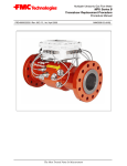
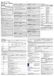
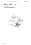
Service Manual
Syntron®
Electromagnetic Vibratory Feeder
Model: FH-22-C
1
Syntron® Electromagnetic Vibratory Feeder
Model: FH-22-C
Spring Replacement
Parts List
Magnet Replacement
Operating Specifications
FMC Technologies Inc. reserves the right to make changes at any time, without notice and without any
liability or other obligation on its part, in material, equipment, specifications and model. FMC Technologies
also reserves the right to discontinue the manufacture and sale of models, and the parts and components
thereof. For further detailed Information, contact FMC Corporation, Material Handling Equipment
Operation.
Safety Instructions: Product safety labels must remain highly visible on the equipment. Establish a
regular schedule to check visibility. Should safety labels require replacement contact
FMC Technologies, Inc. Material Handling Solutions for an additional supply free of charge.
SPRING REPLACEMENT GUIDE
WARNING: Before performing any maintenance work the electrical supply must be disconnected at
the safety disconncet switch.
CAUTION: If the trough must be removed to gain access to the spring clamping bolts, first provide a
means of supporting the trough and drive unit. The trough can be removed by removing the
mounting bolts located on the side of the wing plates.
1. Remove side covers (U), remove magnet cover (T). If the springs are replaced without separating the
drive unit from the trough, slit the diaphram (F) to gain access to install hardwood wedges.
2. Hold armature bracket in alignment with the base casting by driving hardwood wedges between the
armature bracket (E) and the base casting (R). This will insure correct alignment of the replacement
springs on the spring alignment bar (N).
3. Loosen the spring clamping bolts (J) enough to
permit removal of the clamping blocks (K). If
necessary, use penetrating oil.
4. With the clamp blocks removed the leaf springs
(M & Q) can be removed and examined.
5. When installing springs, the spring with spacers
on BOTH SIDES must be placed in the spring
cavity last, the other springs will have a spacer
on ONLY ONE SIDE. Insert these springs so
the spacer side will contact the plain side of the
previously placed spring. If spring spacers (P) are used, replace them in their original position, then
install the remaining springs, replacing the spring with spacers on both sides last.
6. With all springs installed and resting on the alignment bars (N) check alignment of armature bracket
(E). The armature bracket should not be twisted within the base casting. The core and armature ”pole
faces” should be parallel to each other.
2
7. Replace the center clamp block (K) and torque center spring clamping bolt (J). Refer To torque
specifications on page 7.
8. Replace the end clamp blocks (K) and tighten the end clamp bolts enough to hold the spring stack in
position.
9. Torque end spring clamping bolts (J) alternately to equalize the pressure across the springs
(780 ft. lbs.).
10. Remove wooden wedges and replace trough, if removed.
11. Adjust the air gap to .080 - .085”. See the ”Air Gap” section of Service Manual SM0570 or SM0572 for
procedure. Replace covers (T & U).
12. Connect the power supply. After the unit has bee operating for several hours, check clamping bolts for
tightness.
CAUTION: Never oil the spring assembly!
3
MAGNET REPLACEMENT
WARNING: Before performing any maintenance work, the electrical power supply must be disconnected at
the safety disconnect switch.
1. Remove back cover (T).
2. Loosen hex nut on set screw (A) and remove set screws.
3. Disconnect cable assembly from the power supply, loosen cable grip entering base casting (R) and pull
cable through cable grip into the base casting.
4. Remove the four (4) core clamping bolts from magnet assembly (B).
5. While carefully removing the magnet assembly, check for the presence of shims between the magnet
and base casting. Any shims must be replaced in original locations to ensure pole face alignment. If
magnet is replaced, it may be necessary to shim for proper pole alignment.
CAUTION: The magnet assembly weighs approximately 35 pounds
6. Observe the location of washers used connect the ground wire.
7. Connect the green ground lead to replacement magnet at its original location. Be sure to locate the
shakeproof lockwasher between the terminal and the core.
8. Replace magnet into the base casting using all original shims at the same locations. Replace magnet
mounting bolts.
9. Close air gap so that pole faces of magnet and armature are in contact. Snug down the clamping bolts
to hold the core in place to offer somr resistance when turning in the set screws to adjust the air gap.
Check from both top and bottom that core and armature faces are parallel. Eliminate any gap by using
shims betwwen magnet and mounting lugs on the base casting.
10. Insert cable through cable grip and reconnect cable leads to the power supply. Ensure ground
connection betwwen core and base casting is securely connected.
11. Adjust air gap to .080 - .085”. See ”The Air Gap” section of Service Manual No. SM0570 or
SM0572 for procedure.
12. Torque the magnet bolts, refer to page 7.
13. Replace the cover (T).
14. Check trough stroke – maximum allowable is .050”.
4
5
PARTS LIST – VIBRATORY FEEDER MODEL: FH-22-C
ITEM
A
B
C
D
E
F
G
H
J
K
M
N
P
Q
R
S
T
U
DESCRIPTION
Set Screw, Sq. Hd. , Cup Pt. (3/8”-16 x 1 1/2”)
Hex Nut (3/8”-16)
Magnet Assembly (230 V)
Magnet Assembly (460 V)
Magnet Assembly (575 V)
Cap Screw, Hex Hd. Gr. 5 (5/8”-18 x 1 3/4”)
H.S. Clipped Washer (5/8”)
Core Alignment Shims
Ground Jumper
Mach. Screw, Rd. Hd., Br. (1/4”-20 x 1 1/2”)
Lockwasher, Ext. Tooth (1/4”)
Armature Assembly
Cap Screw, Soc. Hd. (3/8”-16 x 1 1/4”)
Armature Bracket Casting
Diaphram
Diaphram Clamp (Base Casting)
Cap Screw, Hex Hd. (1/4”-20 x 3/4”)
Lockwasher (1/4”)
Diaphram Clamp (Armature Bracket)
Cap Screw, Hex Hd. (1/4”-20 x 3/4”)
Lockwasher (1/4”)
Spring Clamping Screw
Spring Clamp Block
End Leaf spring
Spring Aligning Bar
Cap Screw, Hex Hd. (5/16”-18 x 5/8”)
Lockwasher, Ext. Tooth (5/16”)
Spring Spacer Assembly
Leaf Spring Assembly
Base Casting
Base Casting
Cable Grip
Bracket
Cap Screw, Hex Hd. (3/8”-16 x 1”)
Name Plate
Drive Screw, P.K. Ty U (#2 x 3/16”)
Magnet Cover Assembly
Cap Screw, Hex Hd. (5/16”-18 x 1”)
Lockwasher (5/16”)
Cap Screw, Hex Hd. (3/8”-16 x 3”)
Hex Nut (3/8”-16)
Lockwasher (3/8”)
Side Cover
Gasket
Cap Screw, Hex Hd. (5/16”-18 x 1”)
Lockwasher (5/16”)
QTY
2
2
1
Only
4
4
2
1
2
2
1
4
1
1
1
14
14
1
10
10
3
3
2
2
4
4
1
25
1
1
1
1
2
1
4
1
3
3
2
2
2
2
2
8
8
PART NO.
H0403200
H0103001
D-212245-C
D-212245-E
D-212245-F
H0318701
A-800097-2
A-34981-A
B-192419-H
H0204902
H0114904
A-118669
H0421900
C-57803-A
A-59132G
B-28754
H0301201
H0112801
B-59130
H0301201
H0112801
A-59131
A-129010-C
A-129026
A-129014
H0306601
H0113004
A-129015
A-129025
D-190286-3
D-190286-5
0102X008
A-74118
H0310201
A-97298
H0430500
B-126476
H0307201
H0113001
H0311401
H0103001
H0113201
A-75119
B-204543-1
H0307201
H0113001
6
Used on Dust-Tight Units Only
Do not remove or paint over safety labels. Should safety labels require replacement, contact
FMC Technologies, Inc. Material Handling Solutions, Tupelo, MS 38802 1-800-356-4898 for an
additional supply free of charge.
When ordering parts, please furnish all the information on the nameplate.
OPERATING SPECIFICATIONS
Maximum trough weight:
Trough stroke range:
(Max. Trough Weight)
Minimum Natural Frequency:
*Maximum Current Rating: (nameplate)
Nominal Static Air Gap
140 Lbs.
.050”
4050 VPM (60 Cy)
10 Amps (230V/60 Cy)
5 Amps (460V/60 Cy)
4 Amps (575V/60 Cy)
.060”
TORQUE SPECIFICATIONS
ITEM
TORQUE VALUE DRY
TORQUE VALUE LUBRICATED
B
D
J
180 Ft-Lbs
30 Ft-Lbs
------
130 Ft-Lbs
23 Ft-Lbs
780 Ft-Lbs
•
When reading the current of the unit by using a tong meter, the meter reading must always be
multiplied by a value of 1.7. A tong meter does not reveal the same current as stamped on the
equipment nameplate due to the waveform characteristics of the feeder, when operating. Therefore, the
1.7 multiplier must be used.All current readings must be taken at the controller.
SM0549-082813
7
Corporate
FMC Technologies, Inc.
5875 N. Sam Houston Pkwy. W.
Houston, Texas 77086
P: +1 281.591.4000
Regional
FMC Technologies, Inc.
P.O. Box 1370
Tupelo, Mississippi 38802
P: 662.869.5711
F: 662.869.7493
Toll Free: 800.356.4898
[email protected]
FMC Technologies, Inc.
1525 S. 4710 W. Unit: E
Salt Lake City, Utah 84104
P: 801.296.9500
F: 801.296.9601
[email protected]
FMC Technologies Chile Ltda.
Callao 2970, Office 704
Las Condes, Santiago, Chile
P: +56 2.234.4418
+56 2.246.4361
F: +56 2.232.0825
[email protected]
FMC Technologies, Inc.
#2 Road No. 1
Changshu Export Processing Zone
Changshu, Jiangsu, China 215513
P: +82 0512.52299002
F: +86 0512.52297228
[email protected]
FMC Technologies Singapore Pte Ltd
13 Benoi Sector
Singapore 629860
P: +65 66683600
F: +65 63693385
[email protected]
Form No. SM0549 Revised 08.23.13
www.fmctechnologies.com
© 2013 FMC Technologies. All rights reserved.