1
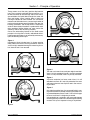
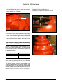
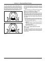
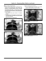
Smith Meter® Rotary Vane
Positive Displacement Meter
Installation/Operation/Maintenance
Issue/Rev. 0.9 (7/11)
Bulletin MN01011
Models:
Singles-Case Meters
SC-13, 13DI
SD-30, 30DI
SD3-S1
ST-40, 75, 160
SE & VE-42
SF & VF-60
Double-Case Meters
C2-S1 Through S7
E3 & E4-S1 Through S7, A1, A3
F4-S1 Through S7, A1, A3, V1
G6-S1 Through S7, A1, A3, V1
H8-S1 Through S7
JA & JB10-S1 Through S7
K12-S1 Through S7
M16-S1 Through S7
Non-Ferrous Aircraft
Fueling Meters
SD or ASD-3-NF
SD or ASD-3V-NF
SD or ASD-4-NF
SD or ASD-4V-NF
SF or ASF-4-NF
SF or ASF-4V-NF
SF or ASF-6-NF
SF or ASF-6V-NF
SG or ASG-6-NF
SG or ASG-6V-NF
Caution
Read instructions carefully before attempting to operate. Each meter is thoroughly tested before leaving the
factory. FMC Technologies Measurement Solutions, Inc. cannot accept claims for damage caused by air, line
contamination, or pressure shock waves during start-up.
Contents
Section 1 – Principle of Operation ................................................................................................................Page 2
Section 2 – Installation ..................................................................................................................................Page 3
Section 3 – Operation ....................................................................................................................................Page 4
Start-Up.............................................................................................................................................................Page 4
General Operating Information..........................................................................................................................Page 4
Section 4 – Maintenance . ..............................................................................................................................Page 5
Section 5 – Reversing Meter Rotation ..........................................................................................................Page 6
The Most Trusted Name in Measurement
Section 1 – Principle of Operation
These meters are of the rotary positive displacement
type. The accurately-machined housing contains a rotor which revolves on ball bearings and carries evenlyspaced blades. As liquid flows through the meter, the
rotor and blades (vanes) revolve about a fixed cam
causing the blades to move outward. The successive
movement of the blades forms a measuring chamber of
precise volume between two of the blades, the rotor, the
housing, the bottom, and the top covers. A continuous
series of these closed chambers is produced for each
rotor revolution. Neither blades nor rotor contact the
stationary walls of the measuring chamber.
One of the outstanding features of the Smith meter
principle is that the flow is literally undisturbed while it
is being metered. Energy is not wasted by unnecessary
hydraulic bending of the liquid.
Figure 3
Figure 1
Unmeasured liquid (shaded area) is shown entering
meter. Rotor and vanes are turning clockwise. Vanes A
and D are fully extended forming the measuring chamber; Vanes B and C are retracted.
Figure 4
Figure 1
Figure 2
The rotor and vanes have made one-eighth revolution.
Vane A is fully extended; Vane B is partially extended;
Vane C is fully retracted; Vane D is partially retracted.
Figure 3
A quarter revolution has been made. Vane A is still
extended and Vane B is now fully extended. An exact
and known volume of new liquid is now in the measuring chamber.
Figure 4
One eighth revolution later, the measured liquid is moving out of the meter. A second measuring chamber is being created between Vanes B and C. Vane A has begun
to retract and Vane C is beginning to extend.
In three-eighths of a revolution, one measured segment
of fluid has been passed and a second segment is being
created. This cycle is repeated as long as liquid flows.
Figure 2
Page 2 • MN01011
Issue/Rev. 0.9 (7/11)
Section 2 – Installation
1. The meter and its accessories are precision instruments and should be treated accordingly. Prior to
installation, the equipment should be protected from
adverse weather conditions and accidental abuse.
2. The installation should provide protection from sand,
dust, rain, sleet, etc. where extreme adverse weather
conditions are encountered.
3. The meter should be mounted on a suitable base or
platform so it will not be supported by the piping.
Meters are generally designed to be installed in a
horizontal line with the mounting feet supported
in a plane parallel with the ground or floor. Meters with the letter "V" in the model number, are
designed to be installed in a vertical line with
mounting feet supported in a plane parallel with
the ground or floor. Orientation other than that
for which the meter is designed is not recommended.
Dimensional outline drawings showing size and location of anchor holes are available for all meters.
4. Install the meter so that it cannot be accidentally
drained of product; however, it is advisable to drain
the meter of water and sediment periodically.
When installing the meter, be sure the drain plug is
accessible.
5. Piping must not produce an undue strain on the meter.
6. Protect the meter and system against the effects of
thermal expansion with a relief valve.
WARNING!
Thermal Pressure
Thermal expansion of liquid in this equipment can
cause high pressure damage. A Thermal Pressure
Relief Valve may be necessary in the system.
Issue/Rev. 0.9 (7/11)
7. Where necessary, a deaerator or air eliminator should
be installed to keep air and vapor out of the meter.
8. All piping should be internally cleaned before the
meter is put into operation.
Rust, dirt, welding shot, and other foreign material
should be removed completely.
Remove the inner mechanism in double-case meters or the rotor and blade assembly in single-case
meters and flush the lines to prevent damage to the
metering element.
The meter should be protected by at least a 4-mesh
strainer.
All non-ferrous meters must be downstream of at
least a 5-micron filter.
9.Where necessary, a flow-limiting valve should be
installed downstream of the meter to protect it from
excessive flow rates.
10.Remove the inner mechanism if the system is to be
pressure-tested with water or if debris is to be flushed
from the system.
11.Do not calibrate with water or allow water to stand
in the meter.
Flush the meter with a light lubricating oil if it is left
idle or stored.
12.Unless otherwise specified, meters normally flow
from left to right when viewed from the flanged side
of the housing.
Most meters can be changed to flow from right to
left. Consult factory.
13.A counter may be located in any one of four 90°
positions. Large numeral counters may be located
in any of eight 45° positions.
MN01011 • Page 3
Section 3 – Operation
Start-Up Procedure
Use precaution when starting-up a PD meter in a new
line that is not purged of air and packed with fluid. Never
start a meter by haphazardly opening flow control valves.
Due to the nature of their design and the close running
clearances between moving parts, all PD meters risk
being damaged if started in this manner. Primarily, a
pressure differential can form across the rotor walls
due to air on the inside and line pressure outside the
rotor. This condition causes the rotor slots to collapse
and pinch the blades, which in turn causes the paddle
to crack and separate at the yoke. Secondly, air being
purged by upstream product can spin the measuring
element to excessive speeds and should liquid suddenly
hit the measuring element while it is spinning a hydraulic
brake takes effect causing a line shock which could result in a fractured rotor, a broken blade or a combination
of both. Therefore, air and gas must be removed from
the meter internals prior to normal operation. Complete
venting can be accomplished by performing the following
start-up procedures.
1. When starting double case PD meters, first remove
the pipe plug located in the outer housing cover and
use the pipe tap to install an air bleed system that
can be regulated by a control valve.
Note that, in the event of starting single case meters,
an air vent option is not available. Therefore, air
trapped inside a single case meter must be gradually purged downstream as the flow rate is slowly
increased.
2. With the downstream valve completely closed and
only gravity pressure being exerted, slowly open
the upstream valve until liquid begins to flow into
the meter. Open the bleed valve and vent until no air
or gas is apparent. The meter housing vents much
faster than the rotor.
3. Close the upstream valve prior to starting pumps
and repeat step 2. Venting can take several minutes
if the pressure is low and the liquid viscosity is high.
4. Slowly open the downstream valve until flow
begins. Notice that more air or gas will be vented.
Continue to operate at this very low rate until venting
is complete.
5. Close the bleed valve and fully open the downstream valve. The upstream valve can now be slowly
opened to establish full flow.
This procedure must be followed each time the
meter is drained.
General Operating Information
1.Inlet and outlet valves should be operated slowly to
avoid line shock. Abrupt closure can create forces
in excess of normal line pressure. This could result
in damage to the meter and other equipment.
Page 4 • MN01011
2.Do not manually operate a reset-type counter when
the meter is operating.
3.The securing pin in a ticket printer head must be
in the down or locked position when the meter is
operating.
4.Meters equipped with manual calibrators or ATC’s
can only operate in one direction.
5.Calibration adjustment has been made at the factory
for zero error at maximum nameplate capacity on
2 cP solvent. Due to variations in operating conditions (e.g., actual liquid, pressure, and flow rate), the
meter should be proved after installation. See API
referenced standards.
6.Manual meter calibration is accomplished by adjusting the calibrator dial. Calibration may be changed in
increments of .0005 (1/20th of 1 percent). The dial
is marked ± and is concealed under a wire-sealed
cover on the calibrator adjuster located on the top
dome of the meter. The amount of product indicated
by the meter increases when the calibrating dial is
turned in a counter-clockwise direction and diminishes if the dial is turned in a clockwise direction. On
meters with ATC (Automatic Temperature Compensation), each notch provides a change equal to the
Coefficient of Expansion per degree F. For example,
an ATC Calibrator for 38° API would provide .00048
per notch as 38° API has a Coefficient of Expansion
of .00048/°F. If an ATG (Automatic Temperature Gravity Compensator) is installed in the meter stack-up,
calibration adjustment is made using the screw adjustment located under the small wire-sealed cover
labeled “meter adjustment.” A clockwise direction
decreases registration.
7.To obtain maximum service from Smith meters, it is
suggested that detailed records be maintained.
Data such as model, serial number, operating rate,
type of product, meter clearances, totalizer readings,
meter factor, and other pertinent information should
be recorded. Such information is an excellent guide in
scheduling a preventive maintenance program.
Reference Publications
American Petroleum Institute
2101 L Street, Northwest
Washington, DC 20037
Manual of Petroleum Measurement Standards.
API Chapter 4 – Proving Systems.
API Chapter 5, Section 5.2 – Measurement of Liquid
Hydrocarbons by Displacement Meter Systems.
API Chapter 12, Section 2 Field Manual – Instructions
for Calculating Liquid Petroleum Quantities Measured
by Turbine or Displacement Meters.
Issue/Rev. 0.9 (7/11)
Section 4 – Maintenance
1. If your meter has a calibrator, it requires lubrication
with light oil (SAE-10). Initially, apply it after approximately five hours of operation and then about twice
yearly. (See oil cup – Figure 5).
Reference Literature:
• P0605.XX Packing Gland Parts List
• P1202.XX Lubricants and Sealants Parts List
• P1205.XX Tools Parts List
Figure 5 – Oil Cup (E3)
2. PD meters may be used in petroleum applications
where the corrosion/erosion is normally minimal. PD
meter pressure containing housings are designed
with an adequate allowance for petroleum applications. Consult the factory for other applications or for
actual material allowances.
Figure 6 – Lubrication Fitting (M16)
High Pressure Packing Gland Maintenance
(Models C2 Through M16 – S1, S3, S5, S6, and S7 )
Silicone Oil (or Glycerine) is used as a sealant and lubricant in this type of packing gland. The gland should
be serviced on an interval determined by experience,
however, the period between injections is recommended
to not exceed 60 days.
Ambient Temperature
Lubricant
-4°F to 300°F (-20°C to 150°C)
High Purity (99%) Glycerine
-40°F to 400°F (-40°C to
204°C)
Dow Corning DC200 (or equal)
Silicone Oil
Figure 7 – Lubrication Fitting (F4)
If the meter has been idle for a period of time, prior to
startup, inject the packing gland with 1 oz. of Silicone
oil (or Glycerine).
The lubricant injection volume is recommended to be
1 fluid oz. injected through the lubricant (Zerck) fitting
(Figure 6 and Figure 7). The packing gland design and
reservoir overflow into the meter ensures that the packing gland cannot be overfilled.
Note: Lubricant grease should never be used in the packing gland.
Issue/Rev. 0.9 (7/11)
MN01011 • Page 5
Section 5 – Reversing Meter Rotation
The clutch-type calibrator and most Smith Meter accessories must be driven in a counter-clockwise rotation as
viewed from the top. Since the meter rotor will revolve in
either direction, flow may be reversed and a clockwise
(CW), right-hand meter may be changed to a counterclockwise (CCW), left-hand meter and vice versa.
Figure 8
Unless otherwise specified, standard meters flow from
left to right, CW rotation (see Figure 8). To change flow
from right to left, CCW rotation (see Figure 9), proceed
as follows:
• Remove counter(s) and calibrator from top of meter.
Meters 3"-8"; Single-Case; S1, S2, V1, and A1
Double-Case; and Non-Ferrous Meters
Note: To reverse rotation, the jackshaft pinion gear must
have the same number of teeth as the lower gear of the
intermediate gear pinion. For a few special gear trains,
these gears are not the same ratio, and to reverse rotation, additional gears are required. Consult factory for
assistance.
1. Reverse rotation by removing and reversing the location of the jackshaft pinion gear and the intermediate
gear pinion as noted in Figure 11.
a. The calibrator drive gear remains in its original
position.
b. After switching gears, it will be noted that the jackshaft pinion no longer serves any purpose and may
be removed if desired.
c. Replace washers and cotter pins.
Meters 3"-8", A3, S3-S7 Double-Case and All
10"-16" Meters
The gear train is located on the inside of the outer
cover. Refer to respective service manual for specific
instructions on removing the cover and then follow steps
outlined above.
Figure 9
Issue/Rev. 0.9 (7/11)
MN01011 • Page 6
Section 5 – Reversing Meter Rotation (continued)
Meters 2" SC-13 and C2, S1-S7
1. Reverse, CCW, rotation requires a reversing kit consisting of an intermediate gear, stud, washer, and
cotter pin. To change rotation to CCW: 1. Remove
the jackshaft pinion gear; 2. install the new stud in
the hole provided on the cover; 3. install the jackshaft
pinion gear on the new stud and the intermediate gear
on the jackshaft.
a. The calibrator drive gear remains in its original
position.
b. For CW rotation, the procedure is reversed and the
intermediate gear no longer serves any purpose
and may be removed.
c. Replace washers and cotter pins.
2. Replace calibrator and counter(s).
a. Be sure calibrator gear and meter gear mesh
properly before tightening adapter screws.
Figure 12 – Meters 2" SC-13 and C2, S1-S7,
Clockwise Rotation
Figure 10 – Model E3-S1, Clockwise Rotation
Figure 13 – Meters 2" SC-13 and C2, S1-S7,
Counter-Clockwise Rotation
Figure 11 – Model E3-S1, Counter-Clockwise Rotation
Issue/Rev. 0.9 (7/11)
MN01011 • Page 7
Revisions included in MN01011 Issue/Rev. 0.9 (7/11):
Page 5: Inserted Figure 5, 6, and 7.
The specifications contained herein are subject to change without notice and any user of said specifications should verify from the manufacturer that the specifications are currently
in effect. Otherwise, the manufacturer assumes no responsibility for the use of specifications which may have been changed and are no longer in effect.
Contact information is subject to change. For the most current contact information, visit our website at www.fmctechnologies.com/measurementsolutions and click on the
“Contact Us” link in the left-hand column.
Headquarters:
500 North Sam Houston Parkway West, Suite 100, Houston, TX 77067 USA, Phone: +1 (281) 260 2190, Fax: +1 (281) 260 2191
Measurement Products and Equipment:
Erie, PA USA +1 (814) 898 5000
Ellerbek, Germany +49 (4101) 3040
Barcelona, Spain +34 (93) 201 0989
Beijing, China +86 (10) 6500 2251
Buenos Aires, Argentina +54 (11) 4312 4736
Burnham, England +44 (1628) 603205
Dubai, United Arab Emirates +971 (4) 883 0303
Los Angeles, CA USA +1 (310) 328 1236
Melbourne, Australia +61 (3) 9807 2818
Moscow, Russia +7 (495) 5648705
Singapore, +65 6861 3011
Integrated Measurement Systems:
Corpus Christi, TX USA +1 (361) 289 3400
Kongsberg, Norway +47 (32) 286700
Dubai, United Arab Emirates +971 (4) 883 0303
Visit our website at www.fmctechnologies.com/measurementsolutions
Printed in U.S.A. © 7/11 FMC Technologies Measurement Solutions Inc. All rights reserved. MN01011 Issue/Rev. 0.9 (7/11)