1
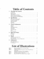
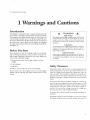
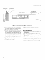
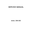
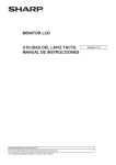
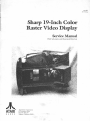
TM-304 1st Printing Sharp 19-Inch Color Raster Video Display Service Manual With Schematic and Illustrated Parts List JI\. ATARI® G A M E S Atari Games Corporation 675 Sycamore Drive P.O. Box 361110 Milpitas, California 95035 © 1987 by Atari Games Corporation All rights reserved. No part of this publication may be reproduced by any mechanical, photographic, or electronic process, or in the form of a phonographic recording, nor may it be stored in a retrieval system, transmitted, or otherwise copied for public or private use, without permission from the publisher. The game play, all graphic designs, this technical manual, its accompanying schematic diagrams, and the display manual are protected by the U.S. Copyright Act ofl976. This Act provides for increased penalties for violating federal copyright laws. Courts can impound infringing articles while legal action is pending. Ifinfringers are convicted, courts can order destruction of the infringing articles. In addition, the Act provides for payment of statutory damages of up to $250,000 in certain cases. Infringers may also have to pay costs and attorneys' fees and face an imprisonment of up to five years. Atari Games Corporation will aggressively enforce its copyrights against any infringers. UT will use all legal means to immediately halt any manufacture, distribution, or operation of a copy of video games made by us. Anyone who purchases such copies risks forfeiting such a game. Published by: Atari Games Corporation 675 Sycamore Drive P.O. Box 361110 Milpitas, California 95035 Printed in the U.S.A. SR Table of Contents I Warnings and Cautions Introduction . . . . . . . . . . . . . . . . . . . . . . . . . . . . . . . . . . . . . . . . . . . . . . . . . . . . . . . Before You Start . . . . . . . . . . . . . . . . . . . . . . . . . . . . . . . . . . . . . . . . . . . . . . . . . . . . Safety Measures . . . . . . . . . . . . . . . . . . . . . . . . . . . . . . . . . . . . . . . . . . . . . . . . . . . . Cathode-Ray Tube Handling . . . . . . . . . . . . . . . . . . . . . . . . . . . . . . . . . . . . . . . . . . Replace with Proper Components . . . . . . . . . . . . . . . . . . . . . . . . . . . . . . . . . . . . . . Final Testing Before Reinstalling Display . . . . . . . . . . . . . . . . . . . . . . . . . . . . . . . . . . 2 Specifications P0wer Input and Consumption . . . . . . . . . . . . . . . . . . . . . . . . . . . . . . . . . . . . . . . . Temperature and Humidity . .. .... .. . ..... . . .. . . . .... . ....... .. . .... ·.. Current and Voltages . . . . . . . . . . . . . . . . . . . . . . . . . . . . . . . . . . . . . . . . . . . . . . . . CRT Specifications . . . . . . . . . . . . . . . . . . . . . . . . . . . . . . . . . . . . . . . . . . . . . . . . . . Connectors . . . . . . . . . . . . . . . . . . . . . . . . . . . . . . . . . . . . . . . . . . . . . . . . . . . . . . . . Pattern Size . . . . . . . . . . . . . . . . . . . . . . . . . . . . . . . . . . . . . . . . . . . . . . . . . . . . . . . . 3 5 4 4 6 6 6 6 6 6 Signal Test Points RGB Signals . . . . . . . . . . . . . . . . . . . . . . . . . . . . . . . . . . . . . . . . . . . . . . . . . . . . . . . 6 Sync Signal . . . . . . . . . . . . . . . . . . . . . . . . . . . . . . . . . . . . . . . . . . . . . . . . . . . . . . . . 7 Repair Cathode-Ray Tube Replacement . . . . . . . . . . . . . . . . . . . . . . . . . . . . . . . . . . . . . . . . Yoke Replacement . . . . . . . . . . . . . . . . . . . . . . . . . . . . . . . . . . . . . . . . . . . . . . . . . . Horizontal-Output Transformer Replacement . . . . . . . . . . . . . . . . . . . . . . . . . . . . . 6 3 3 3 3 3 3 Control Adjustments Briglltness . . . . . . . . . . . . . . . . . . . . . . . . . . . . . . . . . . . . . . . . . . . . . . . . . . . . . . . . . Tracking.................................. . ................ . ...... Horizontal Centering . . . . . . . . . . . . . . . . . . . . . . . . . . . . . . . . . . . . . . . . . . . . . . . . Vertical Hold .................. .......... . ... .. . . ..-. . . . . . . . . . . . . . . . . . Vertical Size . . . . . . . . . . . . . . . . . . . . . . . . . . . . . . . . . . . . . . . . . . . . . . . . . . . . . . . Horizontal Width . . . . . . . . . . . . . . . . . . . . . . . . . . . . . . . . . . . . . . . . . . . . . . . . . . . Focus . . . . . . . . . . . . . . . . . . . . . . . . . . . . . . . . . . . . . . . . . . . . . . . . . . . . . . . . . . . . Horizontal Hold . . . . . . . . . . . . . . . . . . . . . . . . . . . . . . . . . . . . . . . . . . . . . . . . . . . 4 1 1 1 2 2 3 7 7 8 Adjustments Purity Adjustments . . . . . . . . . . . . . . . . . . . . . . . . . . . . . . . . . . . . . . . . . . . . . . . . . Convergence Adjustments . . . . . . . . . . . . . . . . . . . . . . . . . . . . . . . . . . . . . . . . . . . . B+ Adjustment . . . . . . . . . . . . . . . . . . . . . . . . . . . . . . . . . . . . . . . . . . . . . . . . . . . . 9 9 10 List of IDustrations Figure 1 Figure 2 Figure 3 Figure 4 Figure 5 Figure 6 Figure 7 Overview of Sharp 19-Inch Color Raster Display . . . . . . . . . . . . . . . . . . Display Pattern Sizes . . . . . . . . . . . . . . . . . . . . . . . . . . . . . . . . . . . . . . . Adjustable Controls and Test Points on Main Chassis PCB and Control PCB . . . . . . . . . . . . . . . . . . . . . . . . . . . . . . . . . . . . . . . . . . . . . Blanking Pulse Waveform of Video Amplifiers . . . . . . . . . . . . . . . . . . . . Adjustable Controls on Picture Tube Socket PCB . . . . . . . . . . . . . . . . . Purity and Convergence Adjustments . . . . . . . . . . . . . . . . . . . . . . . . . . . Sharp XM-2001N Video Display Schematic Diagram . . . . . . . . . . . . . . 2 4 5 5 5 10 18 19" Standard-Resolution Display I Warnings and Cautions Introduction This display is contained within a separate chassis inside the game cabinet. The Main Chassis printed-circuit board (PCB) is mounted to the display chassis under the video tube, the Control PCB is located next to the Main Chassis PCB, and the Picture Tube Socket PCB is attached to the neck pins of the video tube. Input signals for the display are supplied through a 6-pin harness connector to the Main Chassis PCB. (See Figure l.) WARNING High Voltage This display contains high voltages capable of delivering lethal quantities of energy. To avoid danger, do not attempt to service the chassis until you have observed all precautions necessary for working on high-voltage equipment. Before You Start X-Radiation This chassis has been designed for minimum X-radiation hazard. However, to avoid possible exposure to soft Xradiation, it is imperative that you never modify the high-voltage circuitry. Never attempt to work on a display until you are familiar with servicing precautions and procedures necessary for high-voltage equipment. Remember, any video display has three sources of possible danger: If you drop the display and the picture tube breaks, it will implode! _Shattered glass and the yoke can fly 6 feet or more from the implosion. Use care when replacing any display. Implosion Hazard • Strong electric shock, due to high voltage or AC line voltage • X-ray radiation • Implosion Safety Measures Therefore, never modify any circuit in this display. Good safety habits will allow you to automatically take the proper precautions, even if you are rushed. Whenever you work on a display, always ground the chassis first. Also, use only one hand. This avoids the possibility of carelessly putting one hand on the chassis or ground and the other on an electrical connection. Doing so could cause a severe electrical shock. Do not service this video display until you are thoroughly familiar with all warnings and safety measures given in this chapter. Ifyou service the Sharp Color Raster Display on a test bench, use only the power supply that came with the game or a 100 VAC isolation transformer. (Refer to the parts list in the game manual for the Atari part number of the power supply assembly.) Do not use line voltage because the voltage produced by this source will damage this display. To prevent fire or shock hazard, never expose this display to moisture. Periodically check for frayed insulation on the wires within the display. If frayed wires are found, replace them with the 1 19" Standard-Resolution Display Figure 1 Overview of Sharp 19-Inch Color Raster Display same gauge and length of wire. Always observe the original lead dress (routing and length of harness wires). Use extra precaution in the high-voltage circuitry areas of the display. Ifa short circuit occurs, replace any components that indicate they may have overheated. other mounting parts. See Chapter 5, step 3 of the CathodeRay Tube Replacement procedure to discharge the high voltage. Replace with Proper CompoCathode-Ray Tube Handling nents Wear safety goggles and heavy gloves for protection whenever you handle a cathode-ray tube (CRT). Keep other people away if they are not wearing safety goggles. Never lift the CRT by the neck; the neck should only be used to guide the lifting process. Use extreme care when handling the CRT. Rough handling may cause the CRT tube to implode. Do not nick or scratch the glass or subject any undue pressure upon the tube at any time. If servicing the CRT, first discharge the high voltage on the anode connection to chassis ground-not to the cabinet or Maintain the specified values of all components within the display. Failure to do so could cause a rise in the high voltage. 2 The cathode-ray tube of this display employs integral implosion protection. For continued safety, replace it only with a tube of the same type number. Refer to the parts lists in Chapter 7 of this manual. For continued product safety, use only exact replacement parts, especially for those parts identified in the parts lists with the A symbol and on the schematics with shading. 19" Standard-Resolution Display Final Testing Before Reinstalling Display 1. Inspect all harness wiring within the display area. Be sure no wires or cables are pinched between the cabinet and other parts in the display. Before reinstalling this color display into the game, you must check the following: 2. Replace all protective devices such as insulating fish paper, compartment covers, and shields. 2 Specifications Power Input and Consumption Line Voltage 100 VAC, within+ 10% and -15% Line Frequency 47 to 63 Hz 74 Wmaximum Power Consumption Temperature and Humidity Ambient Air Temperature: 0°C to +55°C ( +32°F to Operating +130°F) Non-operating -40°C to +65°C (-40°F to +149°F) 10% to 90%, non-condensing Humidity Current and Voltages CRT Anode Current (Average) Less than 650 µA High Voltage 24 kV ±1.5 kV CRT Specifications Convergence Tolerance: 0.010 inch (0.25 mm) maximum At Screen Center rmsconvergence 0.020 inch (0.5 mm) maximum At Screen Edges rmsconvergence Color Purity Practically uniform throughout the screen area after degaussing with a hand-held degaussing coil. Scan Rates: Horizontal 15.75 kHz, within ±500 Hz Vertical 60 Hz, within ± 5 Hz CRT Type Vl3510YWB22, 19-inch, 90° Tilt of Deflection Yoke Declination of a horizontal line is within 0.10 inch (2.54 mm). Connectors 6-Pin Connector for Video Signals: Pin 1 Green Pin 2 Red Pin 3 Blue Pin 4 Ground Pin 5 Ground Pin 6 Negative Composite Sync 3-Pin Connector for Power: Pin 1 100 VAC Pin 2 No Connection Pin 3 Neutral Pattern Size You should be able to reproduce the patterns as shown in Figure 2. 3 19" Standard-Resolution Display Maximum size Minimum size CRT Figure 2 Display Pattern Sizes 3 Control Adjustments WARNING NOTE Remember to observe the precautions regarding high voltages when making adjustments to this display! Too high a brightness level will cause the retrace lines to show; too low a level will cause the entire screen to be dark and obscure. NOTE Before making any of the following adjustments, turn on the display and allow it to warm up for at least 5 minutes. Brightness The BRIGHT control R495 should be adjusted if the picture image is either too bright or too dark. See Figure 3 for the location of the Brightness control on the Control PrintedCircuit Board (PCB). 1. Place the game in the attract or play mode. 2. Using the Brightness control, adjust the display for a pleasing level of brightness. 4 3. If the proper level of brightness cannot be obtained by adjusting the Brightness control, adjust the SUBBRIGHT control R492 as follows: a. Set the game to display the self-test diagnostic pattern showing a white crosshatch. (Refer to the Self-Test chapter in the game manual for details on selecting this pattern.) b. Attach an oscilloscope probe to each collector of the video amplifiers Q801, Q802, and Q803 and observe the blanking pulse waveform of each amplifier. The one with the most deflection of the blanking pulse is the lead gun. c. Adjust the Sub-Brightness control so that the wave- form is similar to the one shown in Figure 4. Tracking The Screen, Brightness, the three Bias, and two Drive controls should be adjusted if the picture image is not the correct 19" Standard-Resolution Display SIGNALD INPUT Main P W. B R451 R-GAIN p A461 G-GAIN p VIDEO SIGNAL POLARITY SW H . ORIVE • [iJ 2.5A \ G D ·-=--~ 3A I S~RE HOAIZONT OUTPUT FUSE p 0601 A533 ~JPSOUNOO:::~T 0IC~ p @ SOUND INPUT I 0501 LJ [iJ ···o ~o PWB A492 SUB-BRIGHT t - - - - - - - - - - 1 V-UN I 601 CONTROL R•71 B~ 0 CD H -StZE L 602 I 701 ~ POWER CHOKE R 707 • + 8 ADJ =m= ;z5v 3A 'USE ~ T60t 'BT -=-''02 .,701 125 V 2 5A 'USE R495 BRIGHT R515 v- HOLD H-HOLD SW.702 DEGAUSSING - SW Figure 3 Adjustable Controls and Test Points on Main Chassis PCB and Control PCB BLANKING PULSES 1so voe ri I ~ I I I ,-- ri -~ I Figure 4 Blanking Pul~ Waveform of Video Amplifiers color or brightness, and whenever the purity and convergence is adjusted. (See Figure 3 for the location of the Screen and Brightness controls and Figure 5 for the Bias and Drive controls.) R809 8-0RIVE -1 I '-J ri ILI I I r'-J Figure 5 Adjustable Controls on Picture : Tube Socket PCB 5 19" Standard-Resolution Display l. Remove power from both the game and the display. 2. Unplug the 6-pin video-signal connector, which 1s wired to the Main Chassis PCB. 3. Set the R-DRIVE control R807 and the B-DRIVE control R809 to their mechanical centers. 4. Set all three BIAS controls R813, R814, and R815 to their mechanical centers. 5. Set the Brightness control to its mechanical center and the Screen control fully counterclockwise. 6. Ifthe game has a self-test diagnostic pattern for the color purity test, set the game to display this test to complete the white tracking procedure. Ifthe game does not have a color purity test, an RGB signal generator capable of producing a gray and a white raster is necessary. 7. Reconnect the 6-pin video-signal connector and apply power to the display. 8. Set the game to display the self-test diagnostic pattern showing the gray raster. 9. Slowly adjust the Screen control until the CRT screen displays the first hint of color. Do not adjust the Bias control for the color that first appeared on the screen. Instead, slowly adjust the Bias controls for the other two colors until the screen displays a faint gray color. 10. Set the game to display the self-test diagnostic pattern showing the white raster, and adjust the R-Drive and BDrive controls for a uniform white. (Note: repeat steps 8 and 9 so that both the gray and white rasters have uniform color.) 11. Return the game to the attract mode. Ifnecessary, adjust the Brightness control if the screen appears to be too dark or too bright. Horizontal Centering The Horizontal Centering control should be adjusted if the picture is not centered on the screen, as indicated by a black area at either the left or the right edge. Figure 3 shows the location of the H-CENT control R628 on the Control PCB. Adjust this control until a normal screen image is obtained. Vertical Hold The Vertical Hold control should be adjusted if the picture drifts straight up or down on the screen. Figure 3 shows the location of V-HOLD control RSlS on the Control PCB. Tum this control until the picture no longer drifts up or down on the screen. Vertical Size The Vertical Size control should be adjusted if the screen image is either not filling the screen vertically, or if it is overscanning the screen vertically. Figure 3 shows the location ofV-SIZE control RS23 on the Control PCB. l. Set the game for the diagnostic test that displays the convergence grid and dots. 2. Adjust V-SIZE control until the top and bottom grid lines are along the top and bottom edges of the screen. These grid lines should not disappear off the edges of the screen, which would indicate overscanning. Horizontal Width The Horizontal Width coil should be adjusted if the screen image is either too wide or narrow. Figure 3 shows the location ofHORIZ WIDTH coil L601 on the Main Chassis PCB. 1. Set the game for the diagnostic test that displays the convergence grid and dots. 2. Use only a non-metallic Allen wrench (commonly called a "tweaking tool") to adjust the Horizontal Width coil until the right and left grid lines run along the edges of the screen. These grid lines should not disappear off the edges of the screen, which would indicate overscanning. Focus The Focus control should be adjusted if the screen image is not sharply defined. The Focus control is attached to the top of the horizontal-output transformer as shown in Figure 3. Tum this control until you get optimum screen sharpness. Horizontal Hold The Horizontal Hold control should be adjusted if the picture is drifting sideways across the screen. Figure 3 shows the location of H-HOLD control R616 on the Control PCB. Adjust this control until the black lines no longer slant downward or upward and you get a normal screen image. 4 Signal Test Points RGBSignals The red, green, and blue signals can be checked at the collectors of Q801 (Red), Q802 (Green), and Q803 (Blue). 6 These transistors are located on the Picture Tube Socket PCB. 19" Standard-Resolution Display Sync Signal · The negative composite synchronization (Sync) signal can be checked at pin 6 of the 6-pin video-signal connector, which is located off of the Main Chassis PCB. Do not jam a test probe into the connector pin, because this may cause the pin to stretch and fall out of the connector housing. 5Repair WARNING Before removing or installing any component of this display, always disconnect the power source! Observe the precautions regarding high voltages and cathode-ray tube handling when servicing this display. 9. CAREFULLY remove the CRT by easing it out the front of the chassis. 10. Place the CRT on a soft mat in a protected location. 11. Install a CRT in the reverse order of removal. Then adjust the SCREEN control G2 as follows: a. Apply power to the display. b. Tum the Brightness control on the Control PCB to the fully counterclockwise position. NOTE The tools required to replace these assemblies include: 5/16-inch hex socket wrench, Phillips screwdriver, and a soldering iron. c. Adjust the Screen control for a dimly-lighted screen. This control is attached to the horizontal-output transformer as shown in Figure 3. d. Readjust the Brightness control as described in Chapter 3. Cathode-Ray Tube Replacement 1. Disconnect the 6-pin video-signal connector located off the Main Chassis PCB. 2. Remove the display assembly from the cabinet as described in the game manual. Yoke Replacement NOTE You must reconverge the picture whenever the yoke is replaced. 3. Discharge the high voltage from the cathode-ray tube (CRT) as follows: a. Attach one end of a well-insulated, 20 kV-resistive jumper to ground. 1. Disconnect the 6-pin video-signal connector located off the Main Chassis PCB. b. Briefly touch the free end of the resistive jumper to the anode by sliding it under the anode cap. 2. Remove the display assembly from the cabinet as described in the game manual. c. Wait two minutes. d. Discharge the anode again. 3. Discharge the high voltage from the CRT as described in step 3 of Cathode-Ray Tube &placement. e. CAREFULLY remove the large high-voltage anode connector from the cathode-ray tube. 4. Unplug the Picture Tube Socket PCB from the rear of the CRT. 4. Unplug the Picture Tube Socket PCB from the rear of the tube. 5. Use a thin knife or a single-edged razor blade and carefully loosen the three rubber wedges from the CRT surface. 5. Unplug the degaussing coil 2-pin connector from the Main Chassis PCB. 6. Unplug the 4-wire connector attaching the yoke wires to the Main Chassis PCB. 7. Unhook the spring that holds the braided ground wire (located near the bottom comer of the CRT). 8. Use a 5/16-inch hex socket wrench to remove the four screws holding the CRT to the steel frame. 6. Loosen the Phillips-head screws used to tighten the two neck clamps around the neck of the CRT. 7. Slide the magnet assembly and the yoke assembly off the end of the CRT. 8. Replace the yoke assembly in the reverse order of removal. 7 19" Standard-Resolution Display Horizontal-Output Transformer Replacement 1. Disconnect the 6-pin video-signal connector located off the Main Chassis PCB. 2. Remove the display assembly from the cabinet as described in the game manual. 3. Discharge the high voltage from the CRT as described in step 3 of Cathode-Ray Tube Replacement. 4. Open the anode holder and remove the anode lead. 5. Unplug the Picture Tube Socket PCB at the rear of the CRT. Then unsolder the red wire (goes to K806) and white wire (goes into the socket) on that PCB. 8 6. Remove the Phillips-head screws that secure the metal cover over the transformer. 7. Remove the Phillips-head screw holding the metal bracket to the right side of the transformer. . 8. Unsolder the 11 transformer connections on the bottom side of the Main Chassis PCB. 9. Lift the transformer off the Main Chassis PCB. 10. Replace the transformer in the reverse order of removal. Be sure t? check the picture for sharpness. If appropriate, readjust the Focus control as described in Chapter 3. 19" Standard-Resolution Display 6 Adjustt11ents WARNING Remember to observe the precautions regarding high voltages when making adjustments on this display! Before adjusting the display, remove the display assembly from the cabinet as described in the game manual. Leave all cables connected between the display assembly and other parts of the game. a. Tum off the red and blue guns of the CRT by rotating the R-Bias and G-Bias controls to the fully counterclockwise position. b. Readjust the purity magnets, if necessary, for a uniformly blue screen. This may interact with the previous adjustments. 5. Return the R-Bias, G-Bias, and B-Bias controls to their original settings. Check the screen for a pure white display that is not tinted with other hues. 6. Reinstall the display in the game. 7. Perform the convergence adjustments. Purity Adjustments 1. Set up the display for the purity adjustments as follows: a. If you will also be adjusting the convergence of the outer screen area, loosen the mounting screws for both the deflection yoke and the magnet. b. Position the cabinet so that the CRT faces either north or south. c. Degauss the CRT tube with a hand.:.held degaussing coil. 2. Adjust for red purity as follows: a. Tum off the green and blue guns of the CRT by rotating the G-BIAS R814 and B-BIAS R815 controls to the fully counterclockwise position. (See Figure 5 for the location of the Bias adjustments.) b. Set the game to display any self-test diagnostic pattern that shows solid white. Keep this image throughout the purity adjustments. (Refer to the Self-Test chapter in the game manual for details on selecting this pattern.) c. Rotate and spread the tabs of the purity magnets until the screen image is centered both horizontally and vertically. (See Figure 6.) d. Readjust the purity magnets for a uniformly red screen. This may interact with the previous adjustment made in step 2c. 3. Adjust for green purity as follows: a. Tum off the red and blue guns of the CRT by rotating the R-BIAS R813 and B-BIAS R815 controls to the fully counterclockwise position. b. Readjust the purity magnets, if necessary, for a uniformly green screen. This may interact with the previous adjustment. 4. Adjust for blue purity as follows: Convergence Adjustments 1. Adjust for static convergence (screen center) as follows: a. If you will also be converging the outer area of the picture, loosen the mounting screws for the deflection yoke and magnet, if not already done as part of the purity adjustments. b. Set the game to display the self-test diagnostic pattern that shows a black background with white lines and dots. Keep this image on the display throughout all convergence adjustments. c. Tum off the green gun of the CRT by rotating the G-Bias control to the fully counterclockwise position. Figure 4 shows the location of the Bias controls. d. Adjust the angle of the center pair of magnets to superimpose the red and blue vertical lines in the center of the screen area. (See Figure 5.) e. Keeping their angles the same, rotate both tabs of the center pair of magnets to superimpose the red and blue horizontal lines in the center of the screen area. f. Tum on the green gun of the CRT by returning the G-Bias control to its original setting. g. Adjust the angle of the rear pair of magnets shown in Figure 5 to superimpose the green vertical lines on the red and blue ones already in the center of the screen. h. Keeping their angles the same, rotate both tabs of these magnets to superimpose the green horizontal lines on the red and blue ones in the center of the screen. 2. Adjust the dynamic convergence (outer screen) as follows: a. Use a razor blade or thin knife and carefully loosen the glue holding the three rubber wedges beneath the yoke collar. Remove these wedges. 9 19" Standard-Resolution Display GREEN CONVERGENCE RED & BLUE CONVERGENCE ;/PURITY APPROX. 2 INCHES PICTURE TUBE GUN ASSEMBLY GAP Figure 6 Purity and Convergence Adjustments b. Check that the mounting screws for the deflection yoke assembly and the magnet assembly are loosened. c. Slide the yoke slightly away from the CRT. d. Move the yoke until the outer lines and dots on the screen are pure white. The up/down movement of the yoke causes the outer edges of the screen image to swivel clockwise/counterclockwise. A side-to-side movement causes the lines and dots at the outer screen edges to expand and contract. e. Secure the deflection yoke in position by putting the wedges back between the CRT and the yoke collar. f. Secure the wedges with white glue. g. Tighten the mounting screws to secure the magnet and deflection yoke assemblies. 10 3. Perform the tracking adjustments in Chapter 3. B + Adjustment 1. Set the Brightness control on the Control PCB for maximum brightness. 2. Set a DC voltmeter to the 0-volt to + 150-volt range.. 3. Connect the plus lead of the voltmeter to test point 91. (See Figure 3.) 4. Connect the minus lead of the voltmeter to ground. 5. Adjust R707 located near the DC fuse on the Main Chassis PCB for a voltmeter reading of + 110 V. 6. &tum the Brightness control to its normal setting. 19" Standard-Resolution Display Sharp Model XM-2001N Video Display Atari Part Number 139021-001 Parts List NOTE This video display contains circuits and components included specifically for safety purposes . The A symbol is used in the parts list to mark safety-critical components that you should replace only with exact factory replacement parts. Using substitute parts may create a shock, fire, radiation, or other hazard. Only qualified personnel should service this video display. Designator Description A A A A Assembly, Assembly, Assembly, Assembly, Printed-Circuit Board Assemblies Main PCB CRT PCB Control PCB Interconnect PCB 99-213001 99-213002 99-213003 99-213004 C301-C302A C304 C305 C306 Capacitor, Capacitor, Capacitor, Capacitor, Electrolytic, Electrolytic, Electrolytic, Electrolytic, Capacitors 10 µ.F, 16 V 10 µ.F, 160 V 330 µ.F, 160 V 100 µ.F, 25 V 99-213119 99-213129 99-213112 99-213122 C307 C308 C310 C401 Capacitor, Capacitor, Capacitor, Capacitor, Ceramic, 150 pF, 50 V Mylar, lk pF, 50 V Electrolytic, 470 µ.F, 160 V Electrolytic, 47 µ.F, 25 V C402 C403 C405-C406 C407 Capacitor, Ceramic, 0.01 µ.F, 50 V Capacitor, Electrolytic, 10 µ.F, 50 V Capacitor, Electrolytic, 330 µ.F, 25 V Capacitor, Ceramic, 0. 01 µ.F, 50 V 99-213140 99-213125 99-213123 99-213140 C408 C409 C501 C502 Capacitor, Electrolytic, 100 µ.F, 16 V Capacitor, Electrolytic, 100 µ.F, 25 V Capacitor, Mylar, 0.056 µ.F, 50 V Capacitor, Ceramic, 150 pF, 50 V 99-213120 99-213122 99-213147 99-213116 C503 C504 C505 C506 Capacitor, Tant, 2.2 µ.F, 35 V Capacitor, Electrolytic, 1 µ.F, 50 V Capacitor, Ceramic, 39 pF, 50 V Capacitor, Electrolytic, 33 µ.F, 16 V 99-213149 99-213124 99-213118 99-213132 C508 C509 C511 C511 Capacitor, Electrolytic, 10 µ.F, 25 V Capacitor, Electrolytic, 330 µ.F, 50 V Capacitor, Ceramic, 0.0047 µ.F, 50 V Capacitor, Mylar, 4700 pF, 50 V 99-213121 99-213126 99-213152 99-213146 C514 C515 C516 C517 Capacitor, Electrolytic, 100 µ.F, 16 V Capacitor, Ceramic, 0.01 µ.F, 500 V Capacitor, Mylar, 0.1 µ.F, 50 V Capacitor, Electrolytic, 330 µ.F, 50 V 99-213120 99-213137 99-213144 99-213126 C520 C601 C603A C604 Capacitor, Capacitor, Capacitor, Capacitor, Part No. Electrolytic, 1 µ.F, 50 V Mylar, 0.1 µ.F, 50 V Poly Film, 3300 pF, 1600 V Ceramic, 1000 pF, 500 V 99-213116 99-213143 99-213113 99-213150 99-213124 99-213144 99-213134 99-213136 11 19" Standard-Resolution Display Sharp Model XM-2001N Video Display Parts List, Continued Designator Description Part No. C605A C606 C607 A C608 Capacitor, Electrolytic, 4.7 µF, 50 V Capacitor, Ceramic, 1000 pF, 50 V Capacitor, Electrolytic, 10 µF, 16 V Capacitor, Mylar, 4700 pF, 50 V 99-213127 99-213139 99-213119 99-213146 C609 C610 C611A C612 Capacitor, Capacitor, Capacitor, Capacitor, Electrolytic, 100 µF, 16 V Electrolytic, 10 µF, 16 V Mylar, 0.056 µF, 50 V Mylar, 0.027 µF, 50 V 99-213120 99-213119 99-213147 99-213145 C613 C614 C616A C617 Capacitor, Capacitor, Capacitor, Capacitor, Mylar, 6800 pF, 50 V Electrolytic, 1 µF, 50 V Polyester Film, 0 .47 µF, 200 V Electrolytic, 330 µF, 25 V 99-213148 99-213124 99-213133 99-213123 C618 C619 C621A C622A Capacitor, Ceramic, 1000 pF, 50 V Capacitor, Ceramic, 330 pF, 50 V Capacitor, Poly Film, 2700 pF, 1600 V Capacitor, Poly Film, 3300 pF, 1600 V 99-213139 99-213153 99-213141 99-213134 C627 C701A C702-C703 C704 Capacitor, Ceramic, 68 pF, 50 V Capacitor, Ceramic, 0.1 µF, 50 V Capacitor, Ceramic, 0.01 µF, 1.4 kV Capacitor, Ceramic, 0. 01 µF, 500 V 99-213151 99-213115 99-213114 99-213137 C705 C706A C706B C707 Capacitor, Capacitor, Capacitor, Capacitor, C708 C709 C710 C801-C803 Capacitor, Ceramic, Capacitor, Ceramic, Capacitor, Ceramic, Capacitor, Ceramic, 4700 pF, 500 V .047 µF, 200 V 0.01 µF, 50 V 470 pF, 50 V 99-213138 99-213142 99-213140 99-213135 C804 C805 C807-C809 Capacitor, Electrolytic, 22 µF, 250 V Capacitor, Ceramic, 0.01 µF, 1.4 kV Capacitor, Ceramic, 180 pF, 50 V 99-213130 99-213114 99-213117 D301 D410-D412 D414, D415 D417-D420 Diode Diode I)iode Diode 99-213020 99-213020 99-213020 99-213020 D501, D502 D503 D601A D603 Diode Diode Diode Diode 99-213020 99-213027 99-213021 99-213022 D604A D606 D701-D704A D707-D709 Diode Diode Diode Diode 99-213021 99-213020 99-213019 99-213020 ZD402 ZD45 l, ZD46 l ZD471 ZD601 A Diode, Diode, Diode, Diode, Electrolytic, Electrolytic, Electrolytic, Electrolytic, 47 µF, 50 V 330 µF, 160 V 470 µF, 160 V 100 µF, 160 V 99-213128 99-213112 99-213113 99-213131 Diodes 12 Zener Zener Zener Zener 99-213026 99-213023 99-213023 99-213024 19" Standard-Resolution Display Sharp Model XM-2001N Video Display Parts List, Continued Designator Description Part No. ZD602 ZD701 Diode, Zener Diode, Zener 99-213028 99-213025 I601 I701 A A Integrated Circuits IC, X-ray Protect IC, Regulator 99-213005 99-213006 Thermistors PR701A PR702 Thermistor Thermistor Q301 Q302 Q303 Q304 Transistor, Transistor, Transistor, Transistor, NPN NPN NPN PNP 99-21301 7 99-213013 99-213015 99-213010 Q401-Q406 Q408, Q409 Q410-Q415 Q501, Q502 Transistor, Transistor, Transistor, Transistor, NPN PNP NPN NPN 99-213011 99-213009 99-213011 99-213012 Q601A Q602 Q801-Q803 Transistor, NPN Transistor, NPN Transistor, NPN 99-213018 99-213016 99-213014 R301 R302 R303 R304 Potentiometer, Trimming, 10 kn Resistor, Carbon, 120 kn, 1,4 W Resistor, Carbon, 18 kn, 1,4 W Resistor, Carbon, 270 n, 1,4 W R305 R306 R311 R313 Resistor, Resistor, Resistor, Resistor, Carbon, Carbon, Carbon, Carbon, R314 R315A R316 R317 Resistor, Resistor, Resistor, Resistor, Carbon, 56 kn, 1,4 W Carbon, 2. 7 kn, 1,4 W Metal Oxide, 680 n, 3 W Carbon, 390 n, 14 W 99-213082 99-213067 99-213102 99-213074 R318 R402 R403 R404, R406 Resistor, Resistor, Resistor, Resistor, Metal Oxide, 680 n, 3 W Metal Oxide, 2.2 n, 1h W Metal Oxide, 1 n, 1h W Carbon, 1 kn, 1,4 W 99-213102 99-213098 99-213096 99-213055 R407 A R408 R409 R410 Resistor, Carbon, Resistor, Carbon, Resistor, Carbon, Resistor, Carbon, 10 kn, 1,4 W 1 kn, 1,4 W 1.8 kn, 1,4 W 1 kn, 1,4 W 99-213056 99-213055 99-213062 99-213055 R412 R413A R414 R415 Resistor, Resistor, Resistor, Resistor, 2.2 kn, 1,4 W 10 kn, 1,4 W 1 kn, 1,4 W 1.8 kn, 14 W 99-213064 99-213056 99-213055 99-213062 99-213030 99-213029 Transistors Resistors Carbon, Carbon, Carbon, Carbon, 270 kn, 14 W 3.3 kn, 1,4 W 18 kn, 1h W 12 kn, 1,4 W 99-213046 99-213058 99-213063 99-213066 99-213068 99-213069 99-213086 99-213057 13 19" Standard-Resolution Display Sharp Model XM-2001N Video Display Parts List, Continued Designator Description Part No. R416 R418 R420 Resistor, Carbon, 1 kn, 1.4 W Resistor, Carbon, 2.2 kn, 1.4 W Resistor, Metal Oxide, 5.6 kn, 1 W 99-213055 99-213064 99-213097 R422 R423 R424 R427 Resistor, Resistor, Resistor, Resistor, Carbon, Carbon, Carbon, Carbon, R428 R430 R431 R432A Resistor, Resistor, Resistor, Resistor, Metal Oxide, 82 n, 3 W Carbon, 1 kn, 1.4 W Carbon, 1.8 kn, 1.4 W Carbon, 10 kn, 1.4 W R433-R435 R436A R437 R438 Resistor, Resistor, Resistor, Resistor, Carbon, Carbon, Carbon, Carbon, R439A R450 R451 R452 Resistor, Carbon, 10 kn, 14 W Resistor, Carbon, 33 kn, 1.4 W Potentiometer, Trimming, 5 kD Resistor, Carbon, 1 kn, 1.4 W R453 R454 R455A R456 Resistor, Resistor, Resistor, Resistor, R457 R458 R460 R461 Resistor, Carbon, 1.5 kn, 1.4 W Resistor, Carbon, 820 n, 1.4 W Resistor, Carbon, 33 kn, 14 W Potentiometer, Trimming, 5 kn R462 R463 R464 R465A Resistor, Resistor, Resistor, Resistor, Carbon, Carbon, Carbon, Carbon, 1 kn, 1.4 W 100 n, 1.4 W 560 n, 1.4 W 10 kn, 1.4 W 99-213055 99-213054 99-213080 99-213056 R466 R467 R468 R470 Resistor, Resistor, Resistor, Resistor, Carbon, Carbon, Carbon, Carbon, 15 kn, 1.4 W 1.5 kn, 14 W 820 n, 1.4 W 33 kn, 1.4 W 99-213059 99-213071 99-213072 99-213070 R471 R472 R473 R474 Potentiometer, Trimming, 5 kn Resistor, Carbon, 1 kn, 1.4 W Resistor, Carbon, 100 n, 1.4 W Resistor, Carbon, 560 D, 1.4 W R475A R476 R477 R478 Resistor, Resistor, Resistor, Resistor, Carbon, Carbon, Carbon, Carbon, 10 kn, 1.4 W 15 kn, 1.4 W 1.5 kn, 1.4 W 820 n, 1.4 W 99-213056 99-213059 99-213071 99-213072 R481-R483 R484-R486 R487-R489 R490 Resistor, Resistor, Resistor, Resistor, Carbon, Carbon, Carbon, Carbon, 4.7 kn, 14 W 470 D, 14 W 100 n, 1.4 W 39 kn, 1.4 W 99-213078 99-213077 99-213054 99-213076 14 Carbon, Carbon, Carbon, Carbon, 2.2 kn, 14 W 470 n, 1.4 W 270 D, 1. 4 W 470 n, 1.4 W 15 kn, 1.4 W 10 kn, 1.4 W 470 n, 1.4 W 1. 5 kn, 1.4 W 100 n, 560 n, 10 kn, 15 kn, 1.4 1.4 1.4 1.4 W W W W 99-213064 99-213077 99-213066 99-213077 99-213103 99-213055 99-213062 99-213056 99-213059 99-213056 99-213077 99-213071 99-213056 99-213070 99-213042 99-213055 99-213054 99-213080 99-213056 99-213059 99-213071 99-213072 99-213070 99-213042 99-213042 99-213055 99-213054 99-213080 19" Standard-Resolution Display Sharp Model XM-2001N Video Display Parts List, Continued Designator Description Part No. R491 R492 R493 R495 Resistor, Carbon, 1.2 kn, 14 W Potentiometer, Trimming, 20 kn Resistor, Carbon, 1 kn, 14 W Potentiometer, Trimming, 10 kn 99-213108 99-213043 99-213055 99-213047 R496 R502 R503 Resistor, Resistor, Resistor, Resistor, Carbon, Carbon, Carbon, Carbon, Resistor, Resistor, Resistor, Resistor, Carbon, 3.9 kn, 14 W Carbon, 390 n, 1h W Metal Oxide, 390 n, 1 W Carbon, 82 n, 1h W Resistor, Resistor, Resistor, Resistor, Carbon, Carbon, Carbon, Carbon, RS04A R505A R506 R507 R508 R509 R510A RS11A R512 1 kn, 14 W 2.2 kn, 14 W 390 n, 14 W 5.6 kn, 14 W 5.6 n, 1h W 2 .7 kn, 14 W 10 kn, 14 W 12 kn, 14 W 99-213055 99-213064 99-213074 99-213081 99-213075 99-213088 99-213093 99-213090 99-213089 99-213067 99-213056 99-213057 R516 Resistor, Carbon, 47 kn, 14 W Resistor, Carbon, 3.3 kn, 14 W Potentiometer, Trimming, 5 kn Resistor, Carbon, 3.9 n, 1h W 99-213079 99-213069 99-213044 99-213087 R518 R519 R522 R523 Resistor, Carbon, 82 n, 1h W Resistor, Carbon, 470 n, 14 W Resistor, Carbon, 4.7 kn, 14 W Potentiometer, Trimming, 100 n 99-213090 99-213077 99-213078 99-213045 R524 R530 R531 R532 Resistor, Metal Oxide, 10 n, 1 W Resistor, Metal Oxide, 820 n, 2 W Resistor, Carbon, 680 n, 1h W Potentiometer, Trimming, 5 kn 99-213110 99-213094 99-213073 99-213049 R533 R601 Potentiometer, Trimming, 500 n Resistor, Metal Film, 0.56 n, 1 W Resistor, Metal Film, 10 n, 1h W . Resistor, Carbon, 82 n, 14 W 99-213040 99-213091 99-213092 99-213084 Carbon, 1 n, 14 W Metal Oxide, 1.2 kn, 3 W Solid, 4.7 kn, 1h W Metal Film, 8.2 kn, 2 W 99-213053 99-213100 99-213051 99-213111 R513 R514 R515A R602A R603 R604A R605 R606A R607 R608A R609 R610 R611A Resistor, Resistor, Resistor, Resistor, Resistor, Carbon, Resistor, Carbon, Resistor, Carbon, Resistor, Carbon, 10 kn, 390 n, 470 n, 10 kn, 14 14 14 14 W W W W R616A Resistor, Carbon, 2 .7 kn, 14 W Resistor, Carbon, 100 n, 14 W Resistor, Carbon, 12 kn, 14 W Potentiometer, Trimming, 5 kn R617 R618 R619 R620 Resistor, Resistor, Resistor, Resistor, R612A R613 R615 Carbon, Carbon, Carbon, Carbon, 100 n, 14 W 68 kn, 14 W 8.2 kn, 14 W 15 kn, 14 W 99-213056 99-213074 99-213077 99-213056 99-213067 99-213054 99-213057 99-213044 99-213054 99-213083 99-213085 99-213059 15 19" Standard-Resolution Display Sharp Model XM-2001N Video Display Parts List, Continued Part No. Designator Description R621 R624 R625A R626 Resistor, Resistor, Resistor, Resistor, R627 R628 R636 R637 Resistor, Carbon, 15 kn, 14 W Potentiometer, Trimming, 50 kn Resistor, Metal Oxide, 1. 5 kn, 2 W Resistor, Carbon, 100 kn, 14 W 99-213059 99-213048 99-213105 99-213109 R701A R702 R703A R704 Resistor, Resistor, Resistor, Resistor, 1.8 n, 5 w Carbon, 33 kn, 14 W Metal Oxide, 150 n, 1h W Metal Oxide, 330 n, 3 W 99-213104 99-213070 99-213099 99-213101 R705 R707 R708A R709 Resistor, Carbon, 56 kn, 14 W Potentiometer, Trimming, 1 kn Resistor, Carbon, 2.7 kn, 14 W Resistor, Carbon, 15 kn, 14 W 99-213082 99-213041 99-213067 99-213059 R710 R711 R712 R801-R806 Resistor, Resistor, Resistor, Resistor, 99-213063 99-213107 99-213080 99-213060 R807 R808 R809 R810-R812 Potentiometer, Trimming, 500 n Resistor, Carbon, 220 n, 14 W Potentiometer, Trimming, 500 n Resistor, Carbon, 1 kn, 14 W 99-213040 99-213061 99-213040 99-213055 R813-R815 R816-R818 R819-R821 R822 R825 Potentiometer, Trimming, 5 kn Resistor, Metal Oxide, 5.6 kn, 2 W Resistor, Solid, 3.3 kn, 1h W Resistor, Carbon, 220 kn, 1,4 W Resistor, Solid, 470 n, 1h w 99-213042 99-213095 99-213050 99-213065 99-213052 T301 T601A T602 T701 Transformer, Transformer, Transformer, Transformer, F701A F702A L601A L602A Fuse Fuse Coil, Size Coil, Linearity 99-213155 99-213154 99-213035 99-213034 L603A L701A L702A SCR701 Yoke, Deflection Coil, Line Filter Coil, Degaussing Rectifier CRT, 19-Inch Color Standard-Resolution 99-213033 99-213031 99-213032 99-213008 99-213007 Carbon, Carbon, Carbon, Carbon, Carbon, Carbon, Carbon, Carbon, 680 kn, 14 W 8.2 kn, 14 W 1 n, 14 W 4.7 kn, 14 W 18 kn, 14 W 56 n, 14 W 560 n, 14 W 180 n, 14 W 99-213106 99-213085 99-213053 99-213078 Transformers Audio Output High-Voltage H-Drive Choke 99-213038 99-213037 99-213039 99-213036 Miscellaneous A 16 N 0 T E s 17 19" Standard-Resolution Display "''ff R4!50 R4!56 "" 1>• R4!57 l.'51( c 408 R467 l. !51( /1060.:, R4!51 !51(181 R-GAl N R4!54 ••o R487 100 R4!52 IK R4!B R4!5!5 100 10. R481 0411 2SCl815 4 . 71( R488 100 y __,,,.,.,_ ~ . SPEAKER ~:::" 0 0412 ~: 6K6 2SCl8l5 Y R4150 SL~ 33• G ND R464 11 060 '-----~ s~ R463 100 R415!5 10• T30 I TRN 50093 TA R470 R302 120 I( R31!5 2 . 7K t PW!1F1185TAI R471 X3 1>• R474 ••o !Htll 8-GAIN VR-14~U17CE -:f R4715 "" fr. A472 IK R473 R47!5 100 10. 1 0304 2SA958Y I ,,. C307 1!50 p A303 I8 K R306 R304 2 -:'O ... R314 43& 0. TP R317 390 050 I 2SC!826GL VERT . OUT PUT F_,30 820 !2 WI R439 R!519 10. 470 R62 I 6801( m~70 & L @ HOR !Z . DR! VE ~~02 11/2 WJ R619 8 . ZK ® I& ... R6Z7 18 19" Standard-Resolution Display XM-2001N A (PW8F1!86TAt ~ WARNING R403 0402 111/ZWI This product contains critical electrical and mechanical parts essential for X-ray radiation protection. For replacement purposes, use only type parts shown in the parts list. The A symbol and the shaded areas on this schematic diagram indicate parts essential for X-ray radiation and safety protection. RED OUTPUT 2SCIBl~Y o.ao 1 2SC2068L8 R430 I K SW4 0 2 r---, ------~:~ I I I - - - - ---!.....o I - - - - - --0 I R408 : --+-!!v--- ....-Wv---.---- I ~~ 14 : B I Legend: Resistor Unit: No indication-fl, K-KO, M-MO. Tolerance: No indication± 10%, J- ± 5%. Power rating: No indication-XW. Capacitor Unit: No indication or µ-µF, P-pF. Rated voltage: No indication-50V. R825 470K (l/2'#1 Some test points are without pins, and they are indicated by parentheses ( ). © Capacitor Resistor No indication 0 © © ® ® ® 0 Carbon film resistor Solid resistor No indication ML Ceramic capacitor Mylar capacitor Metal o xi de f ilm resistor Polypropylene f ilm capacitor Metal film Tantalum capacitor Cement resistor Special re sistor ST Sty rol c apacitor R428 82 ! 3W I <PW BFll 87TA) Lt +-------------~ @ @ . :~i . 1--+--• PR102 MPTP00 2 CE - - - - - - -1~~~~---- · R7 0 7 IKI BI V R - M7046TA 0603 H-OX 0 18~E~ SC R70 I SS6192F SS6142F - - - - - -· t 109V 047 ! PFZOO · ·--- ~·J·~~~:I ~ C 708 00 47 ( 500V ! ~ ;g~ 3 WJ® R70 I 1. 8 I~ VI R703 150 "®&. ~:~ 2 ZD7 0 t H-E X00 86 C E \!,I Pft701 Wl'T~OO~'i: T70 1 TRN C002 8CE r -----. I ~~!Jo: · &+ ~-oxoo ~: 12- W) - --0-........- " " " - - - -- - - FS -92!52 IGf C 706 === <to I !BJ C 7 06 I A I ;~~g ~ l C- E Z 007lC E - 1 E~~~070C E Figure 7 Sharp XM-2001N Video Display Schematic Diagram 19 Warranty • Seller warrants that its printed-circuit boards and parts thereon are free from defects in material and workmanship under normal use and service for a period of ninety (90) days from date of shipment. Seller warrants that its video displays and laser video disc players (in games supplied with displays and video-disc players) are free from defects in material and workmanship under normal use and service for a period of thirty (30) days from date of shipment. None of the Seller's other products or parts thereof are warranted. If the products described in this manual fail to conform to this warranty, Seller's sole liability shall be, at its option, to repair, replace, or credit Buyer's account for such products which are returned to Seller during said warranty period, provided: (a) Seller is promptly notified in writing upon discovery by Buyer that said products are defective; (b) Such products are returned prepaid to Seller's plant; and (c) Seller's examination of said products discloses to Seller's satisfaction that such alleged defects existed and were not caused by accident, misuse, neglect, alteration, improper repair, installation, or improper testing. In no event shall Seller be liable for loss of profits, loss of use, incidental or consequential damages. Except.for any express warranty set forth in a written contract between Seller and Buyer which contract supersedes the terms herein, this warranty is expressed in lieu of all other warranties expressed or implied, including the implied warranties of merchantability and fitness for a particular purpose, and of all other obligations or liabilities on the Seller's part, and it neither assumes nor quthorizes any other person to assume for the Seller any other liabilities in connection with the sale of products .by Seller. The use of any non-Atari parts may void your warranty, according to the terms of the warranty. The use of any non-Atari parts may also adversely affect the safety of your game and cause injury to you and others. Be very cautious in using non-Atari-supplied components with our games, in order to ensure your safety. Atari distributors are independent, being privately owned and operated. In their judgment they may sell parts or accessories other than Atari parts or accessories. Atari Games Corporation cannot be responsible for the quality, suitability or safety of any non-Atari part or any modification including labor which is performed by such distributor.