1
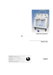
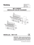
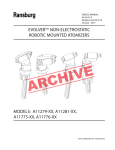
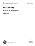
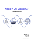
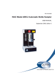
PRODUCT MANUAL
CS-11-01.2
Inline/Piggable
Modular Color Changer
MODEL: A12800-XX
IMPORTANT: Before using this equipment,
carefully read SAFETY PRECAUTIONS, starting on
page 1, and all instructions in this manual. Keep
this Service Manual for future reference.
Product Manual Price: $50.00
CS-11-01.2: Inline / Piggable Modular Color Changer
2
CONTENTS
Section 1: SAFETY
5-9
Safety Precautions
Hazards / Safeguards
Section 2: INTRODUCTION
10-14
General Description
Pre-Engineered Color Changer Assemblies
Color Changer Assembly Model
Identification / Parts List
Section 3: INSTALLATION
15-16
PCC Installation Procedures
Section 4: OPERATION
17-19
Color Changer Schematics
Grounding of the Color Changer
Fluid Inlet and Outlet Fittings
Air Pilot Hose
Fluid Output Hose
Assembly with Purge Block
Assembly with No Purge Block
Section 5: MAINTENANCE
20-24
Micro-Valve and Valve Seat Replacement
Test and Checkout Procedure for Color Changer
Tools and Optional Equipment
Recommended Spare Parts
Section 6: WARRANTY POLICIES
25
Limited Warranty
CS-11-01.2: Inline / Piggable Modular Color Changer
3
CS-11-01.2: Inline / Piggable Modular Color Changer
4
Section 1: SAFETY
Before operating, maintaining or servicing any Binks electrostatic coating system, read and understand all of the technical and safety literature for your Binks products. This manual contains information that is important for you to know
and understand.
This information relates to USER SAFETY and PREVENTING EQUIPMENT PROBLEMS. To help you
recognize this information, we use the following symbols:
CAUTION - states information that tells
how to prevent damage to equipment
or how to avoid a situation that might
cause minor injury.
WARNING - states information to alert
you to a situation that might cause serious injury if instructions are not followed.
While this manual lists standard specifications and service
procedures, some minor deviations may be found between
the literature and your equipment. Differences in local codes
and plant requirements, material delivery requirements, etc.,
make such variations inevitable. Compare this manual with
your system installation drawings and appropriate Binks
equipment manuals to reconcile such differences.
Careful study and continued use of this manual will provide a
better understanding of the equipment and process, resulting
in more efficient operation, longer trouble-free service and
faster, easier troubleshooting. If you do not have the manuals and safety literature for your Binks system, contact your
local Binks representative or Binks.
WARNING
•
The user MUST read and be familiar with the Safety Section in this manual and the Binks safety literature
therein identified.
•
This manual MUST be read and thoroughly understood by ALL personnel who operate , clean or maintain
this equipment! Special care should be taken to ensure that the WARNINGS and safety requirements for
operating and servicing the equipment are followed. The user should be aware of and adhere to ALL local
building and fire codes and ordinances as well as NFPA 33 SAFETY STANDARD, 2009 EDITION, prior to
installing, operating, and/or servicing this equipment.
•
The hazards shown on the following pages may occur during normal use of this equipment. Please read
the hazard chart beginning on page 6.
CS-11-01.2: Inline / Piggable Modular Color Changer
5
AREA
Spray Area
HAZARD
SAFEGUARDS
Fire Hazard
Follow These Guidelines
Improper or inadequate operation and
maintenance procedures will cause a fire
hazard.
Protection against inadvertent arcing that is
capable of causing fire or explosion is lost if
any safety interlocks are disabled during
operation. Frequent power supply shutdown indicates a problem in the system
requiring correction.
Fire extinguishing equipment must be present in the
spray area and test periodically.
Spray areas must be kept clean to prevent the accumulation of combustible residues.
Smoking must never be allowed in the spray area.
The high voltage supplied to the atomizer must be
turned off prior to cleaning, flushing or maintenance.
When using solvents for cleaning:
•
Those used for equipment flushing should have
flash points equal to or higher than those of the
coating material.
•
Those used for general cleaning must have flash
points above 1000F (37.80C).
Spray booth ventilation must be kept at the rates required by NFPA 33, 2009 Edition, OSHA and local
codes. Ventilation must be maintained during cleaning
operations using flammable or combustible solvents.
Electrostatic arcing must be prevented.
Non-factory replacement parts or unauthorized equipment modifications may cause fire or injury.
If used, a key switch bypass is intended for use only
during setup operations. Production should never be
done with safety interlocks disabled.
Never use equipment for use in waterborne installations to spray solvent based materials.
CS-11-01.2: Inline / Piggable Modular Color Changer
6
AREA
Spray Area
HAZARD
SAFEGUARDS
Explosion
Follow These Guidelines
Improper or inadequate operation and
maintenance procedures may cause an
explosion.
Protection against inadvertent arcing that is
capable of causing fire or explosion is lost if
any safety interlocks are disabled during
operation. Frequent power supply shutdown indicates a problem in the system
requiring correction.
Electrostatic arcing MUST be prevented.
All electrical equipment must be located outside Class I
or II, Division 1 or 2 hazardous areas, in accordance
with NFPA 33, 2009 Edition.
Test only in areas free of flammable or combustible
materials.
The current overload sensitivity (if equipped) MUST be
set as described in corresponding section of the equipment manual. Protection against inadvertent arcing
that is capable of causing fire or explosion is lost if the
current overload sensitivity is not properly set. Frequent power shutdown indicates a problem with the
system which requires correction.
Always turn the control panel off prior to flushing, cleaning, or working on spray system equipment.
Ensure that the control panel is interlocked with the
ventilation system and conveyor in accordance with
NFPA 33, 2009 Edition.
Have fire extinguishing equipment readily available and
tested periodically.
Spray Area
Explosion - Incompatible Materials
Follow These Guidelines
Halogenated hydrocarbon solvents for example: methylene chloride and 1,1,1,Trichloroethane are not chemically compatible with the aluminum that might be used in
many system components. The chemical
reaction caused by these solvents reacting
with aluminum can become violent and lead
to an equipment explosion.
Aluminum is widely used in other spray application
equipment - such as material pumps, regulators, triggering valves, etc. Halogenated hydrocarbon solvents
must never be used with aluminum equipment during
spraying, flushing, or cleaning. Read the label or data
sheet for the material you intend to spray. If in doubt
as to whether or not a coating or cleaning material is
compatible, contact your coating supplier. Any other
type of solvent may be used with aluminum equipment.
CS-11-01.2: Inline / Piggable Modular Color Changer
7
AREA
Spray Area / High Voltage Equipment
HAZARD
SAFEGUARDS
Electrical Discharge
Follow These Guidelines
There is a high voltage device that can induce an electrical charge on ungrounded
objects which is capable of igniting coating
materials.
Inadequate grounding will cause a spark
hazard. A spark can ignite many coating
materials and cause a fire or explosion.
Parts being sprayed must be supported on conveyors
or hangers and be grounded. The resistance between
the part and ground must not exceed 1 mega ohm.
All electrically conductive objects in the spray area, with
the exception of those objects required by the process
to be at high voltage, must be grounded.
Any person working in the spray area must be grounded.
Unless specifically approved for use in hazardous locations, the power supply and other electrical control
equipment must NOT be used in Class I, Division 1 or 2
locations.
Electrical Equipment
Electrical Discharge
Follow These Guidelines
High voltage equipment is utilized. Arcing
in areas of flammable or combustible materials may occur. Personnel are exposed to
high voltage during operation and maintenance.
All electrical equipment must be located outside Class I
or II, Division 1 or 2 hazardous areas. Refer to NFPA
33, 2009 Edition.
Turn the power supply OFF before working on the
equipment.
Protection against inadvertent arcing that
may cause a fire or explosion is lost if safety
circuits are disabled during operation.
Test only in areas free of flammable or combustible
material.
Frequent power supply shutdown indicates
a problem in the system which requires
correction.
Testing may require high voltage to be on, but only as
instructed.
An electrical arc can ignite coating materials
and cause a fire or explosion.
Production should never be done with the safety circuits disabled.
Before turning the high voltage on, make sure no objects are within the sparking distance.
CS-11-01.2: Inline / Piggable Modular Color Changer
8
AREA
Toxic Substances
HAZARD
SAFEGUARDS
Mechanical Hazard
Follow These Guidelines
Certain material may be harmful if inhaled,
or if there is contact with the skin.
Follow the requirements of the Material Safety Data
Sheet supplied by the coating manufacturer.
Adequate exhaust must be provided to keep the air free
of accumulations of toxic materials.
Use a mask or respirator whenever there is a chance of
inhaling sprayed materials. The mask must be compatible with the material being sprayed and its concentration. Equipment must be as prescribed by an industrial
hygienist or safety expert, and be NIOSH approved.
Robot Work Area
Mechanical Hazard
Follow These Guidelines
Improper use or maintenance can lead to
hazardous conditions, particularly from unexpected robot manipulator movement.
Applicator adjustments or maintenance should be done
after the robot is taken out of service. Do not adjust or
repair the applicator if the robot is operating or standing
ready to start.
Refer to robot operating instructions for the procedures
to take a robot out of service.
Follow all OSHA Lockout / Tagout procedures when
performing any maintenance.
All Areas
Improper / Inadequate Training
Follow These Guidelines
Improper operation or maintenance may
create a hazard.
Personnel must be given training in accordance with
the requirements of NFPA 33, 2009 Edition.
Personnel must be properly trained in the
use of this equipment.
Instructions and safety precautions must understood
prior to using this equipment.
Comply with appropriate codes governing ventilation,
fire protection, operation maintenance, and housekeeping. OSHA references are sections 1910.94 and
1910.107. Also refer to NFPA 33, 2009 Edition and
your insurance company requirements.
CS-11-01.2: Inline / Piggable Modular Color Changer
9
Section 2: INTRODUCTION
The Inline / Piggable Modular Color Changer assembly was designed for use with a pipe circulating system that can
also operate as a piggable fluid delivery systems. Made of stainless steel for corrosion resistance and built to stand up
under hard, continuous use. The PCC can be easily mounted and was designed for adaptability to the user’s needs.
SPECIFICATIONS - Environmental / Physical
Valve Size: Single Valve (See “Mounting Color Changer” figures in the “Installation” section)
Valve Block Assembly Weight: Single Valve Assembly: .45 lbs. (205 grams)
Assembly Weight with 3/4” Tube: .95 lbs. (430 grams)
Purge Block Assembly Weight: .96 lbs. (435 grams)
Spacer Block Weight: .936 Block: .20 lbs. (91 grams)
.437 Block: .09 lbs. (41 grams)
Spacer Plate Weight: .936 Spacer Plate: .04 lbs. (18.1 grams)
.437 Spacer Plate: .02 lbs. (9.1 grams)
Operating Pressure: Fluid: 300 psi max. (20.68 bar)
Trigger Tube: 5/32” (4mm) OD
Micro-Valve Air Actuating Pressure: 75-120 psi (5.2-8.3 bar)
Average Flow Rate: 75 Fl. Oz./2200cc per min. @ 75 psi (50 centiposee)
Maximum Number of Colors: 20
Construction Materials: Stainless Steel, UHMW, Fluoropolymer elastomers, and Acetal
CS-11-01.2: Inline / Piggable Modular Color Changer
10
PRE-ENGINEERED COLOR CHANGER ASSEMBLIES
The following is for “Pre-Engineered” Color Changer assemblies. Please reference selection chart for the changer assembly number.
CS-11-01.2: Inline / Piggable Modular Color Changer
11
COLOR CHANGER ASSEMBLY SELECTION GUIDE
When ordering, use A12800 - A, B, or C as indicated by Table A thru C. Four digits must follow the basic part number.
For example:
INLINE / PIGGABLE MODULAR COLOR CHANGER PARTS LIST
ITEM
QTY
PART NUMBER
DESCRIPTION
1
2
Table A, Item A
Table B, Item E
Plate and Pipe Assembly (Tabulated)
Table A, Item A
A12739-00
Color Block (Piggable)
3
Table A, Item B
Table B, Item J
Spacer Block
4
Table A, Item B
Table B, Item K
Spacer Plate
5
Table A, Item A
79001-05
O-Ring, Solvent Proof *****
6
Table A, Item H
79001-06
O-Ring, Solvent Proof *****
7
1
A12759-00
End Block, Outlet
8
Table C, Item M
A12757-00
End Block, Inlet
9
Table B, Item G
A12744-XX
Threaded Rod
10
2
78079-00
Fitting, 7/16-20 X 3/8 NPS******
11
4
78405-06
Flat Washer, Stainless, 5/16
12
4
77588-07
Lock Washer
13
4
A12765-00
Hex Nut, 5/16-18, SS ********
14
Table A, Item A
77367-00
Valve Seat Assembly ****
15
Table A, Item A
78949-00
Valve Assembly (Non-Repairable) ***
16
Table A, Item A
79001-30
O-Ring, Solvent Proof *****
17
Table A, Item A
77516-04
Collet, 4mm
18
Table B, Item F
A12772-01
Screw, SHCS, #10-24
19
Table A, Item L
A12727-00
Screw, SHCS, Shut-off Valve Assembly
20
Table A, Item I
A10766-00
Tool, Valve Seat Removal (Not Shown)
21
Table A, Item I
A10756-00
Tool, Valve Removal (Not Shown)
23
Table A, Item D
76566-56C
Screw, SHCSm 1/4-20 X 1.75, SS
24
Table A, Item D
76566-64C
Screw, SHCS, 1/4-20 X 2.00, SS
26
Table C, Item N
27
1
*
A12827-00
Purge Block Assembly *******
CS-11-01
Service Manual
When bui l di ng opti on wi th one col or, threa ded rod l ength to be 5.03 l ong (2) pi eces .
**
Ea ch a s s embl y requi res 2 pi eces ea ch of threa ded rod cut l engths , deburr ends of rod.
***
Torque to 15-20 l bs •i n a fter va l ve i s down (1.7-2.3 Nm).
****
Torque to 15-20 l bs •i n. (1.7-2.3 Nm).
*****
Appl y A11545-00 Petrol a tum jel l onto a l l o-ri ngs before i ns ta l l a ti on.
******
Torque to 30 l bs •ft. (40.67 Nm).
*******
When orderi ng thi s opti on, a dd 2.6" to l ength of "G" i n Ta bl e B.
(Exa mpl e: 1.91 + (2.12 X number of col ors ) + 2.6)
******** Torque 30-50 l bs •i n (.212/3.53 Nm)
CS-11-01.2: Inline / Piggable Modular Color Changer
12
COLOR CHANGER ASSEMBLY SELECTION GUIDE (Continued)
TABLE A - NUMBER OF COLOR BLOCKS
DASH NO. DESCRIPTION
"A" QTY
"B" QTY
"D" QTY
"H" QTY
"L" QTY
01
Number of Color Blocks
1
0
2
2
1
02
Number of Color Blocks
2
1
4
3
2
03
Number of Color Blocks
3
2
6
4
3
04
Number of Color Blocks
4
3
8
5
4
05
Number of Color Blocks
5
4
10
6
5
06
Number of Color Blocks
6
5
12
7
6
07
Number of Color Blocks
7
6
14
8
7
08
Number of Color Blocks
8
7
16
9
8
09
Number of Color Blocks
9
8
18
10
9
10
Number of Color Blocks
10
9
20
11
10
11
Number of Color Blocks
11
10
22
12
11
12
Number of Color Blocks
12
11
24
13
12
13
Number of Color Blocks
13
12
26
14
13
14
Number of Color Blocks
14
13
28
15
14
15
Number of Color Blocks
15
14
30
16
15
16
Number of Color Blocks
16
15
32
17
16
17
Number of Color Blocks
17
16
34
18
17
18
Number of Color Blocks
18
17
36
19
18
19
Number of Color Blocks
19
18
38
20
19
20
Number of Color Blocks
20
19
40
21
20
TABLE B - FLUID SUPPLY SIZE
DASH NO. DESCRIPTION
01
1/2" Standard
"E"
A12740-01
"F"
0
"J"
--
"K"
--
--
--
02
3/4" Standard
A12740-02
0
03
1" Standard
A12740-03
2
A12742-00 A12762-00
04
1 1/2" Standard
A12740-04
2
A12742-00 A12762-00
05
1/2" Standard
A12740-01
2
A12861-00 A12860-00
06
3/4" Standard
A12740-02
2
A12861-00 A12860-00
"G" LENGTH OF THREADED ROD
1.91 + (2.12 X Number of Colors) Pipe Assemblies
will be on 2 1/16" Centers ****
1.91 + (2.12 X Number of Colors) Pipe Assemblies
will be on 2 1/16" Centers
1.91 + (3.06 X Number of Colors) Pipe Assemblies
will be on 3" Centers ***
1.91 + (3.06 X Number of Colors) Pipe Assemblies
will be on 3" Centers ***
1.91 + (2.48 X Number of Colors) Pipe Assemblies
will be on 2 1/2" Centers
1.91 + (2.48 X Number of Colors) Pipe Assemblies
will be on 2 1/2" Centers
TABLE C
DASH NO.
DESCRIPTION
00
None
01
Purge Block Assembly *******
"M"
1
0
"N"
0
1
CS-11-01.2: Inline / Piggable Modular Color Changer
13
COLOR CHANGER ASSEMBLY SELECTION GUIDE (Continued)
A12827-00 PURGE BLOCK ASSEMBLY
ITEM
QTY
PART NUMBER
DESCRIPTION
1
1
A12754-00
Purge Block
2
2
77367-00
Valve Seat Assembly **
3
2
78949-00
Valve Assembly *
4
2
A12727-00
Shut-off Valve Assembly
5
2
79001-30
O-Ring, Solvent Proof
6
2
77516-04
Collet, 4mm
7
2
79001-06
O-Ring, Solvent Proof
8
1
A12829-00
Purge Block End Plate Assembly
9
2
78079-00
Ftg, 7/16-20 X 3/8 NPA ***
*
Torque to 15-20 lbs•in aŌer valve is down.
**
Torque to 15-20 lbs•in (1.7-2.3 Nm).
***
Torque to 30 lbs•Ō (40.67 Nm).
4
Apply A11545-00 Petrolatum jell to all o-rings prior to installaƟon.
CS-11-01.2: Inline / Piggable Modular Color Changer
14
Section 3: INSTALLATION
This information is intended ONLY to indicate the general installation parameters of this product and, where applicable,
its working relationship to other Binks system components in typical use.
Each installation is unique and should be directed by an authorized Binks representative or conducted using the Binks
installation drawings provided for your particular installation.
COLOR CHANGER INSTALLATION PROCEDURES
Determine Location for Color Changer
The color changer should be located as close as possible to the spray device in order to save paint and solvent. If possible, use an
enclosure to protect the color changer from airborne paints and solvents.
Calculate Footprint of Color Changer (See Mounting Single Valve Color Changer Figure)
To calculate the footprint of the color changer add:
1.
The dimension of the purge assembly (if used).
2.
The dimension(s) of the color block(s) used to create the desired number of color valves.
3.
The dimension of the inlet/outlet block.
Dimension of Purge Assembly:
2.60” (66.04mm)
Dimension of Color Block Assembly:
2.064” (52.43mm)
Dimension of Spacer Block:
.936”(23.77mm) and .437 (11.10mm)
Dimension of Inlet or Outlet Block:
.53”(13.46mm)
Example of 1/2”and 3/4”Pipe Assembly with 2 Color Blocks (No Spacers):
Inlet Block
.53”
.53”+ .53”+ 2.064”+ 2.064”= 5.188”(131.7mm)
Outlet Block
.53”
NOTE: If adding Purge Block Assembly add 2.600”
#1 Color Block
2.064”
5.188”+ 2.600”= 7.988”(197.82mm)
#2 Color Block
2.064
(NOTE: These pipe center lines will be 2 1/16”Center to Center)
Example of 1”and 1 1/2”Pipe Assembly with 2 Color Blocks with .437 Spacer Block:
Inlet Block
.53”
.53”+ .53”+ .437”+ 2.064”+ 2.064”= 5.625”(142.88mm)
Outlet Block
.53”
(NOTE: If adding Purge Block Assembly add 2.600”)
#1 Color Block
2.064”
5.625”+ 2.600” = 7.225”(183.52mm)
#2 Color Block
2.064”
(NOTE: These pipe center lines will be 2 1/2”center to center)
Spacer Block
.437”
Purge Block Assembly
2.600”
CS-11-01.2: Inline / Piggable Modular Color Changer
15
COLOR CHANGER INSTALLATION PROCEDURES (Continued)
Mounting The Color Changer
The mounting configuration is as follows: Single Valve (See Figures Above)
NOTE - In and out plates are tapped 7/16-20 for “AN” taper fitting.
NOTE - The .936 wide spacer plates (A12742-00) are to be used with 1” or larger pipe assemblies to insure clearance distance of sanitary clamps.
NOTE - The .437 wide spacer blocks (A12861-00) are to be used if retrofitting older Binks Modular Color Change
Systems requiring 2 1/2” (63.5mm) center to center spacing of pipe assemblies.
CS-11-01.2: Inline / Piggable Modular Color Changer
16
Section 3: OPERATION
This information is intended ONLY to indicate the general installation parameters of this product and, where applicable,
its working relationship to other Binks system components in typical use.
Each installation is unique and should be directed by an authorized Binks representative or conducted using the Binks
installation drawings provided for your particular installation.
The assembly consists of modules attached to each other. Modules may be added or removed from the assembly as desired. If, for
instance, the number of required materials increases, the assembly can be expanded by adding additional modules. Each module can
also be individually serviced. The Modular Color Changer is recommended for use with waterborne or solventborne paints.
CS-11-01.2: Inline / Piggable Modular Color Changer
17
GROUNDING OF THE COLOR CHANGER
WARNING
•
The color changer MUST be properly grounded. Proper grounding (as described below) will prevent static
charge build-up and possible discharge from the color changer.
GROUNDING OF THE COLOR CHANGERS
For safety, the color changer MUST be grounded. Using a 12-gauge wire, ground the output plate of the color changer to a true earth
ground. Using an ohm meter, check for ground, testing the earth ground to the purge assembly top plate. The resistance should be 10
ohms or less.
FLUID INLET AND OUTLET FITTINGS
The in and out of the pipe assemblies have standard sanitary fittings.
NOTE - In and out hoses CAN be reversed on the color changer.
AIR PILOT HOSE
Each color changer valve requires a 5/32”(4mm) pilot hose to activate the color valve.
FLUID OUTPUT HOSE
The fluid output hose of the color changer has a 3/8”NPS (M) fitting. For safety and solvent savings, it is recommended that a PFA
fluoroethylene hose be used between the color changer and the spray device.
CS-11-01.2: Inline / Piggable Modular Color Changer
18
COLOR CHANGER ASSEMBLY
Assembly with Purge Block
Assembly with No Purge Block
NOTE - Microvalve Weep Holes
These holes will give an indication of fluid valve failure. In the event of the fluid seal failure, paint or solvent will be seen coming out
of this hole. In the event that the air seal for the piston fails, air will be heard or felt coming from this hole.
CS-11-01.2: Inline / Piggable Modular Color Changer
19
Section 4: MAINTENANCE
CAUTION
•
Before attempting to remove BOTH the Microvalve Assembly (78949-00) and the Valve Seat Assembly
(77367-00), first turn the Shut-Off Valve (A11591-11) counter-clockwise to its open position. Then relieve
and flush the main inlet circulating paint line.
NOTE—If ONLY the Microvalve Assembly (78949-00) is to be removed or replaced, turn the Shut-Off Valve (A11591-00) clockwise to it’s closed position. Then relieve and flush the microvalve or downstream side of the color changer.
1.
Microvalve Assembly (78949-00) - Using the valve
removal tool (A10756-00 or A11922-00), engage the
four (4) pins of the tool into the four (4) pin holes of
the valve assembly. Turn the assembly counterclockwise until removed).
2.
Valve Seat Assembly (77367-00) - If required to
remove the valve seat assembly, use the valve seat
removal tool (A10766-00) turning the valve seat
counter-clockwise until removed. Clean and inspect
the valve body and o-rings for defects, replace if necessary.
3.
Seat and Microvalve Installation—If valve seat was
removed, lightly lubricate the o-ring on the seat assembly with petroleum jelly. Install valve seat and
tighten to 15-20 lbs•in (1.7-2.3 Nm) of torque. Lightly
lubricate the o-rings on the microvalve assembly.
Install the valve and tighten to 15-20 lbs•in (1.7-2.3
Nm) of torque after valve is down.
CS-11-01.2: Inline / Piggable Modular Color Changer
20
TEST AND CHECK OUT PROCEDURE FOR COLOR CHANGER
B.
With ball valves #1 and #3 in the Off position, push and
release the button on the pneumatic valve #5, triggering
the microvalve assembly (78949-00) On and Off.
C.
Visually inspect the movement of the valve and check for
air leaks from the weep hole on the color valve body. If
air is leaking, repair or replace valve assembly (7894900). Check for leaks between the pipe/plate assembly
and color valve block. Tighten screws or replace o-ring if
necessary.
D.
With ball valves #1 and #3 in the On (open) position, push
and release the button on the pneumatic valve #5 triggering the microvalve assembly (78949-00) On and Off.
Check for a crisp and sharp actuation of air flow through
the output of the #1 ball valve. If valve is sluggish, repair
or replace valve assembly (78949-00).
TEST AND CHECK OUT PROCEDURE FOR COLOR
CHANGER
Step 1: Test Setup
A.
Connect a main air line to the regulator #4.
B.
Attach the output of #4 to a push button, manually operated pneumatic On/Off valve #5 and #3, two-way manual
ball valve. Attach a 5/32” hose from the output of #5 to
pilot connection for the color valve.
C.
Attach the output of #3 the sanitary fitting input of the
valve. Plug the opposite sanitary fitting of valve.
D.
Attach pipe tee, gage, #2 and two-way ball valve assembly #1 to the output of the color changer. Plug off other
side.
Step 3: Testing Valve Body Leak Test
A.
With ball valve #3 in the On (open) position and valve #1
In the Off position, push and release the button on the
pneumatic valve #5 triggering the microvalve assembly
(78949-00) On and Off several times.
B.
Check the pressure gage reading on the #2 assembly.
This should be within 5 psi of the pressure of the set pressure on regulator #4. The pressure should remain until
the valve #1 is returned to the open position. If the pressure does not remain, check all fittings, hardware, and orings on the valve body and plate assembly.
Step 2: Testing Color Valve Assembly
A.
Set output pressure of regulator #4 to 90-100 psi.
Step 4: Testing Microvalve and Valve Seat Assemblies
NOTE—Turn the shutoff valve #6 counter-clockwise to the
OPEN position.
A.
With ball valve #1 in the On position, and valve #3 in the
On position, push and release the button on the pneumatic valve #5 triggering the microvalve assembly (7894900) On and Off several times.
B.
Close the 2-way ball valve on the #1 assembly. The
pressure should remain 0 psi.
If the pressure is greater than 0 psi, the valve seat assembly
(77367-00) should be replaced.
WARNING
•
NEVER wrap the equipment in plastic to keep it clean. A surface charge may build-up on the plastic
surface and discharge to the nearest grounded object. Efficiency of the equipment will also be reduced and damage or failure of the equipment’s components may occur. WRAPPING THE EQUPMENT in plastic will void warranty.
CS-11-01.2: Inline / Piggable Modular Color Changer
21
VALVE TESTING ASSEMBLY
Valve Testing Assembly
Microvalve Weep Holes
These holes will give an indication of fluid valve failure. In the event of the fluid seal failure, paint or solvent will be seen coming out of
this hole. In the event that the air seal for the piston fails, air will be heard or felt coming from this hole.
CS-11-01.2: Inline / Piggable Modular Color Changer
22
OPTIONAL EQUIPMENT
TOOLS AND OPTIONAL EQUIPMENT
78949-00 VALVE ASSEMBLY / 77367-00 SEAT ASSEMBLY
REPLACEMENT PARTS
ITEM
PART NUMBER
1
2
3
79001-01
79001-02
79001-04
DESCRIPTION
O-Ring (Solventproof)
O-Ring (Solventproof)
O-Ring (Solventproof)
77620-00 VALVE PLUG KIT
ITEM
PART
NUMBER DESCRIPTION
1
2
79244-00 Plug
79001-19 O-Ring (Solventproof)
3
4
79001-14 O-Ring (Solventproof)
77618-00 Plug Seat
CS-11-01.2: Inline / Piggable Modular Color Changer
23
RECOMMENDED SPARE PARTS
RECOMMENDED SPARE PARTS
PART NUMBER
DESCRIPTION
QTY
A12727-00
Shut-off Valve Assembly
4
78949-00
Valve Assembly
2
77367-00
77516-04
Valve Seat Assembly
Collet, 4mm
2
2-4
CS-11-01.2: Inline / Piggable Modular Color Changer
24
WARRANTY POLICIES
LIMITED WARRANTY
Binks will replace of repair without charge any part/or equipment that fails within the specified time (see below) because
of faulty workmanship or material, provided that the equipment has been used and maintained in accordance with Binks'
written safety and operating instructions, and has been used under normal operating conditions. Normal wear items are
excluded.
THE USE OF OTHER THAN BINKS APPROVED PARTS VOIDS ALL WARRANTIES.
SPARE PARTS: One hundred and eighty (180) days from date of purchase, except for rebuilt parts (any part number
ending in "R") for which the warranty period is ninety (90) days.
EQUIPMENT: When purchased as a complete unit, is one (1) year from date of purchase.
WRAPPING THE APPLICATOR IN PLASTIC WILL VOID THIS WARRANTY.
BINKS’ ONLY OBLIGATION UNDER THIS WARRANTY IS TO REPLACE PARTS THAT HAVE FAILED BECAUSE
OF FAULTY WORKMANSHIP OR MATERIALS. THERE ARE NO IMPLIED WARRANTIES NOR WARRANTIES OF
EITHER MERCHANTABILITY OR FITNESS FOR A PARTICULAR PURPOSE. BINKS ASSUMES NO LIABILITY FOR
INJURY, DAMAGE TO PROPERTY OR FOR CONSEQUENTIAL DAMAGES FOR LOSS OF GOODWILL OR PRODUCTION OR INCOME, WHICH RESULT FROM USE OR MISUSE OF THE EQUIPMENT BY PURCHASER OR OTHERS.
EXCLUSIONS:
If, in Bink’s opinion the warranty item in question, or other items damaged by this part was improperly installed, operated
or maintained, Binks will assume NO responsibility for repair or replacement of the item or items. The purchaser, therefore will assume all responsibility for any cost of repair or replacement and service related costs if applicable.
CS-11-01.2: Inline / Piggable Modular Color Changer
25
Product Manual Price: $50.00 (U.S.)
Manufacturing
1910 North Wayne Street
Angola, Indiana 46703-9100
Telephone: 260-665-8800
Fax: 260-665-8516
Technical Service - Assistance
320 Phillips Ave.
Toledo, Ohio 43612-1493
Telephone (toll free): 800-233-3366
Telephone: 419-470-2021
Fax: 419-470-2233
Technical Support Representatives can direct you to the appropriate telephone number for ordering spare parts.
Form No. CS-11-01
© 2011 Binks All rights reserved.
Litho in U.S.A.
Models and specifications subject to change without notice.
06/11
CS-11-01.2: Inline / Piggable Modular Color Changer
26