1
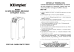
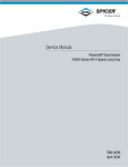
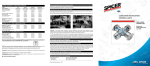
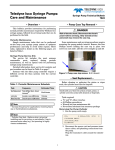
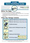
Service Manual
Industrial Planetary Axles - Heavy
Planetary Rigid
25D
80-1041
6/13
ASM-0116
November 2003
5.62 Ø B.C. Ref.
[142.7]
-A-
2.8125
[71.4375]
.309-.318 [7.85-8.07] Ø
1.25 [31.8] DEEP
.44 Ø X 90° CSK
.3750-16 UNC-3B THD
.75 [19.0] DEEP
3 HOLES SPACED AS SHOWN
Ø.010 [0.25] M B M A
UNLESS OTHERWISE SPECIFIED:
.xx[.x] = ±.03[.8]
.xxx[.xx] = ±.010[.25]
.xxxx[.xxx] = BASIC
ANGLES = ±1°
Must be free of burrs and sharp edges
1.4062
[35.7175]
-B-
Internal Gear Hub Modification
Ref Internal Gear And Hub Assembly
2.4357
[61.8668]
Modified Internal Gear
and Hub Assembly
Nut-Bearing Adjusting
17C-624H 3 Places per wheel end
(. 375-16 UNC-2B THD 1. 50 [38.1] long)
Spindle
Wheel Bearing Adjustment
1. Before wheel bearing adjustment is made, it is imperative all tapered bearings
cones and cups be pressed to fully seated position. Do not depend on the wheel
bearing adjusting nut to “shoulder” tapered bearings cups and cones.
2. Coat washer face of nut and spindle threads with brush-applied MS-260 lubricant.
(Anti-Seize or Never-Seez)
3. Install nut and tighten to 1000 LBF-FT [1356 NM] torque. Shock internal gear hub with
heavy bar or mallet. Rotate wheel hub 2 to 3 times. Repeat shocking and rotating.
Recheck nut torque - if nut moves, retorque to 1000 LBF-FT [1356 NM] and repeat
shocking and rotating as above. Continue above procedure until 1000 LBF-FT [1356 NM]
does not advance nut.
4. Loosen nut ¼ to ½ turn, shock to loosen and measure the no-load rolling torque (normally
25-100 LBF-FT [34-135 NM]).
5. Torque to 700 LBF-FT [949 NM], then advance nut until 3 holes in nut line up with tapped holes
in internal gear hub.
6. Check rolling torque - must be in the range of:
Used bearings - 5-15 LBF-FT [7-20 NM] above no-load rolling torque
New bearings - 20-80 LBF-FT [27-108 NM] above no-load rolling torque
Nut-Bearing Adjusting
7. If over the maximum rolling torque, reduce nut torque as required to obtain the 5-15/20-80 LBF-FT
[7-20/27-108 NM] but not less than 400 LBF-FT [542 NM] on nut. If this occurs, remove nut and
internal gear hub. Rotate internal gear hub 3-4 spline teeth or reverse nut and reassemble. Repeat
bearing preload procedure.
8. If under the minimum rolling torque, increase nut torque until preload is in the 5-15/20-80 LBF-FT
[7-20/27-108 NM] rolling torque range with nut holes aligned. However, do not exceed 1400 LBF-FT
[1898 NM].
9. Loctite the capscrew threads with Loctite no 262 and install at 35-40 LBF-FT [48-54 NM] tightening torque.
Allied PN X-203540
Use torque wrench and adaptor (Allied PN X-203540), properly centered, or other
appropriate measuring device to determine “no-load” rolling torque.
Copyright 2010 Dana Holding Corporation
All content is subject to copyright by Dana and may not
be reproduced in whole or in part by any means,
electronic or otherwise, without prior written approval.
THIS INFORMATION IS NOT INTENDED FOR SALE OR
RESALE, AND THIS NOTICE MUST REMAIN ON ALL
COPIES.
For product inquiries or support,
visit www.dana.com or call 419-887-6445
For other service publications,
visit www.SpicerParts.com/literature.asp
For online service parts ordering,
visit www.SpicerParts.com/order.asp