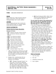
1
DRIVEABILITY—MALFUNCTION INDICATOR LAMP (MIL) ILLUMINATED—DIAGNOSTIC TROUBLE CODES (DTCS) P0340, P1380, P1381, OR P1383 IN MEMORY—VEHICLES WITH 2.0L ZETEC ENGINE Article No. 03-15-14 FORD: 1998-2000 CONTOUR 1998-2003 ESCORT ZX2 MERCURY: 1998-2000 MYSTIQUE 1999-2002 COUGAR This article supersedes TSB’s 98-9-8 and 99-10-5. ISSUE The Malfunction Indicator Lamp (MIL) may be illuminated and Diagnostic Trouble Codes (DTCs) P1380, P1381, P1383, and/or P0340 may be stored in memory. The vehicle may also have a rough idle or reduced power condition, and/or may stall at an idle. NOTE IF CODES P1380, P1381, OR P1383 ARE NOT PRESENT IN KOER, VCT AND VALVETRAIN COMPONENTS ARE FUNCTIONING AND ARE PROPERLY ADJUSTED. FAULT CANNOT BE DUPLICATED OR IDENTIFIED AT THIS TIME. 1. If DTC P1381 or P1383 is present in KOER, install 104-pin breakout box. ACTION 2. Refer to the following Service Information for diagnostic tips and repair procedures. Run engine to normal operating temperature. ECT/CHT = 190-240°F (87-115°C). 3. Select and monitor Parameter Identification Displays (PID): NGS (PIDs) CAMERR, CAMDCR, RCAM, and RPM. WDS (PIDS) VCTADV, VCTADVERR, VCTDC, and RPM. 4. Insert one end of a banana plug jumper into VCT Pin 44 (Pin 45 for vehicles with return-less fuel system) breakout box. 5. Increase engine speed to 2500 rpm and touch the other end of the jumper to PWR GND Pin 103 for approximately 1 second and release. 6. While maintaining 2500 rpm, monitor RCAM (NGS) / VCTADV (WDS) and repeat Step 5: 1 second on, 1 second off for 20 to 30 cycles. 7. Verify that RCAM/ VCTADV (WDS) changes from -15 to +45 (approximately) when Pin 103 is connected. 8. Turn ignition key to locked position and then restart engine. 9. Monitor PIDs previously selected. Vary engine speed from idle to 3000 rpm. If the cycling procedure succeeded, CAMERR (NGS) / VCTADVERR (WDS) will remain zero and RCAM (NGS) / VCTADV (WDS) will vary with rpm. SERVICE INFORMATION Inspect the following areas to help diagnose condition. • Variable Camshaft Timing (VCT) control system stuck with a machining chip • VCT hollow oil feed bolt being plugged with debris • A damaged Variable Camshaft tone ring • Incorrect base engine timing • On automatic transmission vehicles only, the flex-plate may be broken • Excessive crankshaft end-play • Mis-machined Cylinder Head NOTE PROCEED WITH THIS PROCEDURE ONLY IF DTCs P1381, P1383 OR P0340 ARE PRESENT IN KOER AND P1380 IS NOT PRESENT. IF P1380 IS PRESENT, REFER TO POWERTRAIN CONTROL/EMISSIONS DIAGNOSIS (PC/ED) SERVICE MANUAL. NOTE: The information in Technical Service Bulletins is intended for use by trained, professional technicians with the knowledge, tools, and equipment to do the job properly and safely. It informs these technicians of conditions that may occur on some vehicles, or provides information that could assist in proper vehicle service. The procedures should not be performed by “do-it-yourselfers”. Do not assume that a condition described affects your car or truck. Contact a Ford, Lincoln, or Mercury dealership to determine whether the Bulletin applies to your vehicle. Copyright 2003 Ford Motor Company PAGE 1 Article No. 03-15-14 Cont’d. NGS PIDs 10. If the cycling procedure succeeded: a. Clear codes. b. Change oil and filter and restore the vehicle. NOTE VEHICLES WITH A VARIABLE CAMSHAFT USE FORD OIL FILTER FL-2005, THIS OIL FILTER HAS AN INTERNAL CHECK VALVE THAT KEEPS THE EXHAUST VALVE CLOSED, WHEN THE ENGINE IS OFF, THIS WILL PREVENT ANY HARD START, OVER-FUELING OR FLOODING CONDITIONS ON INITIAL START UP (FIGURE 1). WDS PIDs UNITS --RCAM VCTA VCTADV DEGREES° MODE ON/OFF CAMERR VCTADVERR DEGREES° CAMDCR VCTDC PERCENT % VCTENA VCTSYS NGS = MODE ON/OFF WDS = MODE OL/CL (OL=OPEN LOOP) (CL=CLOSE LOOP) Parameter Identification Displays (PIDs) Relevant To VCT: NOTE VEHICLES WITH A VARIABLE CAMSHAFT RUN ON A MINIMUM OIL PRESSURE OF 50 PSI. REGARDLESS, OF THE ENGINE TEMPERATURE. 11. If VCT remains disabled at 3000 rpm (RCAM does not increase from idle reading), refer to PC/ED Service Manual. 1. CAMDCR (NGS) / VCTDC (WDS) = (0 to 99%) is the On-time of the VCT solenoid as requested by the PCM (see Figure 2). 2. CAMERR (NGS) / VCTADVERR (WDS) = (0° to 30°) is how many degrees the exhaust cam is ’out’ from the requested position. Values “+” mean the cam is not retarded enough and values “-” indicate the cam is over retarded (see Figure 3). 3. -RCAM (NGS) / VCTADV (WDS) = (-15° to +45°) represents actual position of the cam relative to the crankshaft (see Figure 4). Comparison chart on VCT PIDs NGS (New Generation Start Tester) and WDS (World Wide Diagnostic System). Normal PID Values (Approximate): Normal PID Values (Approximate) NGS PIDs WDS PIDs UNITS Warm At Idle 1500 RPM 4566 RPM --RCAM VCTA VCTADV VCTADV DEGREES° MODE ON/OFF (-) 15.00 OFF (+) 5.00 ON (+) 45.00 ON CAMERR VCTADVERR DEGREES° (+ OR -) 0 (+ OR -) 0 (+ OR -) 0 CAMDCR VCTDC PERCENT % (+ OR -) 0 (+) 30 (+) 50 VCTENA VCTSYS NGS = MODE ON/OFF WDS = MODE OL/CL (OL = OPEN LOOP) (CL = CLOSE LOOP) OFF ON/OFF ON OL OL/CL CL PAGE 2 Article No. 03-15-14 Cont’d. DTC(s): P1380 - VCT Solenoid Malfunction: Indicates a VCT circuit failure between the PCM and the VCT solenoid, or possible VCT solenoid failure. Check for 3-6 ohms resistance at the VCT Solenoid with the connector disconnected. Check for 12 volts power at the VCT harness, check continuity at the VCT ground and PCM driver. Consult the appropriate Electrical and Vacuum Troubleshooting Manual (EVTM) for circuit location and description (see Figure 5). P1381, P1383 & P0340 - VCT Over Advanced/Retarded: Indicates the exhaust camshaft would not advance/retard to the position requested by the PCM. These are the following possibilities: 1. The VCT is not moving the Exhaust Camshaft or possible bad VCT Solenoid. 2. The VCT is not moving the Exhaust Camshaft, possible bad Sprocket or sticking Sprocket. 3. The VCT is not moving the Exhaust Camshaft, possible low oil pressure, on VCT systems the engine has to have a minimum of 50 PSI. 4. The VCT is not moving the Exhaust Camshaft, possible wrong oil weight, contaminated oil, or wrong oil filter. Oil filter recommended is FL-2005. 5. The Camshaft Sensor is not reading the correct synchronization from the Camshaft, Possible damaged Tone Ring (see Figure 8). P1381 - VCT Over-Advanced: Indicates the exhaust camshaft would not retard to the position requested by the PCM. These are the following possibilities: 1. The VCT is not moving the Exhaust Camshaft, possible bad VCT Solenoid. 2. The VCT is not moving the Exhaust Camshaft possible bad Sprocket, sticking Sprocket. 3. The VCT is not moving the Exhaust Camshaft, possible low oil pressure, on VCT systems the engine has to have a minimum of 50 PSI. 4. The VCT is not moving the Exhaust Camshaft, possible wrong oil weight, contaminated oil, or wrong oil filter. Oil filter recommended is FL-2005 (see Figure 6). P1383 - VCT Over-Retarded: Indicates The Exhaust Camshaft Would Not Advance (Return) To The Position Requested By The PCM. 1. The VCT is not moving the Exhaust Camshaft, possible bad VCT Solenoid. 2. The VCT is not moving the Exhaust Camshaft, possible bad Sprocket or sticking Sprocket. 3. 4. The VCT is not moving the Exhaust Camshaft, possible low oil pressure, on VCT systems the engine has to have a minimum of 50 PSI. The VCT is not moving the Exhaust Camshaft, possible wrong oil weight, contaminated oil, or wrong oil filter. Oil filter recommended is FL-2005 (see Figure 7). P0340 - Runs Rough At Idle - Cranks No Start Starts & Stalls At Idle: When diagnosing this concerns, unplug the Camshaft position sensor, if the vehicle runs o.k. Look for a damaged Exhaust Camshaft Position Sensor Tone ring, refer to Figure 8 and check the tone ring alignment. For rough idle, cranks/no start, stall at idle or DTC codes P0340, P1383 or P1381, inspect for a broken Flex Plate or Monitor the PIDs on the NGS/WDS (see Figure 9). OVERVIEW ENGINE COMPONENTS (see Figures10-14). 1. SPROCKET (Figure 10). 2. EXHAUST RETAINER BOLT AND TOOL No # (Figure 11 and Figure 12). 3. VCT SOLENOID (Figure 13). 4. TOP DEAD CENTER AND TIMING PEG ALIGNMENT (Figure 14). PAGE 3 Article No. 03-15-14 Cont’d. OTHER APPLICABLE ARTICLES: 99-13-8, 00-3-7 SUPERSEDES: 98-9-8, 99-10-5 WARRANTY STATUS: INFORMATION ONLY Figure 1 - Article 03-15-14 Figure 2 - Article 03-15-14 PAGE 4 Article No. 03-15-14 Cont’d. Figure 3 - Article 03-15-14 Figure 4 - Article 03-15-14 PAGE 5 Article No. 03-15-14 Cont’d. Figure 5 - Article 03-15-14 Figure 6 - Article 03-15-14 PAGE 6 Article No. 03-15-14 Cont’d. Figure 7 - Article 03-15-14 Figure 8 - Article 03-15-14 PAGE 7 Figure 9 - Article 03-15-14 PAGE 8 Figure 10 - Article 03-15-14 Figure 11 - Article 03-15-14 PAGE 9 Figure 12 - Article 03-15-14 PAGE 10 Figure 13 - Article 03-15-14 Figure 14 - Article 03-15-14 PAGE 11