1
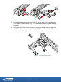
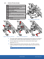
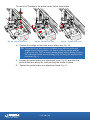
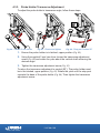
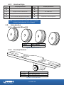
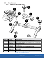
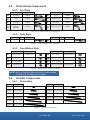
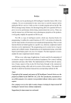
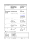
User Manual
Manual Magnetic Scanner
Safety Warnings / Precautions
KEEP THIS MANUAL – DO NOT LOSE
THIS MANUAL IS PART OF THE MICROBE AND MUST BE RETAINED FOR THE LIFE
OF THE PRODUCT. PASS ON TO SUBSEQUENT OWNERS.
Ensure any amendments are incorporated with this document.
DANGER! The MICROBE is designed for a specific use. Using the
MICROBE outside of its intended use could cause damage to the product.
Read and understand this manual before using.
WARNING! Can be harmful to pacemaker and ICD wearers. Stay
at least 25 cm (10 in) away.
WARNING! Do NOT operate scanner in an explosive environment.
Do NOT operate scanner in the presence of volatile substances.
The WEEE symbol indicates that the product must not be disposed of as
unsorted municipal waste, but should be collected separately.
DISTRIBUTOR:
MANUFACTURER:
Jireh Industries Ltd.
53158 Range Road 224
Ardrossan, Alberta, Canada
T8E 2K4
Phone: (780) 922-4534
Fax:
(780) 922-5766
www.jireh-industries.com
PAGE i of iv
BT0179 Rev 02.02
Table of Contents
1.Introduction 1.1.
1
Product information 1.1.1. 1.1.2. 1.1.3. 1.1.4. Intended use Performance specifications Operating environment Environmental Sealing
1.2. Definition of symbols 1.3.Hardware 1.3.1. Included tools 1.3.2. Optional tools 1.3.3. Maintenance
2. Configurations 2.1.
2.2.
2.3.
2.4.
3
One Probe Cantilever Two Probe Two Probe Cantilever Four Probe 3.Operation 3.1.
3
3
4
4
5
Microbe Setup on a Scanning Surface 4. Component Overview 5
7
4.1.Scanner 4.1.1. Scanner Body 4.1.2. Scanner Handle 4.1.3. Brake Handle 4.1.4. Wheels 4.1.5. Umbilical Housing 4.1.6. Frame Bar 4.1.7. Pivot Nose 4.1.8. Pivot Tail
4.1.9. Pivot Buttons 4.2.
Slip Joint Probe Holder 4.3.
Vertical Probe Holder 4.2.1. 4.2.2. 4.2.3. 4.2.4. 1
1
1
1
1
1
2
2
2
2
Probe Holder Setup Probe Holder Adjustment Probe Holder Force Adjustment Slip Joint Probe Holder Left/Right Conversion PAGE ii of iv
7
7
7
7
8
8
9
9
9
10
11
11
13
13
15
17
4.4.
4.5.
4.3.1. 4.3.2. 4.3.3. 4.3.4. 4.3.5. Probe Holder Setup
Probe Holder Vertical Adjustment Probe Holder Transverse Adjustment Probe Holder Longitudinal Adjustment Probe Holder Left/Right Conversion Magnetic Wheel Kit Pre-Amp Bracket 17
19
20
21
22
24
25
5. Troubleshooting 26
6. Spare Parts 27
6.1.
6.2.
Scanner Body Kit Components 6.2.1. Umbilical Style 6.3.Accessories
6.3.1. Magnetic Wheel Kit 6.3.2. Pre-Amp Bracket 6.4.
Probe Holders 6.5.
Probe Holder Components 6.6.
Variable Components 6.4.1. Slip Joint Probe Holder Parts 6.4.2. Vertical Probe Holder Parts 6.5.1. Arm Style 6.5.2. Yoke Style 6.5.3. Pivot Button Style 6.6.1. Frame Bars 7. Limited Warranty 27
29
30
30
30
30
31
31
32
33
33
33
33
33
33
34
PAGE iii of iv
BT0179 Rev 02.02
PAGE iv of iv
1. Introduction
1.1.
Product information
1.1.1. Intended use
The MICROBE is a hand held scanner with built in encoder and magnetic
wheels. It is designed to translate phased array and/or TOFD probes around
ferrous piping and vessels.
1.1.2. Performance specifications
Minimum
Maximum
Pipe/Tube Range Outer Diameter
38.1 mm (1.5’’)
Flat
Pipe/Tube Range Inner Diameter
152.4 cm (60 in)
Flat
Umbilical Length (Standard Kit)
5 m (16.4 in)
X Axis Encoder Resolution
19.2 counts/mm (487.7 counts/inch)
1.1.3. Operating environment
The MICROBE is designed for use in industrial environments that are between
-20°C and 50°C.
1.1.4. Environmental Sealing
Dust tight, water tight (not submersible).
1.2.
Definition of symbols
Instructions to ‘look here’ or to ‘see this part’
Denotes movement. Instructing user to carry out
action in a specified direction.
Indicates alignment axis, can also indicate
insertion or movement of parts.
Alerts user that view has changed to a reverse
angle.
PAGE 1 of 35
BT0179 Rev 02.02
1.3.
Hardware
1.3.1. Included tools
Fig. 1 - 3 mm hex driver
Fig. 2 - 3/8 in wrench
The 3 mm hex driver (Fig. 1) is sufficient for all typical operations and adjustments of the MICROBE. The 3/8 in wrench (Fig. 2) is used to remove and
install buttons on the probe holders.
1.3.2. Optional tools
Some specialized adjustments require tools that are not included with this kit.
Fig. 3 - 1.5 mm
hex wrench
Fig. 4 - 2 mm
hex wrench
Fig. 5 - 2.5 mm
hex wrench
Fig. 6 - 3 mm
hex wrench
1.3.3. Maintenance
General cleaning of components is important to keep your system working
well. All components that have no wiring or cables are completely waterproof.
Components can be washed with warm water, dish soap and a medium bristle
brush.
Before using the scanner, ensure all connectors are free of water and
moisture.
NOTE: All components with wiring, cables or electrical connections are splash
proof. However, these components are NOT submersible.
NOTE: Never use strong solvents or abrasive materials to clean your scanner
components.
PAGE 2 of 35
2. Configurations
2.1.
One Probe Cantilever Fig. 7 - One probe cantilever configuration
2.2.
Two Probe
Fig. 8 - Two probe configuration
PAGE 3 of 35
BT0179 Rev 02.02
2.3.
Two Probe Cantilever
Fig. 9 - Two probe cantilever configuration
2.4.
Four Probe Fig. 10 - Four probe configuration
PAGE 4 of 35
3. Operation
3.1.
Microbe Setup on a Scanning Surface
Fig. 11 - Assemble configuration
1. Assemble the appropriate
configuration to the scanner body
(Fig. 11). Install the wedge and
probes that will be used (see Slip
Joint Probe Holder on page 11).
2. Route cables and hoses through
the scanner body as a means of
cable management (Fig. 12)
3. Ensure scanner body brake
is locked (see Brake Handle on
page 7).
Fig. 12 - Cable management
4. Place the configured MICROBE on
the scan surface (Fig. 13).
TIP: Use caution when placing
equipment on the scan
surface. The magnetized
wheels can cause the
assembly to jump towards
the inspection surface.
Fig. 13 - Place on scan surface
PAGE 5 of 35
BT0179 Rev 02.02
1
2
Fig. 14 - Lower pivot nose
5. Adjust the pivot nose (Fig. 14) angle to align the frame bar parallel with the
tangent of the scan surface (Fig. 15).
Fig. 15 - Parallel with scan surface tangent
Fig. 16 - Parallel with scan surface tangent
6. Lower the probes to the scan surface (see Probe Holder Adjustment on page 13)
to begin scan process (Fig. 16).
PAGE 6 of 35
4. Component Overview 4.1.
Scanner
Fig. 17 - Scanner body
4.1.1. Scanner Body
A housing for the main encoder and
provides a mounting base for probe holders
and the umbilical housing (Fig. 17).
1
2
4.1.2. Scanner Handle
The handle is used to both manage cabling
and provide an ergonomic grip during use.
To remove the scanner handle, simultaneously depress the handle release catch and
slide forward (Fig. 18).
Fig. 18 - Scanner handle removal
4.1.3. Brake Handle
Pivot the brake handle left or right to
engage or disengage the brake.
To remove the brake handle, pull straight
up on the central knob of the black lever.
(Fig. 19). To reinsert, align the spline on the
handle with the socket and press down until
it snaps into place.
Fig. 19 - Brake handle removal
NOTE: Pulling the brake handle sideways causes binding and makes the handle
difficult to remove.
PAGE 7 of 35
BT0179 Rev 02.02
4.1.4. Wheels
The scanner body
wheels are interchangeable.
To remove/install
the scanner
wheels, insert the
provided 3 mm
Fig. 20 - Umbilical housing removal
hex driver (Fig. 1)
in the end of the shaft opposite the wheel you wish to remove. Thread or
unthread the desired wheel by hand (Fig. 20). Additional magnetic wheels may
be installed when added magnetic attraction is necessary (see Magnetic Wheel
Kit on page 24).
TIP: Be sure all wheels are tight as this can affect the brake and encoder
performance.
WARNING! MAGNETIC MATERIAL. The
stabilizer wheel uses a magnetic wheel. People with
pacemakers or ICD’s must stay at least 25 cm (10 in) away.
4.1.5. Umbilical Housing
The umbilical transmits encoder
signals to the user instrument.
To remove the umbilical, first remove
the scanner handle (Fig. 18) and brake
handle (Fig. 19). Locate the black wing
knob at the bottom of the scanner and
loosen one turn (Fig. 21).
With the knob loose, slide the umbilical
housing towards the rear of the
scanner (Fig. 22).
Fig. 21 - Umbilical housing lock knob
TIP: The umbilical lock knob is only
required to be loose, one turn
should be enough to remove the
umbilical.
TIP: If the umbilical does not slide
freely from the body, you may
need to push on the wing knob to
loosen the dovetail nut.
PAGE 8 of 35
Fig. 22 - Umbilical housing removal
4.1.6. Frame Bar
Frame bars (Fig. 23) are used to
mount probe holders, probe positioning systems and other accessories.
Frame bars are available in a
variety of lengths (see Frame Bars on
page 33).
Fig. 23 - Frame bar
4.1.7. Pivot Nose
The pivot nose offers an attachment point for various frame bars.
1
1
2
2
Fig. 24 - Frame bar attachment
Fig. 25 - Pivot
To attach a frame bar, loosen both dovetail jaws enough to allow the frame bar
to be inserted and tighten the knobs (Fig. 24).
The angle of the bar can be adjusted by loosening the side mounted lever,
pivoting to the desired angle, and closing the lever again (Fig. 25).
4.1.8. Pivot Tail
The pivot tail is positioned at the rear of the scanner body and provides an attachment point for various frame bars. To mount a pivot tail follow these steps:
1
2
Fig. 26 - Rotate pivot 90° down
Fig. 27 - Position on scanner body
1. Release the side mounted lever and rotate the pivot down 90° (Fig. 26).
2. Align the pivot tail with the pins at the rear of the scanner body (Fig. 27).
PAGE 9 of 35
BT0179 Rev 02.02
2
1
Fig. 28 - Screw to scanner body
Fig. 29 - Return pivot position
3. Using the supplied 3 mm hex driver, screw the pivot nose to the scanner
body (Fig. 28).
4. Rotate the pivot to the original position and lock the side mounted lever
(Fig. 29).
4.1.9. Pivot Buttons
Available in a variety of
shapes and sizes fitting
various wedge dimensions.
Use the supplied 3/8
wrench (Fig. 2) to remove
and install pivot buttons in
the desired hole location
(Fig. 30).
2
1
Fig. 30 - Pivot buttons
PAGE 10 of 35
4.2.
A
B
C
D
E
F
G
H
I
Slip Joint Probe Holder
Frame Bar
Probe Holder Adjustment Knob
A
C
B
D
Latch
E
Swing Arm Knob
H
Yoke
Probe Holder Arm Adjustment Knob
Probe Holder Arm
F
G
I
Arm Clamp Screw
Pivot Buttons
Fig. 31 - Slip Joint Probe Holder
4.2.1. Probe Holder Setup
To mount a UT wedge in the probe holder, follow these steps:
Fig. 32 - Attach to frame bar
Fig. 33 - Adjust on frame bar
1. Rotate the probe holder adjustment knob and attach probe holder to a
frame bar (Fig. 32).
2. Use the probe holder adjustment knob to position the probe holder along
the frame bar (Fig. 33).
Fig. 34 - Adjust swing arm
PAGE 11 of 35
Fig. 35 - Place pivot buttons
BT0179 Rev 02.02
3. Use swing arm knob to position the swing arm (Fig. 34).
TIP: The swing arm is typically used to adjust TOFD center to center distance
relative to the phased array probes on a four probe configuration (Fig. 10).
4. Using the supplied 3/8 in wrench (Fig. 2), place the pivot buttons as
required (Fig. 35).
TIP: If narrow scanning footprint is required, use pivot button holes closest to
the yoke. Wedge pivoting may be impeded when closer to the yoke.
Fig. 36 - Adjust probe holder arms
Fig. 37 - Place wedge
5. Loosen the probe holder arm adjustment knob (Fig. 36) and remove outer
probe holder arm from yoke.
6. Adjust inner probe holder arm as required to best centre the probe on the
yoke’s pivot axis (Fig. 36).
TIP: The probe holder yoke can accommodate many different probe and wedge
sizes of varying widths. It is best to centre the wedge with the yoke’s pivot
axis to reduce wedge tipping when scanning. Position the inner probe
holder arm accordingly with the centre of the yoke (Fig. 36).
7. Position the wedge on the inner
probe holder arm (Fig. 37).
8. Slide outer probe holder arm
along the yoke pinching the
wedge in place.
9. Tighten probe holder arm
adjustment knob (Fig. 38).
Fig. 38 - Pinch wedge with arm
PAGE 12 of 35
4.2.2. Probe Holder Adjustment
To adjust the probe holder, follow these steps:
6mm approx.
Fig. 39 - Lift to Latched position
Fig. 40 - Lower to scanning surface
1. Ensure probe holder is in latched, upper position (Fig. 39). If the probe
holder is already latched, it will only move within the slip joint adjustment
range and have no spring tension.
2. Push the probe holder yoke down toward inspection surface until the
wedge is approximately 6 mm (¼ in) above the inspection surface (Fig. 40).
Fig. 41 - Lift and press latch button
Fig. 42 - Spring loaded scan position
3. Lift probe slightly and press latch button (Fig. 41) to apply spring pressure
to the wedge.
4. Gently lower probe holder and wedge to the scanning surface (Fig. 42).
4.2.3. Probe Holder Force Adjustment
It is possible to adjust the tension of the probe holder spring.
NOTE: To perform this operation the 2 mm hex wrench
(Fig. 4) and 3 mm hex wrench (Fig. 6) is required.
Light
Medium
Heavy
1 kg
2 lb
2 kg
4 lb
3 kg
6 lb
PAGE 13 of 35
When configured correctly, these
settings exert the indicated spring
force on the Probe.
BT0179 Rev 02.02
To adjust the probe holder’s force, follow these steps:
NOTE: Do not perform this operation on scanning surface.
Fig. 43 - Lift slightly and press Latch
Fig. 44 - Unlatched position
1. Ensure the probe holder is in the upright latched position (Fig. 39).
2. Lift probe holder slightly and press the latch button (Fig. 43) to release the
probe holder the full 45° degrees.
3. Insert the short arm of a 3 mm hex wrench into the 3 mm slot (Fig. 44).
Fig. 45 - Insert hex wrenches
Fig. 46 - Press 3 mm hex wrench down
4. Place the 2 mm hex wrench into the force adjustment screw (Fig. 45).
5. Lightly press the long arm of the 3 mm hex wrench down. Using the 2 mm
hex wrench, loosen the force adjustment screw but do not remove it
(Fig. 46).
6. Gently apply pressure on
the long leg of the 3 mm
hex wrench until the force
adjustment marker lines
up with the desired spring
tension. While keeping the
markers in line, tighten the
force adjustment screw
(Fig. 47).
Heavy
Medium
Light
Force Adj. Marker
Fig. 47 - Choose desired tension
PAGE 14 of 35
4.2.4. Slip Joint Probe Holder Left/Right Conversion
To reverse the probe holder, follow these steps:
Fig. 48 - Unscrew yoke pivot screw
Fig. 49 - Remove arms
1. Unscrew the yoke from the swing arm (Fig. 48).
2. Loosen the probe holder arm adjustment knob and arm clamp screw.
Slide the arms from the yoke (Fig. 49).
Fig. 50 - Flip yoke and reverse arms
Fig. 51 - Attach arms and move buttons
3. Flip the yoke 180° and reverse the probe holder arms (Fig. 50).
4. Place the pivot buttons on the inside of the probe holder arms (Fig. 51)
using a 3/8 in wrench (Fig. 2). Slide the arms onto the yoke and tighten the
probe holder arm adjustment knob and the arm clamp screw.
PAGE 15 of 35
BT0179 Rev 02.02
Fig. 52 - Position swing arm
Fig. 53 - Install yoke to swing arm
5. Loosen the swing arm knob and slide the swing arm to the opposite end
of the probe holder bracket (Fig. 52) or preferred position. Tighten swing
arm knob.
6. Using the 3 mm hex driver, screw the yoke pivot screw into the opposite
side of the probe holder swing arm (Fig. 53). Ensure the yoke is level to
avoid issues with the plunger/set screw.
Fig. 54 - Reversed probe holder
PAGE 16 of 35
4.3.
Vertical Probe Holder
A
B
C
D
E
F
G
H
I
Latch
B
Probe Holder Adjustment Knob
A
Vertical Adjustment Knob
Pivot Buttons
C
I
C
H
Probe Holder Arms
Yoke
Probe Holder Arm Adjustment Knob
G
F
Transverse Adjustment Screw
D
Frame Bar
4.3.1. Probe Holder Setup
Fig. 56 - Adjust on frame bar
Fig. 57 - Vertical adjustment
E
Fig. 55 - Vertical probe holder
Fig. 58 - Place buttons
1. The probe holder adjustment knob allows the probe holder to be attached
to a frame bar, as well as horizontal positioning on a frame bar (Fig. 56).
2. Vertical adjustment knob allows the vertical probe holder height
adjustment (Fig. 57).
3. Position the pivot buttons where necessary (Fig. 58). When a narrow
scanning footprint is required, use the pivot button holes closet to the
yoke.
TIP: Probe pivoting may be impeded when closer to the yoke.
PAGE 17 of 35
BT0179 Rev 02.02
To mount a UT wedge in the probe holder, follow these steps:
Fig. 59 - Adjust inner arm
Fig. 60 - Adjust outer arm
Fig. 61 - Tighten arm knob
4. Position the wedge on the inner probe holder arm (Fig. 59).
TIP: The probe holder yoke can accommodate many different probe and
wedge sizes of varying widths. It is best to centre the wedge with the
yoke’s pivot axis. This can reduce wedge tipping when scanning. Position
the inner probe holder arm accordingly (Fig. 59) using the supplied 3 mm
hex driver (Fig. 1).
5. Loosen the probe holder arm adjustment knob (Fig. 60) and slide the
probe holder arm along the yoke pinching the wedge in place.
6. Tighten the probe holder arm adjustment knob (Fig. 61).
PAGE 18 of 35
4.3.2. Probe Holder Vertical Adjustment
To adjust the probe holder vertically, follow these steps:
approx.
6mm
Fig. 62 - Latch probe holder
Fig. 63 - Lower toward scan surface
1. Ensure the probe holder is in the latched, upper position. Do this by lifting
the probe holder till the latch is fully exposed and snaps out to lock
(Fig. 62).
2. Loosen the vertical adjustment knob and slide the probe holder down until
the wedge is approximately 6 mm (¼ in) above inspection surface (Fig. 63).
3. Tighten the vertical adjustment knob.
Fig. 64 - Press latch button
Fig. 65 - Lower toward scan surface
4. Lift the yoke slightly and press the latch button (Fig. 64), then slowly lower
towards scanning surface to apply spring pressure to the wedge (Fig. 65).
TIP: If less spring force is desired, refer to step 2 and place the wedge
approximately 20 mm (¾ in) above inspection surface.
PAGE 19 of 35
BT0179 Rev 02.02
4.3.3. Probe Holder Transverse Adjustment
To adjust the probe holder’s transverse angle, follow these steps:
Fig. 66 - Loosen 3 mm screw
Fig. 67 - Rotate and tighten
Fig. 68 - Stop post locates 90°
1. Ensure the probe holder is in latched, upper position (Fig. 62).
2. Using the supplied 3 mm hex driver loosen the transverse adjustment
screw (Fig. 66) and rotate the yoke about the vertical shaft achieving the
desired angle.
3. Tighten the transverse adjustment screw (Fig. 67).
To return the transverse adjustment to neutral (90°). The probe holder must
be in the latched, upper position (Fig. 62). Rotate the yoke until the stop post
contacts the base of the probe holder (Fig. 68). Then tighten the transverse
adjustment screw.
PAGE 20 of 35
4.3.4. Probe Holder Longitudinal Adjustment
To adjust the probe holder’s vertical angle for longitudinal scanning, follow
these steps:
Fig. 69 - Loosen 3 mm screw
Fig. 70 - Rotate to position
Fig. 71 - Line up markers
1. Ensure the probe holder is in latched, upper position (Fig. 62).
2. Using the supplied 3 mm hex driver (Fig. 1), loosen the longitudinal adjustment screw (Fig. 69).
3. Rotate the main body of the probe holder until it is at the desired angle.
4. Tighten the longitudinal adjustment screw (Fig. 70).
To return the longitudinal adjustment to neutral (90°). Line up the longitudinal
adjustment indicator markers (Fig. 71).
PAGE 21 of 35
BT0179 Rev 02.02
4.3.5. Probe Holder Left/Right Conversion
To reverse the probe holder, follow these steps:
NOTE: To perform this operation the 1.5 mm hex wrench (Fig. 3) is required.
Fig. 72 - Unscrew yoke pivot screw
Fig. 73 - Remove probe holder arms
1. Ensure the probe holder is in latched, upper position (Fig. 62).
2. Using the supplied 3 mm hex driver (Fig. 1), unscrew the yoke pivot screw
and remove yoke (Fig. 72).
3. Loosen the probe holder arm adjustment knob and the arm clamp screw.
Slide the probe holder arms off the yoke (Fig. 73).
Fig. 74 - Flip yoke and reverse arms
Fig. 75 - Attach arms & move buttons
4. Flip the yoke 180° and swap the probe holder arms (Fig. 74).
5. Place the pivot buttons on the inside of the probe holder arms (Fig. 75) using a 3/8 in wrench (Fig. 2).
PAGE 22 of 35
Fig. 76 - Screw yoke to opposite side
Fig. 77 - Lower 90° stop post
6. Mount the yoke to the opposite side of the base using the supplied 3 mm
hex driver (Fig. 76).
TIP: Keep the yoke level with the base as to ensure no conflicts with the
plunger/set screw attached to the yoke.
7. Locate the recessed M3 screw (stop post) on the bottom of the probe
holder. Unscrew the stop post using a 1.5 mm hex wrench until it has
cleared all obstructions. Do not remove stop post (Fig. 77).
Fig. 78 - Raise opposite 90° stop post
Fig. 79 - Reversed probe holder
8. Raise the stop post on the opposite side until the side of the post clearly
contacts the 90° stop point on the probe holder’s base (Fig. 78).
PAGE 23 of 35
BT0179 Rev 02.02
4.4.
Magnetic Wheel Kit WARNING! MAGNETIC MATERIAL. The
magnetic wheel kit produce a magnetic field which may
cause failure or permanent damage to items such as watches,
memory devices, CRT monitors, medical devices or other
electronics. People with pacemakers or ICD’s must stay at least
25 cm (10 in) away.
Two sets of the magnetic wheel kits can also be used on the scanner body, thus
doubling the magnetic force (Fig. 80).
To install or remove single wheels (see Wheels on page 8).
NOTE: Magnetic wheels may lose their magnetic properties if heated above
175°F (80° C).
1. Ensure the four existing wheels are tight (see Wheels on page 8)
1
Fig. 80 - Magnetic wheel kit
2. On the magnetic wheel to be attached, locate the threaded side of the
PAGE 24 of 35
2
magnetic wheel, orient the threaded side towards the scanner (Fig. 80).
3. Overcome the magnetic resistance to screw the additional wheel to the axle of
the wheel block (Fig. 80-1)
4. Insert the 3 mm hex driver into the opposite axle and tighten the additional
wheel (Fig. 80-2).
TIP: To remove additional wheels, reverse these steps.
4.5.
Pre-Amp Bracket
The pre-amp bracket mounts to any
dovetail groove to hold a pre-amp.
Compatible with most standard preamps, use the adjustable screw mounting
channel on the bottom of the bracket to
attach a pre-amp. The pre-amp bracket
may also be ordered with velcro straps
which are used to hold the pre-amp.
1
Fig. 81
- Insert velcro straps
3
2
Fig. 82 - Place pre-amp and wrap velcro
PAGE 25 of 35
Fig. 83 - Mount bracket on a frame bar
BT0179 Rev 02.02
5. Troubleshooting
Problem
Possible Cause
Solution
1. Can not close The rosettes of the
the side
lever and the pivot
mounted lever are not lined up.
on the pivot
nose/tail.
Slightly wiggle the pivot nose/tail while
locking the side mounted lever allowing the
rosettes to properly seat.
2. Insufficient
Scanner not set
probe contact. properly.
Reconfigure the scanner as per instructions
3. Encoder not
working.
Wing knob on bottom
of scanner not tight
enough and umbilical
is loose.
Remove scanner handle and ensure the
umbilical is properly plugged into the
scanner body. Tighten the black wing knob
and ensure no movement of the umbilical
housing is possible.
4. Magnetic
wheels
become
loose.
Brakes are engaged.
Ensure the brake is unlocked when using the
scanner (see Brake Handle on page 7)
(see Probe Holder Adjustment on page 13)
PAGE 26 of 35
6. Spare Parts
To order accessories or replacement parts for your MICROBE system.
(contact Jireh Industries Ltd. on page i)
NOTE: These drawings are for parts order. This is not a list of kit contents.
6.1.
Scanner Body
8
7
6
5
7
6
5
4
4
3
BOM ID Part #
1
BTS040
2
BT0069
3
2
2
1
Fig. 84 - Scanner body parts
Description
Pivot Nose
PAGE 27 of 35
Wing Knob
BT0179 Rev 02.02
3
4
BOM ID
1
2
3
4
5
6
7
Part #
BTS040
BT0069
BTS031
BTS045
BTS046
BT0014
BT0150
2
3
Description
Pivot Nose
Wing Knob
Magnetic Wheel
Base Cart
Brake Handle
Dovetail Nut
Handle
Fig. 85 - Scanner body parts (cont.)
PAGE 28 of 35
1
2
6.2.
Kit Components
8
10
9
6
7
5
3
4
BOM ID
1
2
3
4
5
6
7
8
9
10
2
Part #
EA414
BTA002
BG0038-35
BG0038-25
UMA012-X-05
CMG007
PHG014
MD050-008
BTS042
EA470
1
Description
3 mm Hex Driver
Microbe Case
Frame Bar, 35 cm (see 6.6.1)
Frame Bar, 25 cm (see 6.6.1)
Umbilical Housing (see 6.2.1)
Irrigation Kit
Probe Holder Spare Parts Kit, 2 Probe
SHCS, M4x0.7 x 8 mm, SST
Pivot Tail
3/8 in Wrench
Fig. 86 - Kit components
PAGE 29 of 35
BT0179 Rev 02.02
6.2.1. Umbilical Style
Connector
Type
Company/Instrument
Connector
Type
Company/Instrument
B
Olympus - OmniScan MX / Zetec - ZIRCON, TOPAZ
G
Sonotron - Isonic
C
Olympus - Focus LT / Zetec Z-Scan
M
GE - USM Vision
D
Olympus - OmniScan MX2, OmniScan SX
U
Sonatest - VEO, PRISMA
F
TD - Focus Scan, Handy Scan, Pocket Scan
V
Pragma PAUT 16/128, PragmaLite
Fig. 87 - Umbilical style
NOTE: Additional encoder connector styles available.
(contact Jireh Industries Ltd. on page i)
6.3.
Accessories
6.3.1. Magnetic Wheel Kit
Part #
BTG014
Description
Magnetic Wheel Kit
Fig. 88 - Magnetic wheel kit
6.3.2. Pre-Amp Bracket
Part #
CES029
CES029-V
Description
Pre-Amp Bracket
Pre-Amp Bracket with Velcro
Fig. 89 - Pre-amp bracket
PAGE 30 of 35
6.4.
Probe Holders
6.4.1. Slip Joint Probe Holder Parts
3
1
2
4
5
6
7
8
BOM ID
1
2
3
4
5
6
7
8
Part #
PHS022
MD050-010
PH0104
PH0100
PH0082
SEE 6.5.2
SEE 6.5.1
PH0011-X
Description
Slip Joint Probe Holder Subassembly
Arm Clamp Screw, SHCS, M4x0.7 X 10 mm, SST
Swing Arm Knob
Swing Arm
Probe Holder Arm Adjustment Knob
Yoke Style
Arm Style
Pivot Button Style (see 6.5.3)
Fig. 90 - Slip joint probe holder parts
PAGE 31 of 35
BT0179 Rev 02.02
6.4.2. Vertical Probe Holder Parts
1
6
2
5
4
3
BOM ID
1
2
3
4
5
6
Part #
PHS028
PH0082
SEE 6.5.1
PH0011-X
SEE 6.5.2
MD050-010
Description
Vertical Probe Holder Subassembly
Probe Holder Arm Adjustment Knob
Arm Style
Pivot Button Style (see 6.5.3)
Yoke Style
Arm Clamp Screw, SHCS, M4x0.7 X 10 mm, SST
Fig. 91 - Vertical probe holder
PAGE 32 of 35
6.5.
Probe Holder Components
6.5.1. Arm Style
Arm Style
Part #
A
Standard
PH0090
C
Long
E
G
Arm Style
Part Number
B
Short
PH0089
PH0099
D
Standard, Drop
PH0093
Short, Drop
PH0092
F
Long, Drop
PH0094
Standard,
Extra-Drop
PH0096
H
Short, Extra-Drop
PH0095
Fig. 92 - Probe holder arm selection
6.5.2. Yoke Style
Yoke Style
S
Standard
Part #
Length
Yoke Style
W
PHS017 6.27 cm (2.470 in)
Wide
Part #
Length
PHS027 7.78 cm (3.064 in)
Fig. 93 - Probe holder yoke selection
6.5.3. Pivot Button Style
Pivot Hole Size
Wedge Type
Pivot Hole Size
Wedge Type
01
8.0 mm (0.315 in)
Olympus PA
02
5.0 mm (0.197 in)
Olympus TOFD
03
2.7 mm (0.106 in)
Sonatest DAAH PA
04
9.5 mm (0.375 in)
-
06
3.0 mm (0.118 in)
-
07
2.3 mm (0.090 in)
-
08
Conical Head
-
09
5 mm (0.197 in) Internal
Zetec PA/TOFD
Fig. 94 - Probe holder button selection
NOTE: Additional probe holder pivot button types available.
(contact Jireh Industries Ltd. on page i)
6.6.
Variable Components
6.6.1. Frame Bars
Part #
Length
BG0038-05
5 cm (1.969 in)
Part #
Length
BG0038-10 10 cm (3.937 in)
BG0038-15 15 cm (5.906 in)
BG0038-20 20 cm (7.874 in)
BG0038-25 25 cm (9.843 in)
BG0038-30 30 cm (11.811 in)
BG0038-35 35 cm (13.780 in)
BG0038-40 40 cm (15.748 in)
BG0038-45 45 cm (17.717 in)
BG0038-50 50 cm (19.685 in)
BG0038-55 55 cm (21.654 in)
Fig. 95 - Frame bar selection
PAGE 33 of 35
BT0179 Rev 02.02
7. Limited Warranty
WARRANTY COVERAGE
Jireh Industries warranty obligations are limited to the terms set forth below: Jireh
Industries Ltd. (“Jireh”) warrants this hardware product against defects in materials and
workmanship for a period of THREE (3) YEARS from the original date of purchase. If
a defect exists, at its option Jireh will (1) repair the product at no charge, using new
or refurbished replacement parts, (2) exchange the product with a product that is new
or which has been manufactured from new or serviceable used parts and is at least
functionally equivalent to the original product, or (3) refund the purchase price of the
product. A replacement product/part assumes the remaining warranty of the original
product or ninety (90) days from the date of replacement or repair, whichever provides
longer coverage for you. When a product or part is exchanged, any replacement item
becomes your property and the replaced item becomes Jireh’s property. When a refund
is given, your product becomes Jireh’s property.
OBTAINING WARRANTY SERVICE
To utilize Jireh’s warranty service you must ship the product, at your expense, to and
from Jireh Industries. Before you deliver your product for warranty service you must
phone Jireh and obtain an RMA number. This number will be used to process and
track your product. Jireh is not responsible for any damage incurred during transit.
EXCLUSIONS AND LIMITATIONS
This Limited Warranty applies only to hardware products manufactured by or for
Jireh Industries. This warranty does not apply: (a) to damage caused by accident,
abuse, misuse, misapplication, or non-Jireh products; (b) to damage caused by
service (including upgrades and expansions) performed by anyone who is not an Jireh
Authorized Service Provider; (c) to a product or a part that has been modified without
the written permission of Jireh.
Jireh Industries Ltd.
53158 Range Rd 224
Ardrossan AB T8E 2K4
Canada
PH 780-922-4534
Fx 780-922-5766
www.jireh-industries.com
PAGE 34 of 35
All brands are trademarks or registered trademarks of their respective owners and third party
entities.
Changes or modifications to this unit or accessories, not expressly approved by the party
responsible for compliance could void the user’s authority to operate the equipment.
All specifications are subject to change without notice.
© 2014 Jireh Industries Ltd.
PAGE 35 of 35
BT0179 Rev 02.02
Jireh Industries Ltd.
53158 Range Road 224
Ardrossan, Alberta
Canada
T8E 2K4
780-922-4534
jireh-industries.com