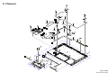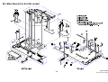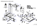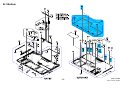
1
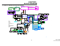
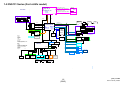
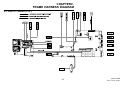
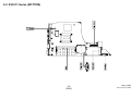
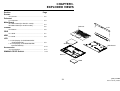
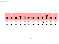
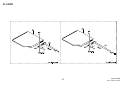
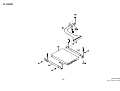
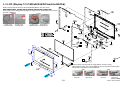
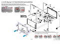
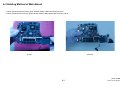
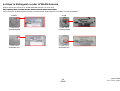
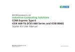
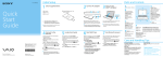
SVS131 Series
SERVICE MANUAL
Ver.1-2012I
Revision History
e
d
i
f
n
o
C
y
n
o
S
9-890-926-01
l
a
i
t
n
Design and specifications are subject to change
without notice.
PERSONAL COMPUTER
Service and Inspection Precautions
Sony, VAIO and CLIE are trademarks or regisSony
regis
teredtrademarks of Sony. Microsoft, Windows,
Windows Media, Outlook, Bookshelf and other
Microsoft products are trademarks or registered
trademarks of Microsoft Corporation in the
United States and other countries. The word
Bluetooth and the Bluetooth logo are trademarks
off Bluetooth
Bl t th SIG,
SIG Inc.
I
AMD the
AMD,
th AMD logo,
l
other
th
AMD product names and combinations thereof
are trademarks of Advanced Micro Devices, Inc.
Intel Inside logo, Pentium, Celeron and Core are
trademarks or registered trademarks of Intel Corporation. Transmeta, the Transmeta logo, Crusoe
Processor, the Crusoe logo and combinations
th
thereof
f are trademarks
t d
k off Transmeta
T
t Corporation
C
ti
in the USA and other countries. Graffi ti, HotSync, PalmModem, and Palm OS are registered
trademarks, and the Hotsync logo and Palm are
trademarks of Palm, Inc. or its subsidiaries. (M)
and Motrola are trademarks of Motrora, Inc. Other
Motrola products and services with (R) mark like
Dragomball are the trademarks of Motrola, Inc.
All other names of systems, products and services
in this manual are trademarks or registered tradeMarks of their respective owners. In this manual,
the (TM) or (R) mark are not specified.
Caution Markings for Lithium/Ion Battery - The
following or similar texts shall be provided on
battery pack of equipment or in both the operating
and the service instructions.
1. Obey precautionary markings and
Instructions
CAUTION: Danger of explosion if battery is
incorrectly replaced. Replace only with the same
or equivalent
i l t type
t
recommended
d d by
b the
th manufacturer. Discard used batteries according to the
manufacturer’s instructions.
Labels and stamps on the cabinet, chassis, and
components identify areas requiring special precautions Be sure to observe these precautions,
cautions.
precautions
as well as all precautions listed in the operating
manual and other associated documents.
CAUTION: The battery pack used in this device
may present a fi re or chemical burn hazard if mistreated. Do not disassemble, heat above 60̓C
(140̓F) or incinerate.
i i
t Dispose
Di
off used
d battery
b tt
promptly. Keep away from children.
2. Use designated parts only
The set’s components possess important safety
characteristics,
h
t i ti
such
h as noncombustibility
b tibilit and
d
the ability to tolerate large voltages. Be sure that
replacement parts possess the same safety characteristics as the originals. Also remember that the
Μ mark, which appears in circuit diagrams and
parts lists, denotes components that have particularly important safety functions; be extra sure to
use only
l th
the d
designated
i
t d components.
t
CAUTION: Changing the back up battery.
• Overcharging, short circuiting, reverse charging, multilation or incineration of the cells must
be avoided to prevent one or more of the following occurrences; release of toxic materials,
release of hydrogen and/or oxygen gas, rise in
surface temperature.
• If a cell has leaked or vented, it should be
replaced immediately while avoiding to touch
it without any protection.
3. Always follow the original design
when mounting parts and routing
Wires
The original layout includes various safety feafea
tures, such as inclusion of insulating materials
(tubes and tape) and the mounting of parts above
the printer board. In addition, internal wiring has
been routed and clamped so as to keep it away
from hot or high-voltage parts. When mounting
parts or routing wires, therefore, be sure to duPli t th
Plicate
the original
i i l llayout.
t
4. Inspect after completing service
After servicing, inspect to make sure that all
screws, components, and wiring have been
returned to their original condition. Also check
the area around the repair
p location to ensure that
repair work has caused no damage, and confirm
safety.
5. When replacing chip
components...
Never reuse components. Also remember that
the negative side of tantalum capacitors is easily
damaged by heat.
6. When handling flexible print
boards...
• The temperature of the soldering-iron tip
should be about 270̓C.
• Do not apply the tip more than three times to
the same pattern.
• Handle patterns with care; never apply force.
Caution: Remember that hard disk drives are
easily damaged by vibration. Always handle
with care. The components identified by mark contain
confidential information.
Strictly follow the instructions whenever the
components repaired and/or replaced.
2
[Sony Confidential]
SVS131 Series (9-890-926-XX)
TABLE OF CON
NTENTS
Section
Title
Page
Section
CHAPTER1. BLOCK DIAGRAM
1-1. SVS131 Series (For Ext-Gfx model)…………….…… 1-1
1 2 SVS131 Series
1-2.
S i (For
(F Int-Gfx
I t Gf model)…………..………
d l)
1-2
(to 1-2)
CHAPTER2. FRAME HARNESS DIAGRAM
2-1. SVS131 Series (TOP)…………...…………….……… 2-1
)
2-2. SVS131 Series ((BOTTOM)……………………..………
2-2
2
2
(to 2-2)
CHAPTER3. EXPLODED VIEWS
Screws
S-1. Screws………………………………………….…….........
3-2
Palmrest
P-1. Palmrest………………………………………….......…..…
3-3
Main Board
M-1. Main Board (For Ext-Gfx model)………………………….
3-4
M-2. Main Board (For Int-Gfx model)…………………… 3-5
Bottom
B-1. Bottom………………………………………………..………
3-6
ODD
D-1. ODD…………………………………………………………
3-7
HDD
H-1. HDD……………………………………………………………
3-8
LCD
L-1. LCD (Display:13.3/1600x900/LED/
ClearLikeAG/Flat).................................................. 3-9
L 2 LCD (Di
L-2.
(Display:13.3/1366x768/LED/
l 13 3/1366 68/LED/
ClearLikeAG/Flat)………….....................................3-10
Accessories
A-1. Accessories…………………………..……………… 3-11
WWAN/LCD DIP Switch……………………………………………
3-12
3
12
(to 3-12)
Title
Page
CHAPTER4.OTHERS
4-1. Note for WWAN Board Replacement ……………….…… 4-1
4 2 Note
4-2.
N t ffor WIMAX B
Board
dR
Replacement
l
t ……….…………… 4-2
42
4-3. Holding Method of Mother Board…………….…………… 4-3
4-4. How to distinguish vendor of WLAN Antenna …………… 4-4
(to 4-4)
x History of the changes is shown as the “Revision
History” at the end of this data.
3
[Sony Confidential]
SVS131 Series (9-890-926-XX)
CHA
APTER1.
BLOCK DIA
AGRAM
1-1.SVS131 Series (For Ext-Gfx model)
DDR3 VRAM
NVIDIA
N13P_LP
1GB/2GB
(1Gbx8/2Gbx8)
64Mx16bitx8/128Mx16bx8
Sandy Bridge: DDR3 1333 MT/S
IVY Bridge: DDR3L 1333MT/S /DDR3 1600MT/S
Intel Processor
IVY Bridge SV_DC
or
Sandy Bridge SV_DC
DGPU
PCIE X8
Channel B
SO-DIMM 0
204 pin
OUTPUTS
BT+
Page 19
Sandy Bridge: DDR3 1333 MT/S
IVY Bridge: DDR3L 1333MT/S /DDR3 1600MT/S
BGA-1023
(TDP 35W)
Channel A
4GB/2GB On Board
Page 20~24
OUTPUTS
Page 3~9
Page 34~39
Page 25~33
+3VALW/
+5VALW
Port Replicator
MCU
CRT
DP Converter
FDI
DMI X4
PECI
HDMI
OUTPUTS
DP Converter
+1.8VRUN
GbE Controller
TMDS
HDMI
PCIE(Gen 2)
Page 43
LVDS 13.3''
1600 X 900
1366 X 768
Page 41
USB3.0 bus port 1&3
HM77 or HM76
TDP 4W
989 Ball FCBGA
25 mm X 25 mm
Page 40
DDPD
(USB2.0 x 14)
(USB3.0 x 4)
(PCIE x 8)
(SATA x 6)
SATA
0(6G)
1(6G)
Page 10~18
Int. Speaker
On MS/SD
Audio Codec
w/ HWEQ
HDA
LPC
SPI
Int. DMIC
OUTPUTS
+1.5VSUS
SSD
Gigabit LAN HUB
RTL8365MB
none RAID
(SATA0)
RAID (HM77)
(SATA0,1)
/2con RAID (HM77)
(SATA0,1)
Transformer*2
USB 2.0 HUB IC
GL852G
RJ45*2
OUTPUTS
USB to SATA
5
Headphone
jack stereo
0&2
Page 50
4(1.5G)
On Speed DB
USB 2.0 *3
USB 3.0 *2 Page 55
2
SATA ODD
H=9.5mm
Page 51
1
SLB 9635 TT 1.2A
Debug Port
Page 63
SMB01
Page 46
8
SMB00
SD Card
OUTPUTS
On MS_SD DB
OUTPUTS
DCBATOUT
BQ24725Page 66
13
BluetoothPage 60
11
WWAN
PWM
Charge IC
TPS2540RTE
Page 57~59
OUTPUTS
+VHCORE
SIM Card
DB
USB 2.0*1 Page 54
OUTPUTS
+GFXCORE
On MS_SD DB
G-Sensor
Page 61
Touch PAD
+1_05V_PCH
Camera Page 52
BATT CONN
1
LIS331DLHTR
DCBATOUT
on LED DB
10
SMB01
PS2
MS Card
REALTEK
RTS5209
FingerPrint
Battery ID
R5G05000N753NFPage 67
Page 44~45
OUTPUTS
Port Replicator
Memory Card
controller
WLAN/WiMAX
Intel kilmer peak 2*2
Page 56
WLAN
9
TPM DB
EC SMSC
MEC1621
W/ Back
light keyboard
0.75VRUN
SATA
+5VALW
LPC
LEDs
-Power
-Charge
-Performance STAMINA/SPEED
-Keyboard num/caps/scr lk
-HDD/Optical Disc Drive
-Wireless
-Camera
-MS/SD
Transformer
SSD 2con RAID module has
2 controllers on a moudle
On LED DB
Switchs
-Performance STAMINA/SPEED
-Wireless ON/OFF
Page 49
(SATA0)
System BIOS
32M bit X 1
On MS_SD DB
Button
-Power
-ASSIST
-Web(WiDi)
-VAIO
-ODD Eject
RJ45
Page 49
Transformer
HDD
REALTEK
ALC275
Transformer
Page 49
USB 2.0
CRT
CRT
3
Page 48
PCH (PPT)
Panther Point-M
LVDS
SW
Page 49
REALTEK
RTL8111F
Lid Switch
LEDs
FAN
Thermal Sensor
G709T1UF
(H/W shutdown)
For CPU Page 62
Switchs
DPWM
on LED DB
Thermal Sensor
G709T1UF
(H/W shutdown)
For GPU Page 62
Page 47
Light Sensor
BH1600FVC-TR
switch DB on Speed DB
Thermal Sensor
G709T1Uf
For Ambient Page 62
Docking
Block
HDMI
RGB
DDPD
USB 2.0
USB 2.0
1--1
[Sony Confidential]
LAN HUB
Giga LAN 2
SVS131 Series (9-890-926-XX)
1-2.SVS131 Series (For Int-Gfx model)
DDR3 VRAM
NVIDIA
N13P_LP
1GB/2GB
(1Gbx8/2Gbx8)
64Mx16bitx8/128Mx16bx8
Sandy Bridge: DDR3 1333 MT/S
IVY Bridge: DDR3L 1333MT/S /DDR3 1600MT/S
Intel Processor
IVY Bridge SV_DC
or
Sandy Bridge SV_DC
DGPU
Channel B
SO-DIMM 0
204 pin
OUTPUTS
BT+
Page 19
Sandy Bridge: DDR3 1333 MT/S
IVY Bridge: DDR3L 1333MT/S /DDR3 1600MT/S
BGA-1023
(TDP 35W)
Channel A
4GB/2GB On Board
Page 20~24
OUTPUTS
Page 3~9
Page 34~39
Page 25~33
+3VALW/
+5VALW
Port Replicator
MCU
CRT
DP Converter
FDI
DMI X4
PECI
HDMI
OUTPUTS
DP Converter
+1.8VRUN
GbE Controller
PCIE(Gen 2)
TMDS
HDMI
Page 43
LVDS 13.3''
1600 X 900
1366 X 768
Page 41
USB3.0 bus port 1&3
HM76
TDP 4W
989 Ball FCBGA
25 mm X 25 mm
Page 40
DDPD
(USB2.0 x 14)
(USB3.0 x 4)
(PCIE x 8)
(SATA x 6)
SATA
0(6G)
1(6G)
Page 10~18
Int. Speaker
On MS/SD
Audio Codec
w/ HWEQ
HDA
LPC
SPI
Int. DMIC
OUTPUTS
+1.5VSUS
SSD
Gigabit LAN HUB
RTL8365MB
none RAID
(SATA0)
RAID (HM77)
(SATA0,1)
/2con RAID (HM77)
(SATA0,1)
Transformer*2
USB 2.0 HUB IC
GL852G
RJ45*2
OUTPUTS
USB to SATA
5
Headphone
jack stereo
0&2
Page 50
4(1.5G)
On Speed DB
USB 2.0 *3
USB 3.0 *2 Page 55
2
SATA ODD
H=9.5mm
Page 51
1
SLB 9635 TT 1.2A
Debug Port
Page 63
SMB01
Page 46
8
SMB00
SD Card
OUTPUTS
On MS_SD DB
OUTPUTS
DCBATOUT
BQ24725Page 66
13
BluetoothPage 60
WWAN
PWM
Charge IC
TPS2540RTE
Page 57~59
OUTPUTS
+VHCORE
SIM Card
DB
USB 2.0*1 Page 54
OUTPUTS
+GFXCORE
On MS_SD DB
Page 61
Touch PAD
W/ Back
light keyboard
+1_05V_PCH
Camera Page 52
BATT CONN
1
G-Sensor
DCBATOUT
on LED DB
10
11
PS2
MS Card
REALTEK
RTS5209
FingerPrint
Battery ID
R5G05000N753NFPage 67
Page 44~45
OUTPUTS
Port Replicator
Memory Card
controller
WLAN/WiMAX
Intel kilmer peak 2*2
Page 56
WLAN
9
TPM DB
EC SMSC
MEC1621
SMB01
LIS331DLHTR
0.75VRUN
SATA
+5VALW
LPC
LEDs
-Power
-Charge
-Performance STAMINA/SPEED
-Keyboard num/caps/scr lk
-HDD/Optical Disc Drive
-Wireless
-Camera
-MS/SD
Transformer
SSD 2con RAID module has
2 controllers on a moudle
On LED DB
Switchs
-Performance STAMINA/SPEED
-Wireless ON/OFF
Page 49
(SATA0)
System BIOS
32M bit X 1
On MS_SD DB
Button
-Power
-ASSIST
-Web(WiDi)
-VAIO
-ODD Eject
RJ45
Page 49
Transformer
HDD
REALTEK
ALC275
Transformer
Page 49
USB 2.0
CRT
CRT
3
Page 48
PCH (PPT)
Panther Point-M
LVDS
SW
Page 49
REALTEK
RTL8111F
Lid Switch
LEDs
FAN
on LED DB
Thermal Sensor
G709T1UF
(H/W shutdown)
For CPU Page 62
Switchs
DPWM
Thermal Sensor
G709T1UF
(H/W shutdown)
Page 62
F
Page 47
Light Sensor
BH1600FVC-TR
switch DB on Speed DB
Thermal Sensor
G709T1Uf
For Ambient Page 62
Docking
Block
HDMI
RGB
DDPD
USB 2.0
USB 2.0
LAN HUB
Giga LAN 2
Port Replicator
1--2
(EN
ND)
[Sony Confidential]
SVS131 Series (9-890-926-XX)
CHA
APTER2.
FRAME HARNESS DIA
AGRAM
2-1.SVS131 Series (TOP)
2--1
[Sony Confidential]
SVS131 Series (9-890-926-XX)
2-2. SVS131 Series (BOTTOM)
2--2
(EN
ND)
[Sony Confidential]
SVS131 Series (9-890-926-XX)
CHA
APTER3.
EXPLODED
D VIEWS
Section
Screws
Page
S-1.Screws…………………………………………….… 3-2
Palmrest
P-1.Palmrest………………………………………….… 3-3
Main Board
M-1.Main Board (For Ext-Gfx model)…….………………
3-4
M-2.Main Board (For Int-Gfx model)….….………….. 3-5
Palmrest
Bottom
LCD
B-1.Bottom………………………………………………. 3-6
ODD
D-1.ODD……………………………………………….… 3-7
HDD
H-1.HDD………………………………………………….
H
1.HDD…………………………………………………. 3
3-8
8
LCD
L-1.LCD (Display:13.3/1600x900/LED/
ClearLikeAG/Flat)………………………………….. 3-9
L-2.LCD (Display:13.3/1366X768/LED/
ClearLikeAG/Flat)………………………………….. 3-10
ODD
Main Board
Accessories
A-1.Accessories……………………………….……….. 3-11
WWAN/LCD DIP Switch………………………………………
3-12
Botto
om
HDD
3--1
[Sony Confidential]
SVS131 Series (9-890-926-XX)
S-1.Screws
3--2
[Sony Confidential]
SVS131 Series (9-890-926-XX)
P-1.Palmrest
3--3
[Sony Confidential]
SVS131 Series (9-890-926-XX)
M-1.Main Board (For Ext-Gfx model)
3--4
[Sony Confidential]
SVS131 Series (9-890-926-XX)
M-2.Main Board (For Int-Gfx model)
3--5
[Sony Confidential]
SVS131 Series (9-890-926-XX)
B-1.Bottom
3--6
[Sony Confidential]
SVS131 Series (9-890-926-XX)
D-1.ODD
3--7
[Sony Confidential]
SVS131 Series (9-890-926-XX)
H-1.HDD
3--8
[Sony Confidential]
SVS131 Series (9-890-926-XX)
L-1.LCD (Display:13.3/1600x900/LED/ClearLikeAG/Fla
at)
SVS131 Series have two kinds of WLAN ANTENNA (Ref.No.1011 and 1012).
When replacing either
either, The Main and Aux Antenna must use same vendor's
vendor s parts
parts.
Part’s vendor can be distinguished by shape of red boxed area. Wide shape one is ACON’s,
the other is NWING’s.
NWING
ACON
A-1881-575-A
ANTENNA MAIN
A-1881-576-A
ANTENNA AUX
A-1881-573-A
A-1881-574-A
ANTENNA MAIN ANTENNA AUX
SVS131 Series have two kinds of Hinge (Ref.No.1015
(Ref No 1015 and 1016)
1016).
When replacing either, The Left and Right Hinge must use same vendor's parts.
Vendor name is inscribed on red circled area.
Jarlly
SZS
4-428-282-01
Left Hinge
3--9
4-428-283-01
Right Hinge
4-428-282-11
Left Hinge
4-428-283-11
Right Hinge
[Sony Confidential]
SVS131 Series (9-890-926-XX)
L-2.LCD (Display:13.3/1366x768/LED/ClearLikeAG/Fla
at)
SVS131 Series have two kinds of WLAN ANTENNA (Ref.No.1011 and 1012).
When replacing either
either, The Main and Aux Antenna must use same vendor's
vendor s parts
parts.
Part’s vendor can be distinguished by shape of red boxed area. Wide shape one is ACON’s,
the other is NWING’s.
NWING
ACON
A-1881-575-A
ANTENNA MAIN
A-1881-576-A
ANTENNA AUX
A-1881-573-A
A-1881-574-A
ANTENNA MAIN ANTENNA AUX
SVS131 Series have three kinds of Hinge (Ref.No.1115 and 1116).
When replacing either, The Left and Right Hinge must use same vendor's parts.
Vendor name is inscribed on red circled area.
SZS
Jarlly
LH
4-428-652-01
Left Hinge
3-10
4-428-653-01
Right Hinge
4-428-652-11 4-428-653-11
Left Hinge
Right Hinge
4-428-652-21 4-428-653-21
Left Hinge
Right Hinge
[Sony Confidential]
SVS131 Series (9-890-926-XX)
A-1.Accessories
2005
Power Cord
2005
Power Cord
2006
AC Adapter
(for Stick Type Adapter)
2007
Battery Pack
2006
AC Adapter
(Stick Type)
2011
Carrying Pouch
2012
Cable Clip
2014
Extended Battery
2015
Battery Adapter
3-11
[Sony Confidential]
SVS131 Series (9-890-926-XX)
WWAN/LCD DIP Switch
WWAN/LCD DIP Switch Location
There are four DIP Switches.
1. The first one is used for WWAN Card, please set them as below.
With WWAN SKUS
Without WWAN SKUS
2. The second and third are used for LCD DIP Switch setting.
g
13.3/1600x900/LED/ClearLikeAG/Flat/CMI (A-1890-097-A)
13.3/1366X768/LED/CLEARLIKEAG/FLAT/AUO (A
(A-1890-100-A/A-1898-069-A)
1890 100 A/A 1898 069 A)
13.3/1366X768/LED/CLEARLIKEAG/FLAT/CMI ((A-1890-098-A/A-1890-099-A))
3.The fourth one is used for Intel Anti-Theft setting.
When replacing Main Board
Board, not to change the setting on removed Main Board
Board.
With Intel Anti-Theft
Without Intel Anti-Theft
3-1
12
(EN
ND)
[Sony Confidential]
SVS131 Series (9-890-926-XX)
CHA
APTER4.
OTHERS
4-1.Note for WWAN Board Replacement
When replacing the WWAN Board (Ref.309 A-1920-698-A/ A-1920-699
9-A), change the barcode label on the bottom.
1. Peel off the barcode label which is attached to the bottom. (Refer to the figure below.)
Ref.No.309
A-1920-698-A GOBI3000 US-EU-AP MINICARD(F)(S) [EU/Generic/HSPA/MC/Huawei/GOBI3000]
A-1920-699-A LTE EU WWAN MINI CARD(F)(S) [EU/RU(SIM)/Yota/LTE_HSPA/900,1800/Band
1,8/Band 7,20/MC/Sierra]
WWAN X X X X X X X X X X X X
WWAN:XXXXXXXXXXXX
2. Attach the barcode label which is included with the WWAN Board to
t the position where you peeled off the label in the step 1.
4--1
[Sony Confidential]
SVS131 Series (9-890-926-XX)
4-2.Note for WIMAX Board Replacement
When replacing the WIMAX Board (Ref.305 A-1891-489-A), change the
e barcode label on the bottom.
1. Peel off the barcode label which is attached to the bottom. (Refer to the figure below.)
Re
ef.No.305
A--1891-489-A
CARD, WLAN/WIMAX COMBO(B)(S) [bgn/Intel/KsP_1x2/WiMAX] ASSY
WIMAX:XXXXXXXXXXXX
2 Attach the barcode label which is included with the WIMAX Board to the position where you peeled off the label in the step 1
2.
1.
4--2
[Sony Confidential]
SVS131 Series (9-890-926-XX)
4-3 Holding Method of Main Board
1. When operating with both hands, gently hold the middle of Main Board edge as show
w.
2. When operating with one-hand, gently hold the middle of Main Board edge and keep vertical.
(Level)
(Vertical)
4--3
[Sony Confidential]
SVS131 Series (9-890-926-XX)
4-4 How to distinguish vendor of WLAN Antenna
SVS131 Series have two kinds of WLAN ANTENNA (Ref.No.1011 and 1012).
When replacing either
either, The Main and Aux Antenna must use same vendor's parts
parts.
Part’s vendor can be distinguished by shape of red boxed area. Wide shape one is ACON’s
s, the other is NWING’s.
NWING
ACON
A-1881-575-A
ANTENNA MAIN
A-188
A
188
81 573 A
81-573-A
ANTEN
NNA MAIN
A-1881-576-A
ANTENNA AUX
A-188
81-574-A
ANTENNA AUX
4--4
(EN
ND)
[Sony Confidential]
SVS131 Series (9-890-926-XX)
SVS131 Series
This manual and the constituent data may not be replicated, copied nor
reprinted in whole or in part without prior written authorization of Sony
Corporation
9-890-926-01
Sony Corporation
24
English
2012IF00-1
© 2012 Sony Corporation
Published by Sony Corporation VAIO & Mobile Business Group
CS & Quality Div. VAIO Global CS Dept.
Revision History
Suffix
Ver.
Date
-01
Ver 1
Ver.1
2012 09 19
2012.09.19
Contents
QM No.
First Edition
<Remarks>
556
[Sony Confidential]
SVS131 Series (9-890-926-XX)