1
'DBktroniK
®
COMMITTED TO EXCELLENCE
PLEASE CHECK FOR CHANGE INFORMATION
AT THE REAR OF THIS MANUAL.
2445/2465
OPTION 05
TV OPTION
OPERATORS
INSTRUCTION
Tektronix, Inc.
P.O. Box 500
Beaverton, Oregon
070-4629-00
Product Group 38
97077
MANUAL
Serial Number
First Printing OCT 1983
Revised MAY 1984
Copyright '^' 1983 Tektronix, Inc. All rights reserved.
Contents of this publication may not be reproduced in any
form without the written permission of Tektronix, Inc.
Products of Tektronix, Inc. and its subsidiaries are covered
by U.S, and foreign patents and/or pending patents.
TEKTRONIX, TEK, SCOPE-MOBILE, and
^ ^
a""®
registered trademarks of Tektronix, Inc. TELEQUIPMENT
is a registered trademark of Tektronix U.K. Limited.
Printed in U.S.A. Specification and price change privileges
are reserved.
INSTRUMENT SERIAL NUMBERS
Each instrument has a serial numtjer on a panel insert, tag,
or stamped on the chassis. The first numt)er or letter
designates the country of manufacture. The last five digits
of the serial number are assigned sequentially and are
unique to each instrument. Those manufactured in the
United States have six unique digits. The country of
manufacture is identified as follows:
BOOOOOO
Tektronix, Inc., Beaverton, Oregon, USA
100000
Tektronix Guernsey, Ltd., Channel Islands
200000
Tektronix United Kingdom, Ltd., London
300000
Sony/Tektronix, Japan
700000
Tektronix Holland, NV, Heerenveen,
The Netheriands
2445/2465 Option 05 Operators
TABLE OF CONTENTS
Page
Page
LIST OF ILLUSTRATIONS
LIST OF TABLES
OPERATORS SAFETY SUMMARY
Section 1 SPECIFICATION
INTRODUCTION
STANDARD ACCESSORIES
PERFORMANCE CONDITIONS
Section 2 CONTROLS AND INDICATORS
FRONT-PANEL CONTROLS
READOUT DISPLAYS
Section 3 PREPARATION FOR USE
POWER-UP SEQUENCE
Kernel Test
Successful Power-Up Sequencing . .
POWER-DOWN SEQUENCE
TV PROTOCOL AND LINE-NUMBERING
FORMAT SELECTION
ii
ii
iii
1-1
1-1
1-1
2-1
2-3
Section 4 OPERATING CONSIDERATIONS
FRONT-PANEL CONTROL AND
SETUP CONSIDERATIONS
TV Clamp
A-FLD LINE # Control
Slope Selection
Display Considerations
Oscilloscope Dc Balance Routine . . .
Front Panel Update
CH 2 SIGNAL OUT Connector
IDENTIFYING FIELDS, FRAMES, AND
LINES IN 525/60 AND 625/50 TV
SYSTEMS
NTSC (CCIR System M)
CCIR System B and Similar 625/50
Systems (including PAL)
GPIB CONTROLLABLE FUNCTIONS . .
3-1
3-1
3-1
3-1
Section 5 BASIC APPLICATIONS
Initial Setup
Signal Input Coupling
Time Interval Measurements
Voltage and IRE Measurements . . . .
3-1
CHANGE INFORMATION
4-1
4-1
4-1
4-1
4-1
4-2
4-2
4-2
4-2
4-2
4-2
4-3
5-1
5-1
5-2
5-2
2445/2465 Option 05 Operators
LIST OF ILLUSTRATIONS
Figure
Page
The 2445 Option 05 (TV) Oscilloscope
iv
The 2465 Option 05 (TV) Oscilloscope
iv
2-1
TV Option front-panel controls
2-2
5-1
Appearance of video signal with CH 2 Input Coupling switch positions
5-1
LIST OF TABLES
Table
Page
1-1
1 -2
Option 05 Electrical Characteristics
Option 05 Mechanical Characteristics
1-2
1-3
4-1
GPIB Command Set for the TV Option
4-4
2445/2465 Option 05 Operators
OPERATORS SAFETY SUMMARY
The general safety summary in this part of the summary is for both operating and servicing personnel. Specific warnings and
cautions will be found throughout the manual where they apply and do not appear in this summary.
Terms in This Manual
Grounding the Product
CAUTION Statements identify conditions or practices that
could result in damage to the equipment or other property.
This product is grounded through the grounding conductor
of the power cord. To avoid electrical shock, plug the power
cord into a properly wired receptacle t)efore connecting to
the product input or output terminals. A protective ground
connection by way of the grounding conductor in the power
cord is essential for safe operation.
WARNING statements identify conditions or practices that
could result in personal injury or loss of life.
Terms as Marked on Equipment
Danger Arising From Loss of Ground
CAUTION indicates a personal injury hazard not immediately accessible as one reads the markings, or a hazard to
property, including the equipment itself.
Upon loss of the protective-ground connection, all accessible conductive parts (including knobs and controls that may
appear to be insulating) can render an electric shock.
DANGER indicates a personal injury hazard immediately accessible as one reads the marking.
Use the Proper Power Cord
Use only the power cord and connector specified for your
product.
Symbols as Marked on Equipment
This symtx)! indicates where applicable
cautionary or other information is to be found.
Protective ground (earth) terminal.
A
Use only a power cord that is in good condition.
Use the Proper Fuse
To avoid fire hazard, use only a fuse of the correct type,
voltage rating and current rating as specified in the parts list
for your product.
ATTENTION — Refer to manual.
Power Source
This product is intended to operate from a power source
that does not apply more than 250 volts rms between the
supply conductors or between either supply conductor and
ground, A protective ground connection by way of the
grounding conductor in the power cord is essential for safe
operation.
Do Not Operate in Explosive Atmospheres
To avoid explosion, do not operate this product in an explosive atmosphere unless it has t}een specifically certified for
such operation.
Do Not Remove Covers or Panels
To avoid personal injury, do not remove the product covers
or panels. Do not operate product without the covers and
panels properiy installed.
Ill
2445/2465 Option 05 Operators
The 2445 Option 05 (TV) Oscilloscope.
The 2465 Option 05 (TV) Oscilloscope.
IV
Section 1
2445/2465 Option 05 Operators
SPECIFICATION
INTRODUCTION
STANDARD ACCESSORIES
The TEKTRONIX 2445 and 2465 Oscilloscopes with Option 05 (TV Option) have additional hardware and software
features to simplify triggering and viewing of television signals. The option adds TV (back-porch) clamp circuitry to the
Channel 2 input and TV trigger coupling modes are provided, allowing a user to select either horizontal or vertical
sync pulses to obtain horizontal-line-sync or field-sync pulse
triggering. This option permits the user to trigger on a specific line number within a TV field and provides sync polarity
switching for either sync-negative or sync-positive composite video signals.
In addition to the standard accessories listed in the basic
oscilloscope manuals, the following TV Option accessories
are provided:
NOTE
Quantity
Description
Part Number
1
2445/2465 Option 05,
TV Option, Operators Manual
070-4629-00
1
2445/2465 Option 05,
TV Option, Service Manual
070-4630-00
1
CCIR Graticule
378-0199-01
1
NTSC Graticule
378-0199-02
1
Polarized Viewing Hood
016-0180-00
Composite video is the picture waveform complete
with vertical and horizontal blanking and sync. Composite sync is combined vertical and horizontal sync
as a single waveform, but without video (picture)
waveforms.
Both system-M and nonsystem-M protocols are available, providing compatibility with most television signal linenumbering protocols. Stable video rejection and sync
separation is obtained from sync-positive or sync-negative,
interlaced or non-interlaced scan, composite video signals
having 525 to 1280 horizontal lines per frame and 50- or
60-Hz field rates.
PERFORMANCE CONDITIONS
Except as noted in Tables 1 -1 and 1 -2 of this manual, the
electrical, environmental, and mechanical characteristics of
TV Option instruments are identical to those specified for
basic instruments in the respective 2445 and 2465 Oscilloscope manuals.
1-1
Specification
2445/2465 Option 05 Operators
Table 1-1
Option 05 Electrical Characteristics
Performance Requirements
Characteristics
VERTICAL DEFLECTION SYSTEM—CHANNEL 1 AND CHANNEL 2
Frequency Response
For VOLTS/DIV switch settings between 5 mV and 0.2 V/div with VAR
control in calibrated detent. Five-division, 50 kHz reference signal from a
50 fi system. With external 50 fi termination on 1 Mfi input.
Full Bandwidth
50 kHz to 5 MHz
> 5 MHz to 10 MHz
> 1 0 MHz to 30 MHz
Within ± 1 % .
Within 4-1%, - 2 % .
Within 4-2%, - 3 % .
Bandwidth Limit
50 kHz to 5 MHz
Square Wave Flatness
Within 4-1%, - 4 % .
With fast-rise step (rise t i m e ^ l ns), 1 Mfi dc input coupling, an external
50 fi termination, and VAR VOLTS/DIV control in calibrated detent.
Exclude the first 50 ns following the step transition. For signals with rise
times =s10ns, add 2% p-p between 155 ns and 165 ns after step
transition.
Field Rate
5mV/divto lOmV/div
1.5% p-p at 60 Hz with input signal of 0.1 V.
20 mV/div
1 % p-p at 60 Hz with input signal of 0.1 V.
50 mV/div
1 % p-p at 60 Hz with input signal of 1.0 V.
Line Rate
5mV/div to lOmV/div
1.5% p-p at 15 kHz with input signal of 0.1 V.
20 mV/div
1 % p-p at 15 kHz with input signal of 0.1 V.
50 mV/div
1 % p-p at 15 kHz with input signal of 1.0 V.
TV (Back-Porch) Clamp (CH 2 only)
60 Hz Attenuation
Back-Porch Reference
1-2
For VOLTS/DIV switch settings between 5 mV and 0.2 V with VAR
control in calibrated detent. Six-division reference signal.
^ 1 8 dB.
Within 1.0 division of ground reference.
REV MAY 1984
Specification
2445/2465 Option 05 Operators
Table 1-1 (cont)
Characteristics
Performance Requirements
TRIGGERING
Sync Separation
Stable video rejection and sync separation from sync-positive or syncnegative composite video, 525 to 1280 lines, 50 Hz or 60 Hz, interiaced
or noninterlaced systems.
Trigger Modes
Main Sweep
All lines:
Field 1, selected line (1 to n);
Field 2, selected line (1 to n);
Alt fields, selected line (1 to n);
where n is equal to or less than the number of lines in the frame and less
than or equal to 1280.
Delayed by time.
Delayed Sweep
Input Signal Amplitude for Stable Triggering
Minimum for peak signal amplitude within 18 divisions of input ground
reference.
Channel 1 or Channel 2
1 division.
0,3 division.
Composite Video
Composite Sync
Minimum for peak signal amplitude within 9 divisions of input ground
reference.
Channel 3 or Channel 4
0.5 division.
0.25 division.
Composite Video
Composite Sync
Table 1-2
Option 05 Mechanical Characteristics
Description
Characteristics
Weight
With Power Cord, Cover, Pouch, Probes,
Operators Manual, and Options
Domestic Shipping Weight
«12.0 kg (26.4 1b).
«17.6kg(38.8 1b).
1-3
Section 2
2445/2465 Option 05 Operators
CONTROLS AND INDICATORS
FRONT-PANEL CONTROLS
the "Operating Considerations" section of this manual for further information about using this control.
Certain front-panel controls on the oscilloscope have
dual modes of operation when the TV Option is installed.
When the TV Option is enabled, the controls have the functions as described below. When the TV Option is not enabled, the controls have the functions described in the
oscilloscope Operators manual and in other option Operators manuals if other options are installed.
When the line number setting reaches the maximum
number of lines in a field and either FLD 1 or FLD 2
coupling is selected, additional clockwise turning of
the control changes the line number to the t)eginning
of the following field. If alternate FLD 1-FLD 2 coupling (ALT) is selected, further rotation of the control
past the maximum number will only reset the count
to1.
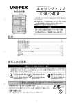
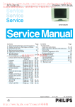
See Figure 2-1 for the location of the TV Option frontpanel controls.
(in
When the line numt)er setting reaches 1 and either
FLD 1 or FLD 2 coupling is selected, counterclockwise rotation of the control will move the line number
to the maximum line number of the previous field. If
ALT coupling is selected, the line number will move
to the maximum line number common to txjth fields.
CH 2 Input Coupling Switch—Selects or deselects
the TV (back-porch) clamp function.
UPiTV CLAMP—Activates the TV (back-porch)
clamp when the switch is pushed up from the 1 Mfi
AC position. The AC indicator LED will remain on
and the message "TVC will appear on the top line
of the crt. The clamp sets the television signal
back-porch amplitude to a constant dc level and
eliminates vertical drift, hum, and tilt in the display,
A stable display is provided despite changes in signal amplitude and average luminance levels. The
TV (back-porch) clamp can be enabled even if TV
trigger is deselected,
See the "Line Numtjer Format Selection" discussion
in the "Preparation for Use" section of this manual
to choose the desired line number format. See the
example t»elow for operation with a 525-line interlaced scan signal.
Format 1 . . I 1 2 , . 263 ll 2 . . . 2621
Format 2 . , I 1 2 .. 263 1264 . . . 5251
AC—Deactivates the TV (back-porch) clamp when
the switch is pushed down once from the UP:TV
CLAMP position. The AC indicator LED will remain
on and the message "TVC will be removed from
the top of the crt. The television signal's level will
then be set by the average signal level and vary
with that average level.
(32)
A-FLD LINE # Control—Selects a specific line
number within the field for triggering the oscilloscope when the TV Option is enabled and the Trigger COUPLING switch is set to FLD 1, FLD 2, or
alternate FLD 1 -FLD 2 mode. Possible line numt)ers
range from 1 to the maximum number of lines per
frame in the television signal t>eing viewed. Rotating
the control clockwise increases the line numtier; rotating it counterclockwise decreases the line number. See the "A-FLD LINE # Control" discussion in
Field
I
FLD LINE #
Control Rotation
®
1
I
CCW-
2
I
-^CW
TRIGGER
COUPLING
Switch
and
Indicators—Selects and indicates one of four additional choices for trigger coupling. They are: FLD 1
(field 1), FLD 2 (field 2), ALT (altemate field 1-field 2),
and LINES (horizontal TV-line sync triggering). The
crt readout will display the trigger coupling mode.
FLD 1—Sweep is triggered on the first field of the
input TV signal and the FLD 1 LED is illuminated,
NORM trigger mode is automatically selected.
2-1
Controls and Indicators
2445/2465 Option 05 Operators
3 VERTICAL C
{ ) POSITION
^POSITION
•a
"
MODE
CHI
n
ADO J
D
CH2-^
n
INVERT-
D
,
CH3
CH«
a
D
20MN;
CHOP BW LIMIT
a
D
aUT:ALT
4629-03
Figure 2-1. TV Option front-panel controls.
2-2
Controls and Indicators
2445/2465 Option 05 Operators
FLD 2—Sweep is triggered on the second field of
the input TV signal and the FLD 2 LED is illuminated. NORM trigger mode is automatically
selected,
ALT—Sweep is alternately triggered by the two
TV fields and both the FLD 1 and FLD 2 LEDs are
illuminated. NORM trigger mode is automatically
selected.
When CHOP Vertical Mode is selected, all of the
active channels are triggered alternately by field
1 and field 2 of the video signal. The two fields
will appear overlayed.
When ALT Vertical Mode is selected and more
than one channel is displayed, field 1 of the
video signal will trigger the first active channel
and field 2 will trigger the next active channel.
When more than two channels are displayed,
each additional channel will be triggered first by
field 1 and then by field 2 of the video trigger
signal, and its two fields will be overiayed.
LINES—Sweep will trigger when the holdoff time
has elapsed and a TV horizontal line-sync pulse is
encountered. The LINES LED is illuminated and
AUTO trigger mode is automatically selected.
READOUT DISPLAYS
In addition to the readout displays for oscilloscope operation shown in Sections 3 and 6 in the oscilloscope Operators manual, an instrument equipped with the TV Option
will display option status information when in any of the TV
modes. Also see the "Operating Considerations" section of
this manual for additional information.
The crt readout will display TV Trigger information when
the Trigger COUPLING switch is set to any of the TV trigger
modes (FLD 1, FLD 2, ALT, or LINES) or when the TV
(back-porch) clamp is active. The TV Option utilizes a display area of up to 12 characters that are normally located in
the right half of the top display line of the crt readout. If the
right half is not available, the TV Option information is displayed in the left half of the top line.
When field triggering is selected, the readout displays the
line number selected for triggering the oscilloscope. The line
number readout is followed by a delta (A) symtxDl if the FLD
LINE # control is controlling the line number selection. If the
A symbol is not present, the FLD LINE # control will not
change the line number selection. The crt readout displays
the message "TVC" whenever the TV (back-porch) clamp is
active.
2-3
Section 3
2445/2465 Option 05 Operators
PREPARATION FOR USE
This section of the manual contains information related
to the power-up of the main instrument containing the TV
Option. The power-up sequence of the oscilloscope is described, along with explanations of potential option-related
error messages that may occur if the instrument is not functioning properly. Also included is initial setup information for
the selection of the TV protocol and line number format
parameters.
POWER-UP SEQUENCE
Before turning on power to the instrument, read Section
2, "Preparation for Use," in the oscilloscope Operators manual and follow the safety and precautionary information described there.
The power-up tests, automatically performed each time
the oscilloscope is turned on, test both the standard oscilloscope circuitry and the TV Option circuitry. Tests specifically
applicable to the TV Option are integrated into the power-up
tests for the host oscilloscope and include the TV Kernel
test.
Successful Power-Up Sequencing
When the power-up routine is successfully completed
without a failure indication, the oscilloscope enters the normal operation state. The oscilloscope parameters are set to
correspond with current front-panel switch positions and
with switch functions that were established for at least 10
seconds before instrument power was last turned off. The
instrument is now ready to make measurements as
required.
POWER-DOWN SEQUENCE
When the POWER switch is set to OFF, the instrument
powers down and the instrument front panel settings that
were unchanged for at least 10 seconds prior to power off
will be stored for use the next time power is applied to the
instrument.
TV PROTOCOL AND LINE-NUMBERING
FORMAT SELECTION
On some instruments having other options installed,
the A/B TRIG button may be labeled A/B/MENU.
The following procedures are used to select a particular
protocol or line-numb)ering format. Both involve access to
Diagnostic Monitor routines (EXER 61 and EXER 62) and
affect field triggering only (FLD 1, Alternate FLD 1-FLD 2, or
FLD 2). TV protocol selection allows the user to choose t>etween system-M and nonsystem-M protocols. Selecting the
incorrect system for a given TV protocol will not affect the
ability to trigger on a given TV waveform. It will, however,
cause the line number displayed to be inaccurate. Linenumtjering format selection allows the user to select a preferred line-numb>ering scheme. Format 1 references line one
from the beginning of the field being used for trigger reference. Format 2 always references line one from the first line
of Field 1.
Even with a Kernel failure, pressing in the A/B TRIG
switch may still place the instrument in an operating mode.
However, if the operating mode is successfully entered, instrument operation may be unpredictable. If the instrument
then functions adequately for your particular measurement
requirement, it can be used; but refer it to a qualified service
technician for repair of the problem as soon as possible.
Exercise procedure TV EXER 61, accessed via the oscilloscope Diagnostic Monitor, allows the user to select between system-M and nonsystem-M television protocols.
When system-M is selected, the line count begins three lines
before the field-sync pulse is encountered. If nonsystem-M
is selected, the line count tjegins coincident with the fieldsync pulse.
Kernel Test
Operation of the TV Option memory (ROM) is checked by
the standard instrument Kernel test. Kernel test failures will
result in an attempt to flash the front-panel A SWP TRIG'D
indicator.
NOTE
3-1
Preparation For Use
2445/2465 Option 05 Operators
Exercise procedure TV EXER 62, accessed via the oscilloscope Diagnostic Monitor, allows the user to select one of
two line-number formats as shown below.
Format 1 . , I 1 2 , ,. 263 l l 2 . . . 2621
Format 2 .. I 1 2 . . . 263 1264 . . . 5251
Field
I
FLD LINE #
Control Rotation
1
I
CCW-
2
I
—CW
To choose or determine the TV protocol:
1. Hold in both the AV and At buttons and push in the
TRIGGER SLOPE button to enter the Diagnositic Monitor.
2. Repeatedly push up and release the TRIGGER MODE
switch until the message "TV EXER 61" appears at the
bottom-left corner of the crt.
3. Push up and release the COUPLING switch once, and
the currently selected protocol will appear at the top of the
crt. The message meanings are as follows:
LINE 1 OCCURS PRIOR TO FLD SYNC — SystemM protocol is currently selected.
LINE 1 COINCIDENT WITH FLD SYNC — Nonsystem-M protocol is cun-ently selected.
3-2
4. If the desired protocol message is not displayed, push
up and release the TRIGGER COUPLING switch once. The
desired protocol message should now be displayed. Push
down once on the TRIGGER COUPLING switch.
To choose or determine the line number format:
5. Push up and release the TRIGGER MODE switch.
The message "TV EXER 62" will be displayed at the bottom-left corner of the crt.
6. Push up and release the COUPLING switch once to
display the currently selected format at the top of the crt.
The message meanings are as follows:
LINE NO RESETS QN EACH FIELD—Fonnat 1 is
selected,
UNE NO RESETS QN FLD 1 ONLY-Format 2 is
selected.
7. If the desired line format message is displayed, exit
the Diagnostic Monitor by pushing the A/B TRIG button to
resume normal oscilloscope operation.
8. If the desired line format message is not displayed,
push up and release the TRIGGER COUPLING switch once.
The desired line format message should now be displayed.
9. Push the A/B TRIG button to exit the Diagnostic Monitor and resume normal oscilloscope operation.
Section 4
2445/2465 Option 05 Operators
OPERATING CONSIDERATIONS
Consult the oscilloscope Operators manual to acquire a
thorough understanding of the operation of the basic instrument before trying to use the features of the TV Option.
With the TV Option installed, all basic instrument functions
(as explained in the respective oscilloscope technical manuals) remain unchanged.
FRONT-PANEL CONTROL AND SETUP
CONSIDERATIONS
The following information is useful when using the oscilloscope in TV applications. To operate properiy, observe the
oscilloscope front-panel controls and input signal
considerations.
A-FLD LINE # Control
The A-FLD LINE # control is used for selecting a specific
TV line within a field as well as positioning the A cursor.
When it can be used for line numtjer selection, a delta (A)
symbol appears in the crt readout display following the line
number. If a delta symbol is not displayed, the control is
used to position the A cursor for the At, 1/At or AV functions. The following two paragraphs describe how to switch
the function of the control from one to the other during a
series of measurements.
To enable the control to select a TV line when it is currently controlling the A cursor, press the TRIGGER COUPLING switch once. This will not change the current
coupling mode selected and the A symbol will appear in the
crt readout next to the line number.
TV Clamp
The TV (back-porch) clamp is used to stabilize accoupled TV waveforms and to remove tilt or hum present in
the displayed TV waveform. If the Channel 2 signal is not
composite video or composite sync or the sweep is not triggered on TV Sync, TV (back-porch) clamp operation is
unpredictable.
If the control is currently controlling TV line number selection and it is desired to make a At, 1/At, or AV measurement, press in the At button to get the At function, both the
At and AV buttons to get the 1/At function, or the AV button
to get the AV function. The control can now be used to
position the A cursor.
If the TV (back-porch) clamp is enabled with no TV sync
applied to the trigger, the CH 2 trace may drift vertically.
This is normal; turning the TV (back-porch) clamp off will
restore normal operation.
Slope Selection
Use the procedure below to identify the signal type of an
input signal to the CH 2 input connector.
When using the TV trigger, select the proper slope for
triggering on the TV signal. For sync-negative displayed signals, set the SLOPE switch to - . When triggering on syncpositive displayed signals, set the SLOPE switch to 4- •
1. Tum the TV (back-porch) clamp off and select CH 2
TRIGGER COUPLING.
Display Considerations
2. Obtain a stable waveform using the desired TV trigger
mode.
3. Determine whether the displayed signal is composite
video or composite sync.
4. If necessary, turn the TV (back-porch) clamp on.
The TV Option circuitry does not detect the color burst
phase or Bruch Sequence color burst blanking information.
In a four-field Pal Sequence with Bruch Sequence color
burst blanking, Fields 1 and 3 will be displayed when Field 1
is selected (odd fields), and fields 2 and 4 will be displayed
when Field 2 is selected (even fields). Qn noninteriayed scan
systems the TV Option detects start of field information
only. Field 1 and Field 2 are then two consecutive fields of
information.
4-1
Operating Considerations
2445/2465 Option 05 Operators
MULTI-TRACE MODES. When using the TV trigger and
multi-trace operation, the trigger source must not be VERT
mode. When only one trace is displayed, the VERT position
of the TRIGGER SOURCE switch may be used.
OVERSCANNED.DISPLAYS. For various video measurements, it may be desirable to magnify the video waveform
vertically beyond the limits of the screen. Under these circumstances, the trigger amplifiers or the option circuitry
may be overloaded, blocking out some sync pulses in the
vicinity of strong video transitions, or losing sync pulses altogether. To avoid overioad problems, use one of the other
vertical channels to supply a constant amplitude signal to
the option circuitry while the overscanned observations are
being made.
RF INTERFERENCE. Operation in the vicinity of some
FM and TV transmitters may contain objectionable amounts
of rf signal energy in the input signal, even when coaxial
input connections are used. The front-panel 20 MHz BW
LIMIT switch will usually eliminate such interference from
the display, but will not affect the signal reaching the option
circuitry. Where the rf interferes with option operation, external filters will be required.
MULTIPLE-DISPLAYED WAVEFORMS. Within a given
frame, the color burst alternates phase every line. Since
there are an odd number of lines per frame on interiaced
scan systems a given line within a frame will alternate color
burst phase between frames. This is readily apparent when
viewing a specific line within a frame. Understanding this
color burst phasing and how A and B sweeps are triggered
is
important
when
interpreting
multiple-displayed
waveforms.
Review the base instrument operators manual parts on
horizontal and delta measurements and delayed sweep
operation.
In A Alt B mode, the sweeps are displayed as follows: A
sweep, delayed (B) sweep, A sweep, delayed (B) sweep. In
this mode, if At mode is selected and Fid 1 or Fid 2 trigger is
selected, sweeps occur in the following order: A sweep, B
sweep, A sweep, B sweep. Note that since B sweeps are
essentially "interiaced" with the A sweep, each A and B
sweep is triggered on every other frame. Since color burst
phase alternates on every frame, the A and B displayed
waveforms will each show one phase of the color burst
information.
If A only or B only sweep mode is selected, sweeps are
triggered on every frame and the displayed waveform will
show txjth phases of the color burst.
4-2
Oscilloscope Dc Balance Routine
With the TV Option installed, the main instrument dc balance routine can be accomplished with the CH 2 Input Coupling switch in either the 1 Mfi AC position or the TV
CLAMP position.
Front-Panel Update
When any front-panel change is made and the TV (backporch) clamp is enabled, the display may jump vertically.
However, the TV (back-porch) clamp will return the backporch level to its previous position.
CH 2 SIGNAL OUT Connector
To preserve waveform fidelity of a video signal applied to
the CH 2 Input Connector when the TV Clamp is enabled,
the CH 2 SIGNAL OUT connector on the instrument rear
panel should be unterminated (open). If the connector is terminated into 50 fi, there may be a slight shift in the backporch level between adjacent lines of the video waveform.
IDENTIFYING FIELDS, FRAMES, AND
LINES IN 525/60 AND 625/50 TV SYSTEMS
NTSC (CCIR System M)
Field 1 is defined as the field whose first equalizing pulse
is one full H interval (63.5 ^s) from the preceding horizontal
sync pulse. The field 1 picture starts with a full line of video
and its lines are numbered 1 through 263, starting with the
leading edge of the first equalizing pulse. The first regular
horizontal sync pulse after the second equalizing interval is
the start of line 10.
Field 2 starts with an equalizing pulse a half-line interval
from the preceding horizontal sync pulse. The field 2 picture
starts with a half line of video and its lines are numbered 1
through 262, starting with the leading edge of the second
equalizing pulse. After the second equalizing interval, the
first full line is line 9.
CCIR System B and Similar 625/50 Systems
(including PAL)
In most 625-line, 50-Hz field-rate systems, identification
of parts of the picture relies primarily on continuous line
numbering rather than on field-and-line identification, except
for PAL systems.
The CCIR frame starts with the first (wide) vertical sync
pulse following a field which ends with a half-line of video.
The first line after the second equalizing interval is line 6; the
Operating Considerations
2445/2465 Option 05 Operators
first picture line is line 23 (half-line of video). The first field of
the frame contains lines 1 through the first half of line 313,
and the picture ends with a full line of video (line 310).
The second field of the frame commences with the leading edge of the first (wide) vertical sync pulse (middle of line
313), and runs through line 625 (end of equalizing interval).
The first full line after the equalizing interval is line 318; the
picture starts on line 336 (full line).
The first field is referred to as "odd", and the second field
as "even". Note that the identification systems for SystemM and System-B are reversed.
Field 3: Field that follows a field ending in a half line when
preceding field has no color burst on its last full line.
Field 3 lines are 1 through the first half of line 313.
Burst starts on line 6 (immediately following the last
equalizing pulse); a half-line of video appears on
line 23.
Field 4: Field that follows a field ending in a full line carrying
color burst. Field 4 lines are the second half of line
313 through line 625. Color burst for field 4 starts
on line 320 (two full lines without burst follow the
last equalizing pulse); video starts with a full line on
line 336.
GPIB CONTROLLABLE FUNCTIONS
In the four-field PAL sequence with Bruch Sequence
Color-burst blanking, the fields are identified as follows:
Field 1: Field that follows a field ending in a half-line of
video, when preceding field has color burst on the
last full line. Field 1 lines are 1 through 312 and half
of line 313. Color burst starts on line 7 of field 1; a
half-line of video appears on line 23.
Field 2: Field that follows a field ending in a full line which
does not carry color burst. Field 2 lines are the last
half of line 313 through line 625. Color burst starts
on line 319 (one line without burst following the last
equalizing pulse); a full line of video appears at line
336.
If the GPIB Option is installed in the instrument, additional commands to control the TV Option via the GPIB are
available. The commands are listed in Table 4-1, and only
the upper-case characters of a command are required for
recognition. See the GPIB Operators manual for additional
information relating to GPIB operation.
When using the GPIB to set the field line number, the
option should be stably triggered on a valid composite video
or composite sync waveform. If it is not stably triggered, the
max line in the option may be set to a low number. An error
code may then result on the GPIB controller when an attempt is made to change the line numtjer to what is believed
to tje a valid line number over the GPIB.
4-3
Operating Considerations
2445/2465 Option 05 Operators
Table 4-1
GPIB Command Set for the TV Option
Header
ATRigger
ATRigger?
coupling:
FLD1
FLD2
ALTemate
LINES
SLOpe:
PLUS
MINUS
coupling
SLOpe
TVClamp
Query returns: ATR COU:string, SLO:string;
where string is one of the respective
argument parameters.
OFF
If the TV (back-porch) clamp is enabled, the
CH 2 input coupling is switched to AC and
the TV (back-porch) clamp is turned off.
Othenwise, no change to the CH 2 input
coupling occurs.
Query retums either TVC ON or TVC OFF.
<nrx>
< n r x > is the TV line number chosen to
trigger the oscilloscope.
Query returns present line numtjer displayed.
PREFld
Line count begins 3 lines before field-sync
pulse (System-M).
ATFld
Line count begins at field-sync pulse
(Nonsystem-M).
Query returns Line 1 definition: either LCNTS
PREF or LCNTS ATF.
LCNTStart?
LCNTReset
Selects TV option trigger mode from list.
These commands are in addition to the A
trigger commands used by the main
instrument.
Causes the CH 2 input coupling to be
switched to AC and the TV (back-porch)
clamp to be active.
TVLine?
LCNTStart
Comments
QN
TVClamp?
TVLine
Argument
Argument
FlOnly
Line count is reset only on field 1 (Format 2).
BOTh
Both field 1 and field 2 reset the line counter
(Format 1).
LCNTReset?
Query retums Line count reset status: either
LCNTR FIO or LCNTR BOT.
ID?
See the GPIB Option manual system
commands for details. The string returned for
the TV Option is TV:FVz where z is the
version number.
4-4
Section 5
2445/2465 Option 05 Operators
BASIC APPLICATIONS
The basic instrument with the TV Option provides an accurate and flexible measurement system for displaying and
analyzing video information. After becoming familiar with the
controls, Indicators, operating considerations, and capabilities of the instrument, perform the following procedures to
become familiar with the oscilloscope functions for making
TV-related measurements.
Before proceeding with these instructions, refer to
"Preparation for Use" (Section 3).
Verify that the POWER switch is OFF (push button out);
then plug the power cord into the power outlet.
c. Adjust the INTENSITY and READOUT INTENSITY
controls for desired display and readout brightness and best
trace definition.
d. Adjust the Vertical and Horizontal POSITION controls
to position the trace within the graticule area.
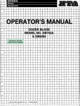
Signal Input Coupling
This procedure demonstrates the appearance of a video
signal with the different positions of the CH 2 Input Coupling
switch (see Figure 5-1).
Initial Setup
a. Press in the POWER switch button (ON).
b. Set the instrument controls to obtain a baseline trace
as follows:
Vertical
CH 2 POSITION
MODE
BW LIMIT
CH 2 VOLTS/DIV
CH 2 VOLTS/DIV VAR
CH 2 Input Coupling
Midrange
CH2
Off (button out)
0.2 V
Calibrated detent
GND
Horizontal
A AND B SEC/DIV
SEC/DIV VAR
POSITION
XlO MAG
Locked together at 5 ms
Calibrated detent
Midrange
Off (button out)
Trigger
HOLDOFF
LEVEL
MODE
SOURCE
COUPLING
SLOPE
MIN (fully CCW)
Midrange
NORM
CH2
FLD1
- for sync-negative displayed signals and 4- for
sync-positive
displayed
signals
Figure 5-1. Appearance of video signal with CH 2 Input
Coupling switch positions.
5-1
Basic Applications
2445/2465 Option 05 Operators
a. Connect a composite video signal to the CH 2 input
connector and change the CH 2 Input Coupling switch to
DC.
e. Set the TRIGGER COUPLING switch to either FLD 1
or FLD 2, depending on which field the desired line is in. The
INTENSITY control may have to be adjusted to increase the
trace brightness.
b. Obtain a stable baseline trace.
c. With the CH 2 Input Coupling switch in 1 Mfi DC, note
that the signal edges are flat.
d. Set the CH 2 Input Coupling switch to 1 Mfi AC and
note the tilt in the waveform due to the input coupling
capacitance.
e. Set the CH 2 Input Coupling switch to TV CLAMP.
Notice that the waveform no longer has tilt and has returned
to a dc-coupled appearance.
Time Interval Measurements
This procedure demonstrates how to use the At cursors
to make timing measurements on the video waveform.
a. Set the TRIGGER COUPLING switch to the UNES
position and the A AND B SEC/DIV switches to 10 MS.
b. Push in the At button.
c. Use the A REF QR DLY control to position one cursor
on the rising edge of the first sync pulse and use the A
control to position the other cursor on the rising edge of the
next sync pulse. The line interval period can now be read
directly from the upper-right corner of the crt readout. Qn a
525-line/60-Hz interiaced system, the readout should tje approximately 63,4 MS. A 625-line/50-Hz interlaced system
should produce a readout of approximately 64,0 fis.
d. Push in both the AV and At buttons simultaneously to
get the 1/At function. The crt readout now contains the line
interval frequency. Qn a 525-line/60-Hz interlaced system,
the readout should be approximately 15.8 kHz. A 625line/50-H2 system should produce a readout of approximately 15.6 kHz.
The preceding procedure measured line intervals on
those random lines of the video signal which triggered the
oscilloscope sweep. To make a time interval measurement
for a particular line within a field:
5-2
f. Adjust the FLD LINE # control until the desired line
number appears in the crt readout. Specific time measurements on that particular line can now be made.
This procedure may also be used to measure the width of
a sync pulse.
g. Set the CH 2 VOLTS/DIV, VAR, and POSITION controls so that the sync pulse exactly fills the screen tjetween
the 0% and 100% graticule lines. Enable the At function,
push in the XlO MAG button, and position the sync pulse on
screen using the Horizontal POSITION control.
h. Use the A REF OR DLY control to position one cursor
at the 50% point of the leading edge of the sync pulse (at
the center horizontal gratiucle line) and use the A control to
position the other cursor at the 50% point of the trailing
edge of the sync pulse. The sync pulse width can now be
read directly from the upper-right corner of the crt readout.
Voltage and IRE Measurements
Voltage measurements can be made on the video signal
using the AV cursors and the crt readout. In addition, IRE
measurements expressed in percentages can also be made
and displayed on the crt as a percent.
a. Push in the AV button, set the X10 MAG button out
for X1 magnification, and return the CH 2 VOLTS/DIV VAR
control to its calibrated detent. Waveform voltage measurements can now be made by using the A REF OR DLY and A
controls to position the AV cursors at the desired points of
the video signal. The crt readout will correspond to the voltage potential between the two points on the waveform.
b. Set the CH 2 VOLTS/DIV, VAR, and POSITION controls so that the back porch and the top of a 100%modulated video signal exactly fill the screen between the
0% and 100% graticule lines.
c. Any part of the waveform can now be measured in
IRE units by using the A REF QR DLY and A controls to
position the AV cursors at the appropriate positions of the
waveform. The crt readout will be a percentage which will
correspond with the IRE measurement units.
MANUAL CHANGE INFORMATION
At Tektronix, we continually strive to keep up with latest electronic developments
by adding circuit and component improvements to our instruments as soon as they
are developed and tested.
Sometimes, due to printing and shipping requirements, we can't get these
changes immediately into printed manuals. Hence, your manual may contain new
change information on following pages.
A single change may affect several sections. Since the change information sheets
are carried in the manual until all changes are permanently entered, some
duplication may occur. If no such change pages appear following this page, your
manual is correct as printed.
n
»
2
a
•X
rr
2
T
C
X
S
c
2
l^ktronix®
COMMFTTED TO EXCELLENCE
PrnH...f
MANUAL CHANGE INFORMATION
nnto-
^'^ ^-84
2445/2465 OPT 05 OPERATORS
fihangft RftforcnrpM«n.... P.rt Mn •
DESCRIPTION
EFFECTIVE ALL SERIAL NUMBERS
TEXT CHANGES
Page 1-3
TRIGGERING
Add the following to the Performance Requirements for Sync Separation.
For noninterlaced scan systems, the video signal source must start and
end with full lines of video for correct line identification in the field trigger
modes.
Page 2-3
READOUT DISPLAYS
In the second paragraph, replace the first sentence with the following.
The crt readout will display TV Thgger information when the Trigger
COUPLING switch is set to any of the TV trigger modes (FLD1, FLD2, ALT,
or LINES) and scale factors are on or when the TV (back-porch) clamp is
active and scale factors are on.
Page 3-1
Add the following section.
FILTER/GRATICULE REPLACEMENT
The plastic filter or graticule over the crt faceplate can be removed by
sliding the filter or graticule up until the bottom edge is exposed. Pull the
bottom edge out and slide the filter or graticule down.
Page 3-2
Add the following line to part 8.
Push down once on the TRIGGER COUPLING switch.
Page 3-2
Add the following section.
AUTOMATIC SYNC SELECTION
Automatic sync selection is a feature which allows the user to preselect
the polahty of sync used most often. Automatic sync selection will change
the sync to the preselected polahty when the user enters a TV trigger
coupling selection. Once TV trigger has been activated the user may
change the polarity as desired. Changing trigger coupling selections within
the TV option area will not cause the sync selection to be changed.
Page 1 of 2
000-2775-OOD
C2/0784
070-4629-00
PG 38
Product- 2445/2465 OPT 05 OPERATORS
Date:
7-16-84
Change Reference:
C2/0784
DESCRIPTION
An exerciser (EXER 63) routine controls this function. The TV option can
be set up to automatically select the desired sync when entering the TV
trigger. There are three possible selections for exer 63:
POSITIVE:
TV option will select sync positive when entering TV
trigger.
NEGATIVE: TV option will select sync negative when entering TV
trigger.
DEFSLOPE: TV option sync selection will default to the A trigger
slope,
(prior to this version MV2 DEFSLOPE has tjeen the only possible
selection)
After entering exer 63 the display will read:
TVSYNC:POSITIVE
OR
TVSYNC:NEGAT1VE
OR
TVSYNC:SLQPE DEFAULT
Selection Is controlled by the trigger coupling switch. An up push when
TVSYNC is POSITIVE will change the selection to NEGATIVE, the next up
push will change to DEFSLOPE, the next up push will return to POSITIVE.
A down push will exit exer 63 and store the last state displayed. Push the
A/B TRIG button to exit the diagnostic monitor.
Page 4-1 Slope Selection
Replace the Slope Selection paragraph with the following.
When using the TV trigger, the A trigger slope controls the polarity of sync
on which the option will trigger. For sync-negative displayed signals, set the
slope to - . When triggering on sync-positive displayed signals, set the
slope to 4-.
Page 4-4
Table 4-1
Add the following command to the table.
Header
TVSync
Argument
Argument
Comments
POSITIVE
Sync is set to positive when activating the TV
trigger.
NEGATIVE
Sync is set to negative when activating the TV
trigger.
DEFSLOPE
Sync defaults to the present value of the A trigger
slope when activating the TV trigger.
Page 2 of 2
001-0057-OOD