1
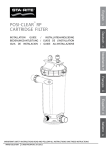
SERVICE MANUAL
for
MEDIPHOT 900E
X-Ray-Filmprocessor
Warnung: Diese Anleitung ist nur für qualifizierte Service Techniker bestimmt.
Warning: For the use of qualified service personnel only.
Avertissement: Réservé au personnel de service qualifié.
MMP89 V2.4 and up
02/2006 FR
MEDIPHOT 900E
X-Ray-Filmprocessor
Technical Specifications
Processing applications:
Cut sheets of all commonly used X-Ray films
incl. Mammography
Film thickness:
Material width:
Material length:
min. 0,10 mm
min. 10 cm (4") - max. 36 cm (14")
min. 10 cm (4")
Time in Developer:
Intake Speed:
Cycle Time:
min.15 sec
max. 84 sec
76cm/min (31inch/min)
14cm/min (14inch/min)
82 sec
459 sec
(see the table on one of the next page)
Tank capacity -
Developer
Fixer:
Wash water:
Solution heating(Fix and DEV):
Dryer:
MP 900 E
2,6 L
2,5 L
3 L
variable in a range of 18°C - 43°C
(350W Inline Heater)
warm air
Replenishment:
fully automatic.
replenishment is microprocessor controlled and
calculated from information received from sensors
measuring the width and length of material entering the
processor. Replenishment cycles are variable.
power supply:
1 / N / PE~ 230V (+6% / -10%), 50Hz, 13A, 1.7KW
(alternatives are avaliable on request)
water supply:
2-way magnetic valve, with 3/4" hose connection by using a
DVGW-approved system-separating device or pipe-separating
device.
Wash water flow rate:
Wash water supply pressure:
Wash water supply:
1,5 ltr/min when film is in process
3 - 10 bar
filtered at a temperature of 10°C - 15°C
Weight:
Empty
With solution
MP 900E
58
kg
66 kg
Technical specification subject to change without notice.
FR 02/2006
MEDIPHOT 900E
INPUT SPEED / DEV-TIME / CYCLE-TIME:
MEDIPHOT
900E
FR 02/2006
MEDIPHOT 900E
Dimensions of MEDIPHOT 900E:
FR 02/2006
MEDIPHOT 900E
FACTORY SETTINGS: MP900E
FR 02/2006
MEDIPHOT 900E
FR 02/2006
MEDIPHOT 900E
INDEX
1. INTRODUCTION
1
2. GENERAL SAFETY INSTRUCTIONS
2-6
3. PREINSTALLATION
7
4. CHEMISTRY- and WATERCIRCUTS
8,9
5. REPLENISHMENT
10
6. CHEMISTRY DRAINS / WATER DRAINS
11,12
7. INSERT THE TRANSPORT RACKS
13-15
8. THE FIRST STEPS
16
9. WORKING WITH THE FILMPROCESSOR
17,18
10. THE DISPLAY
19 - 25
11. MAINTENANCE
26
12. RECOM. MAINTENANCE EVERY 2-4 MOUNTH
27
13. SERVICE OF THE PROCESSOR
28-44
14.SOFTWARE UPDATE
45-46
FR 02/2006
Service Manual for MEDIPHOT 900E
1. INTRODUCTION
Congratulations upon your decision to buy a
COLENTA X-RAY FILMPROCESSOR.
Your purchase has been designed to meet the highest technical standards.
Some outstanding design features are:
*)
compact, space-saving design
*)
full automatic processing cycle
*)
smooth roller transport system
*)
low tank volumes
*)
electronically controlled temperature system
*)
automatic replenishment
*)
low energy consumption
This manual is an instruction for routine use of your:
COLENTA X-RAY FILMPROCESSOR.
MEDIPHOT 900E
FR 02/2006
page 1
Service Manual for MEDIPHOT 900E
2. GENERAL SAFETY INSTRUCTIONS
*)
Staff in charge of maintenance of the processor need to be thoroughly familiar with the
equipment.
*)
Only the Top Cover of the Filmprocessor may be removed by the operator (see picture
below)
.
*)
The film processor must be separated from mains prior to carrying out any maintenance. To
do so, switch the mains switch of the machine to „0“ position. Always wear safety goggles
and protective clothing when handling chemicals.
Top cover
Main switch of
the film processor
*)
The filmprocesor may not be in operation without supervision.
*)
Make sure that clothing or other objects cannot get entrapped in gear drives or similar of the
film processor.
*)
The installation, service, repair as well as the initial operation of the machine may be carried
out by qualified and trained service personnel only.
*)
Built-in safety devices may not be eluded or made inoperative. Use only original COLENTA
spare parts when exchanging failed electrical components.
*)
Do not wear any loose necklaces or bracelets!
2.1 CHEMICAL HANDLING
*)
Observe all safety technical regulations of the chemical manufacturer.
*)
Wear safety goggles and protective clothing when handling chemicals.
*)
Ensure proper ventilation of the room in which the chemicals are prepared.
*)
Spillage or overflow of chemicals has to be removed instantly.
*)
In case of contact with the eyes flush with plenty of cold water for approximately fifteen
minutes and consult an physician.
*)
Chemical disposal has to be in accordance with the local environmental codes. Contact your
local water treatment and sewer district authorities for more information.
FR 02/2006
page 2
Service Manual for MEDIPHOT 900E
2.2 IMPORTANT WARNING AND SAFETY INSTRUCTIONS
(Please read these instructions carefully.)
Processor Operation
Make sure that no long hair, loose clothing or
jewellry can get entrapped in the gear drives
or in the media transport area.
2).When handling chemicals wear protective
clothing, safety goggles and rubber gloves .
The „Service Manual for Colenta Film
Processor" is for the use of qualified
service personnel only.
3).Label storage containers properly.Avoid
storing hazardous chemicals on high
shelves or in unprotected glass containers.
Keep chemicals away from children.Do
not store chemicals in a refrigerator used
for food because they may contaminate
food or be mistaken for edibles.
The racks must be cleaned with running
water outside the Film Processor.
4).Ensure proper ventilation in the area where
chemicals are used or stored.
Do not clean the processor with running
water.
5).Observe the manufacturer’s recommendations for using and mixing chemicals.
Electrical and Mechanical Hazards
Observe all safety warnings to minimize the risk of
electrical shock,burns or equipment damage.
Photographic Film Processors are complex
machines with many electrical and mechanical
parts as well
as with a considerable amount of chemicals.
Fire Prevention
The area around the processor must be kept
clean at all times. Keep dust ,wood shavings,
scrap paper or other inflamable materials out
of the dryer compartment.
Fire extinguishers must be available in the
room where the processor is installed.
Overexposure to photographic
chemistry may cause skin irritation to
certain individuals.
PHOTOGRAPHIC CHEMICAL EMERGENCIES
AND FIRST AID PROCEDURES:
• SKIN - Rinse thoroughly with water.
• EYES -Rinse thoroughly with water and
consult a physician.
• INGESTION -Consult a physician immediately.
Chemical Handling and Accident Prevention
Misuse of almost any chemical may create
a hazard of some type.Generally photo chemicals
are not any more dangerous as most of the regular
cleaning agents. However, there is always a residual
risk. When handling chemicals observe the procedures
below.
1).Never sniff a container or open bottle to
determine its contents. A cautious sniff of
the cap or lid is safer.
FR 02/2006
page 3
Service Manual for MEDIPHOT 900E
Chemical Disposal
Waste from photographic processing normally
contains diluted chemicals. These chemicals
should be collected and disposed in accordance
with local environmental codes.Dumping
chemicals into a drain system could lead to a
pollution problem.Contact your local water
treatment and sewer district authorities before
disposing chemicals.
All plumbing must comply with local and
national codes.The DRAIN must be made of
chemical resistant and non-corrosive material.
Use PVC or equivalent
Exhaust,Temperature and Humidity
It is necessary to ensure proper ventilation
in order to receive good processing results.
Make sure that the exhaust hose of the
built-in exhaust fan is properly connected
to the exhaust air socket (Picture 1).
The built-in exhaust fan exhausts the
fumes from the filmprocessor.
These chemical fumes are corrosive. The top
cover of the filmprocessor should be removed over
night.
Room temperatures between 18-26 °C
(65-80 °F)with a relative humidity between 35%
and 75%are ideal for photographic processing
and working.
The filmprocessor is a complex
machine with moving parts such as the gear
train and media transfer components.It uses
photo processing chemicals which are irritating
to eyes,lungs and skin.High voltage is used to
power the filmprocessor.
The dryer compartment produces heat.
· High voltage may cause electric shocks,
burns or even death.
· Hands or fingers may be pinched or
injured by moving parts or when handling
heavy parts.
· Dryer compartment heat may ignite
combustible materials and cause fires.
· Eyes,skin and lungs may be irritated
by photo chemicals.Before using photo
processing chemicals always read the
Material Safety Data Sheets (MSDSs)
for information about the hazards of
the particular chemicals and how to use
them safely.
· Do not operate the film processor after
consuming alcohol or taking strong
medication.
· Do not wear jewellery or loose clothing
when operating the processor.
Electronical and Electrical Hazards
HAZARDOUS VOLTAGE CAN CAUSE
ELECTRIC SHOCK,BURNS OR EVEN
DEATH ·
Qualified service personnel must verify during
installation that the processor is permanently
and reliable grounded according to
standards in the National Electrical Code.
FR 02/2006
page 4
Service Manual for MEDIPHOT 900E
Burn Hazard
Carry out the following steps prior removal
of the top cover:
DRYER COMPARTMENT PRODUCES
HEAT -DRYER PANELS AND GUARDS
GET HOT
· Therefore do not touch dryer panels or guards
when dryer in operation
1.Train operators of the filmprocessor.
2.Switch off the main power switch
(„0“-position) and secure against
restart by locking with a padlock
(see picture below).
Corrosive Liquids
CHEMICALS MAY IRRITATE EYES,
LUNGS, SKIN AND DIGESTIVE TRACT
# Wear safety goggles,protective gloves and
chemical aprons as indicated on Material
Safety Data Sheets (MSDSs)when handling
chemistry.
# Drain tanks carefully,avoid splashing.
Always drain the system thoroughly before
working on any of the external hose systems.
# Read the MSDSs for more information
regarding the proper safety procedures for
working with photo processing chemicals.
# Do not allow untrained personnel to handle
photo processing chemicals or to operate
the filmprocessor.
Fire Hazards
Main switch of
the film processor
# To avoid hazardous situations,keep floors
and floor coverings around the processor and
associated drains clean and dry at all times.
Any accumulation of fluids outside the film
processor, should be cleaned up
immediately
DRYER COMPARTMENT PRODUCES
HEAT -PAPER OR OTHER COMBUSTIBLES CAN BE IGNITED
· Keep the area within 10 feet of the processor
clean.Do not store combustible materials,
including paper, close to the filmprocessor.
· Verify that a functional 10 lb.ABC fire
extinguisher is located closed to the processor.
FR 02/2006
page 5
Service Manual for MEDIPHOT 900E
In the event of an accumulation
of liquid due to backup,overflow or other
malfunctions of the drain associated with the
filmprocessor call a plumber or other contractor
to correct the problem with the drain.
Colenta assume any responsibility or liability
whatsoever for the service ability of any
drain connected to the filmprocessor.
Such drains are the sole responsibility
of the customer.
DRAINS must be made of chemically
resistant and non-corrosive material.
Corrosive Vapours
CHEMICAL VAPOURS MAY IRRITATE
EYES,LUNGS AND SKIN IF ALLOWED TO
ACCUMULATE IN WORK AREA
Assure an adequate supply of fresh
outdoor air through natural or mechanical
ventilation.
· Make sure that qualified service personnel
is checking the external exhaust system at
regular intervals.
Chemical Hazards
Chemicals can be the source for errors,
contaminate the waste water, irritate skin
or eyes.
Spills must be cleaned up immediately as
follows:
· Read the Material Safety Data Sheets
(MSDSs)for more information regarding
the proper safety procedures for working
with photo processing chemicals.
1.Prevent the spilled chemicals from entering
a waste water drain.
2.Clean up the spill with a moist mop or rag.
CAUTION!
When handling chemicals, especially fixer,
wear protcctive clothing, safety goggles
and rubber gloves.
If filmprocessor chemicals make contact with the
eyes,rinse them thoroughly with lots
of water.If irritation persists,consult a physician.
3.Dispose cleaning materials and collected waste
water from the clean up according to
environmental regulations and locals codes.
4.Avoid any inhalation of chemicals as
this is dangerous to health.
5.Observe all environmental regulations for
storage and disposal of waste chemicals.
6.Use this manual together with the
instructions for chemicals.
When handlingchemicals wear
protective clothing, safety goggles and rubber gloves,
FR 02/2006
page 6
Service Manual for MEDIPHOT 900E
3. PRE- INSTALLATION
*)
Site preparation, e.g., water supply, drainage electrical supply must be completed prior
installation.
3.1. LOCATION
*)
Processor can be installed "through-the-wall" or completely in the darkroom.
Required measurements can be taken from the processor specification sheet.
For "through-the-wall", a purpose built panel is required (optional accessory).
3.2 ELECTRICAL SUPPLY
*)
All electrical connections must meet national safety requirements. Correct fuses and
electrical requirement can be taken from the processor specification sheet.
Main switch of
the film processor
Power cord
3.3 WATER SUPPLY
*)
The processor must be connected to the local water supply by using a DVGW-approved
system separating device or pipe separating device.
*)
The cold water supply pipe must have a stopcock fitted connection to the processor and
should be done by using the 3/4" hose connector, supplied. Easy access to the stopcock
should be provided as it has to be opened and closed daily.
*)
A built in magnetic valve reduces water consumption to a maximum of 2,5 ltr./minute using
pressure and quantity control.
*)
It is recommended to run a second cold water supply with
2.5 meters of hosing to facilitate easy cleaning of the racks
and tanks (water supply kit - optional accessory).
Water connection und
drains in front of the
processor.
FR 02/2006
page 7
Service Manual for MEDIPHOT 900E
4. Chemistry and water circuts
Following illustrations/drawings and pictures confirms the circulation and
Washwater system of the processor:
Watervalve
Temp.-probe
Circulationpump
Heatexanger
DEVELOPER
TopView
in detail....
Valve to adjust the flowrate
of the intermediate rinse
Temp.-probe DEV
Circulationpump
Rep.
DEV
Heatexanger
DEV Replenishment inlet
FR 02/2006
page 8
Service Manual for MEDIPHOT 900E
FIXER
TopView
in detail....
Circulationpump
Heatexanger
Rep.
FIX
FIX Replenishment inlet
WATER
TopView
Watervalve
in detail....
to Wash and intermediate rinse
Cooling DEV/FIX
Valve to adjust the flowrate
of the intermediate rinse
FR 02/2006
page 9
Service Manual for MEDIPHOT 900E
5. REPLENISHMENT
When operating a processor which uses chemicals for the continuous production of plate/film it is very
important that the chemicals within the machine are keep in good working order so as to provide consistent
processing quality. To achieve this consistency we use replenishment solutions, which are formulated by
the chemical manufacturer and injected into the processor precisely for the area of material being
produced. Replenishment of the chemical tanks is done automatically using infra red sensors located at the
entrance to the processor. These sensors accurately monitor the width of material entering the processor,
this information is in then used by the microprocessor (CPU) control software to calculate the surface area
for each plate loaded into the processor. Each sensor, when covered, will generate a pulse, which is then
recorded on a decoder and counted – the more sensors that are covered then the faster the count. When
the count reaches the programmed value of pulse counts it triggers the start of a replenishment cycle.
During each replenishment cycle the replenishment pumps inject fresh solution from small storage bottles/
tank and into the corresponding ”working” tank solutions for a pre-set time.
DEV TANK
FIX TANK
Replenisherpump
for FIX
Replenisherpump
for DEV
External Developer
replenisher Tank
Cover
DEV
Standpipe
DEV FIX
Filter
USE FLOADING LID
TO PROTECT DEVELOPER
AGAINST OXYDATION
FIX
Cover
DEV
FIX
Standpipe
External Fixier
replenisher Tank
Filter
WARNING
*)
Do not use brass or copper in the drainage system.
*)
Chemistry disposal must be in accordance with local
environmental regulations.
*)
To avoid back pressure in the drain, the hoses should be
free of bends and with a constant downward gradient.
FR 02/2006
page 10
Service Manual for MEDIPHOT 900E
6. CHEMISTRY DRAINS / WATER DRAINS
To drain the filmprocessor (Developer, Fixer and the Wash) just open the drain
tubes according the illustrations below. Take care that all the mentioned drain
taps are close during re-fill up.
IMPORTANAT: Used Developer and used Fixer has to be collected in suitable
conatiners seperately.
WATER Supply Line
DRAINS for:
WATER
DEV
FIX
Drain Tubes
Lift to drain the WASH
(No-Code)
Lift to drain the FIX
(Blue-Code)
Lift to drain the DEV
(Red-Code)
Check regulary that
the rubber O-Ring is
in correct position.
FR 02/2006
page 11
Service Manual for MEDIPHOT 900E
6.1 INFRARED REPLENISHMENT SENSORBAR
The automatic replenishment system is useing an infrared-sensor-bar to detect the
incoming film area. With that information the CPU of the filmprocessor will calculate
the replenishment rate which will be need.
Sensorbar with
Infrared sensors
Replenishmentpump
for DEV
Replenishmentpump
for FIX
IMPORTANT: Special care must be taken to ensure that the processor entrance
rollers are always clean and dry – any spillage of chemical or water onto the feed tray
/ feed rollers or sensor bar must be avoided. Any spillage must be cleaned immediately.
6.2 REPLENISHMENT CONTAINERS
FIX
DEV
Standpipe
Standpipe
Filter
Filter
30L Replenishmenttank
30L Replenishmenttank
The filters, shown above, should be checked monthly and be cleaned or replaced if necessary.
WARNING: Separate the Film Processor from mains. To do so, switch the main power switch of the
processor to „0“ position. Wear safety goggles, protection gloves and clothing.
FR 02/2006
page 12
Service Manual for MEDIPHOT 900E
7. INSERT THE TRANSPORT RACKS
After cleaning or changing the chemistry, the transport racks has to be re-installed to the
processor. To do that, follow the instruction and illustration mentioned below:
WARNING: Separate the Film Processor from mains. To do so, switch the main power
switch of the Filmprocessor to „0“ position. Wear safety goggles, protection gloves and
clothing.
#
#
#
#
#
#
#
#
Wash the tanks with water, remove any deposits in the chemistry tanks.
Remove any possible algas from the washtank.
Close the the drain-tube (DEV-FIX-WASH) as mentioned on the page before.
Fill the chemistry tanks (first the FIXER, than the DEVELOPER!!) to the red maker.
(Fill carefully and slowly - prevent splashes)
Fill the Washtank to the red marker.
Insert the racks according the reference number in follqwing the sequence below. *
Fix the rack according the next page.
Close the Topcover and switch on the processor.
!
*Sequence to insert the racks:
1. DevRack into the DevTank
2. FixRack into the FixTank
3. Wash&Dry Rack into the WashTank
4. COS-A between DEV & FIX
5. COS-B between FIX & WASH
COS...CrossOverSegment
Wash-Tank
!
FIX-Tank
DEV-TANK
WASH&DRY
Film exit
COS-Blue
COS-Red
Film in
COS...CrossOverSegment
FIX
FR 02/2006
DEV
page 13
Service Manual for MEDIPHOT 900E
INSERT THE TRANSPORT RACKS
WASH&DRY
FIX (Rack2)
DEV (Rack1)
IMPORTANT:
check that the drive gears of the transport racks (DEV /
FIX / WASH) are in correct position.
WASH&DRY
FIX (Rack2)
DEV (Rack1)
FR 02/2006
page 14
Service Manual for MEDIPHOT 900E
INSERT THE TRANSPORT RACKS
WASH&DRY
FIX (Rack2)
DEV (Rack1)
COS-Blue
COS-Red
COS...CrossOverSegment
After all the racks and CrossOverSegmenents are installed,
fix them by closing the rotary joints.
Fix the racks!
Fix the racks!
FR 02/2006
page 15
Service Manual for MEDIPHOT 900E
8. THE FIRST STEPS
WARNING: Separate the Film Processor from mains. To do so, switch the main
power switch of the Filmprocessor to „0“ position. Wear safety goggles,
protection gloves and clothing.
8.1 Never switch on the processor (main switch position "1") when the
tanks (DEV/FIX/WASH) are emty. This would create serious technical
problems!!
8.2 USING THE CHEMISTRIES
*)
*)
Only use chemistry suitable for roller transport systems.
Follow instructions of chemistry manufacturers.
FIXER BATH:
*)
*)
*)
*)
*)
Empty fixer tank by opening the fix drain tap.
Remove the Fixer-rack.
Check fixer tank is free of alien material.
Close fix drain tap.
Fill fixer tank with ready-to-use-fixer solution to the red marker on the tank wall. Insert
the Fixer-rack very carefully and slowly, add hardener solution if advised by the chemistry
manufacturer.
DEVELOPER BATH:
*)
*)
*)
*)
*)
Empty developer tank by opening dev drain tap.
Remove the Developer-rack.
Check developer tank is free of alien material.
Close dev drain tap.
Fill developer tank with ready-to-use-developer solution to the red marker on the tank
wall. Insert the developer-rack very carefully and slowly. Replenishment tanks may be used
to mix the chemistry.Any remaining can be used for replenishment.
CAUTION:
Even the smallest quantity of fixer could contaminate the developer
solution. Therefore, always fill with fixer first. When removing the fixer
rack, always cover the developer tank. For removing the fixer rack
use rack carrier tray (optional accessory)
FR 02/2006
page 16
Service Manual for MEDIPHOT 900E
9. WORKING WITH THE FILMPROCESSOR
IN THE MORNING
*)
*)
*)
*)
Turn on water supply.
Check the levels of the replenishment containers (DEV&FIX)
Switch on the Filmprocessor with the Filmprocessor main switch (position „1“).
Wait for the "READY" of the processor
STARTING WORK
*)
*)
*)
*)
*)
*)
*)
Check level of the replenishment containers (DEV&FIX)
Check level of the waste containers (DEV&FIX)
Select programme
Feed through one or two of cleaning films (optional item).
During feeding films, always check the free-signal, given form the display.
Ensure first rollers pull material.
Feed large format films in straight.
IN THE EVENING
*)
*)
*)
Turn off water supply.
Switch off the main power switch of the Filmprocessor. (Main switch in position „0“)
Open water drain tap to prevent algae growths in water tank.
*)
Lift the top cover to
prevent condensation !!
FR 02/2006
page 17
Service Manual for MEDIPHOT 900E
9.1 PROCESSOR FUNCTIONS
PROGRAMMING:
Automatic processing parameters, e.g., temperature, speed and
replenishment rates, can be stored in 3 different programmes.
WARMING-UP:
Once programmed, temperature settings are accurately controlled.
Heating commences with switching on at the mains. Constant solution
temperatures are maintained in the processing tanks. Temperatures
tolerances +/- 0,2 °C are achieved by the microprocessor control unit
while the solutions are circulated by circulation pumps. When
temperature has reached PRE-SET levels, the filmprocessor enters
STANDBY mode and is ready for use.
STANDBY:
In case no material is processed - after a programmable periode of time,
since the last media has exited the filmprocessor transport, dryer and water
supply is switched off automatically. The filmprocessor goes in standby
mode and is ready for work.
ANTI CRYSTALLIZATION CYCLE
During STANDBY mode - within a programmable cycle periode - transport
and intermediate rinse bath water supply is activated - this prevent
cristallization build up on crossover rollers.
ANTI-OXIDATION
CYCLE
During STANDBY mode - and no material is processed during set time an preprogrammable ANTI OXIDATION cycle (replenishment cycle)
is available.
The additional replenishment compensates the impact of airoxidation of
the chemistry during standby mode und tops up the chemistry
levels in the tanks, compensating evaporation of the water in the
solutions during standby.
AUTO
REPLENISHMENT:
AUTOMATIC
START-STOP:
The filmprocessor comes equipped with a film area measuring facility.
Infrared sensors scan the film area touchless and when
the preprogrammed amount of film (area) entered the filmprocessor,
a replenish-cycle is activated.
Infrared sensors also automatically control the startcycle of the
filmprosessor. The filmprocessor changes from STANDBY to RUN once a
film has interrupted the light barrier. As the rollers turn, water is supplied to
the wash tank and to the intermediate rinse bath system. Once the last
film has passed through, the filmprocessor reverts to STANDBY. The film
can be taken out of the receiving basket or top cover lid.
FR 02/2006
page 18
Service Manual for MEDIPHOT 900E
10.THE DISPLAY
Number of programs
Temperature range, developer and fixer
Temperature control tolerances
Temperature measurement resolution
Developing time tolerances at max. speed
· Motor speed is quartz-stabilized and controlled by a
separate microprocessor
5
18.0 ÷ 43.0°C
±0.2°C
0.03°C
±0,2%
Display
Light1
Light2
5 manual operation
6 move cursor
7 select menu item/
change value
FR 02/2006
page 19
Service Manual for MEDIPHOT 900E
10.1 After switching on the processor
After the processor is installed and with all the components and service in place, switch
on the processor. The controller display will illuminate and confirm the software revision
monentarily.
u24
...in the display
Never switch on the processor (main
switch position "1") when the tanks
(DEV/FIX/WASH) are emty. This would
create serious technical problems!!
After the initialization-cycle is complete (it takes 1-2 sec.) the processor will start in
program1 (P1)
21.1
Light2
...in the display
...will be on
The "21.1" indicate that the current Developer temp. The flashing Light2 informs about that
an Error is existing. This is a normal status after switching on the processor, especially in
the morning and depends on the room temp. where the unit is installed. The processor
will start now to activate the heating element for the DEV, this of course to heat the DEV
to value which is programed in the microprocessor. As soon as this value is reached, the
Light2 will stop to illuminate - that confirms that no error is pending anymore.
In that case the processor is ready to process films.
NOTE: the processor will deactivate the error code 1°C before the programmed value of
the DEV is reached - but of course the heating element will still heat until the required
temp. is reached - during that the Light2 will flash, now it is possible to load film.
0,3 C° before the programmed DEV Temp., the processor will stop heating, the light2
is now OFF - the processor is now ready.
FR 02/2006
page 20
Service Manual for MEDIPHOT 900E
10.2 Error codes
As mentioned before, when Light2 is active (on), an error is existing. To see which error,
use the buttom6 on the display you will see:
Er1
Er-
use 6 again to check wether there are
more errors - until on the display will show
this confirms that no more errors are pending any
more. Following error codes are possible:.
Error Code
Action
Er1 – Cover opened.
Er2 – Developer too cold.
Er3 – Developer too warm.
Err – Motor overloaded.
Er- – no more errors.
E99 – Setup invalid;
E98 – Standby invalid;
E97 – Program invalid
??? – Temp.-probe problem
Close the top cover of the processor
Normal message after start-up, when
active during normal working
Check wether the water-tap is open. when
active during normal working Check the drive system
reprogramm and check the Setup
reprogramm and check the Standby
reprogramm and check the Program (P1 to P3)
Call service personnal
Use 6 to jump back to main page (actual Dev-Temp.).
10.3 PROGRAMPARAMETERS
The software offers the possibility to use 3 different processing-programs. They are
called P1, P2 until P5. In each of that mentioned programes, the following parameters can
be preprogrammed
# DeveloperTemp
# Replenishment amount / m²
# DeveloperTime
To see and to check the current parameters, push 7 1 time, you will get:
blinking
between:
21.1
7
21.1
Px
7
actual DEV temp.
progr. DEV temp.
(already there)
(C°)
(C°)
1 time
1 time
current
program in
t 23
Developer
time Px
(sec)
FR 02/2006
7
400
7
replenishment
amount / m²
(ml/m²)
1 time
1 time
page 21
Service Manual for MEDIPHOT 900E
10.4 Changing the program
As mentioned before, the software offers 5 different programs which can be choosen by
using the display: to do that, follow the instruction/illustrations below:
Push 5 1 time, you will get:
...in the display
Hnd
Use 6 1 time you will get:
...in the display
P1
....or P2 until P5
Use 7 to select the program (P1,P2 until P5) you want to use. When the program is
shown, push 61 time you will get
confim 71 time. After the processor
USE
finished the re-initialization cycle, the processor is now working according the new
programmparameters.
Step by step:
5
Hnd
P1
6
7
P2
6
USE
7
u24
7
P5
re-initialization cycle
7
FR 02/2006
page 22
Service Manual for MEDIPHOT 900E
10.5 Reprograming the DEVELOPER temperature
In each of the five programs, the developer temp. can be reprogrammed, this according
the specs given by the film/chemistry supplier.
To do that, use 51 time, you will get:
Hnd
...in the display
To do that, use 61 time, you will get:
USE
6
Px
...in the display
...in the display
x for P1,P2
until P5
1 time
Use again 61 time, you will get:
33.0
actual Dev.
Temp. for Px
x for P1,P2
until P5
FR 02/2006
page 23
Service Manual for MEDIPHOT 900E
Now, push again 71 time, the first digit will start flashing:
first digit
33.0
actual Dev.
Temp. for Px
Again with 7, change the number of the first digit to the values you wish. Use 6 to
move to the second digit and change the number with 7 in the same way. Use again
6 to move now to the last digit and again 7 to change the number you need.
first digit
33.0
last digit
second digit
6
33.0
actual Dev.
Temp. for Px
actual Dev.
Temp. for Px
7
7
6
33.0
actual Dev.
Temp. for Px
x for P1,P2
until P5
7
Now, when the new value is shown, the last digit is still flashing, push 6 until (approx. 3
sec) you can see:
PrG
This confirms that the new value is stored.
At least the processor will start one re-initialization cycle:
u24
To change the DEV-temp. for other programs (P1 - P2....P5) in the same way:
change the program in the way as disreibed on page 19 - 7.4.
FR 02/2006
page 24
Service Manual for MEDIPHOT 900E
10.6 Manual Mode
It might be necessray to run the transport by hand, this for example to process film
regardless the current DEV-temp. To start the dive motor by hand use 51 time
you will get:
...in the display
Hnd
Now push 71 time , you can hear the running. To stop the motor push again 7 . To exit
this mode, use 5
10.7 Distance between films
To prevent film jams, some minimum distance between the films is needed. This needed
distance is fixed in the processor setup.
# Load film: as soon as the sensorbar
recognized that film is there, the Light2
will be on.
Light2
# During loading in film, the Light2 will be
on to confirm this. At this status, never
load any films additional!!
# When Light2 is off (there will be a beep
as well) the processor is ready to load film
again.
FR 02/2006
page 25
Service Manual for MEDIPHOT 900E
11. MAINTENANCE
The filmprocessor is designed to produce consistent high quality production with the minimum
of maintenance.
Regular maintenance minimizes the chances for equipment failure and loss of
processing quality. A a well trained person has to be responsible for performing the maintenance
of the filmprocessor and must be familiar with the operation and function of the
processor as well.
1. Daily maintenance
*)
Check levels of the external replenishmener tanks If necessary mix fresh solution.
*)
Cleaning feed tray.
*)
Cleaning spray-bar-guide for the fixer
*)
Before starting production we advise to feed some cleaning films to remove any
overnight residue.
2. Weekly maintenance
*)
Wipe external surfaces of film processor / enclosures / panels
with a wet cloth to remove any chemical / dirt deposits.
*)
Inspect and clean the wash tank and intermediate water rins drains. If algaes present
then the should be removed, in such a case we suggest to use a proven algae control
system
*)
Check the COS (CrossOverSegments) remove any deposits.
*)
Take out the guide of the COS and clean them as well.
Guide
COS
DEV
Guide
DRY
COS
FIX
FR 02/2006
WASH
page 26
Service Manual for MEDIPHOT 900E
12. RECOMMENDED MAINTENANCE EVERY 2-4
MONTHS.
(Period is subject to filmprocessor useage.)
Good processing quality and the reliable operation of a filmprocessor is dependent upon regular
and careful cleaning. Every 3-6 months, the chemicals in the tanks should be drained.
A chemical cleaning of the processing tanks and wash tank is recommended. Always follow
safety warnings as described in section 1 when cleaning the filmprocessor.
Prior to carrying out any maintenance, switch off the power at the main power switch
(position "0") ensuring it cannot be accidently switched back on.
*)
*)
*)
*)
*)
*)
*)
*)
*)
*)
*)
*)
*)
*)
*)
*)
*)
*)
*)
*)
*)
Switch off the main power switch of the film processor first (position „0“).
Remove the top cover of the filmprocessor.
Drain individual tanks by open the draintaps in front of the filmprocessor.
Remove rack assemblies (water / DEV / FIX, see item 2.1) and put them aside.
Close taps and fill all tanks with water or better with suitable cleaning solution
until the red mark inside the tanks are reached.
Put the racks back into the tanks of the filmprocessor and close the top cover.
Switch on the filmprocessor and start some replenishment cycles. The hoses will be
cleaned with water as well. Also start the transport of the filmprocessor, the racks has to be
in. Let the filmprocessor run for 10 to 15 minutes.
Switch off („0“ position)the main power switch of the filmprocessor and drain the
filmprocessor tanks again.
NOTE: Use cleaning solution according to the manufacturer´s instructions.
After tank cleaning, the developer- and wash-tank should be filled twice with fresh water
(eventually use neutralizer recommended by manutacturer). Let the filmprocessor run for
approximately 10 minutes again. Check all external (outside of the filmprocessor)
hose connectors (outside of filmprocessor) and fittings for leaks.
Drain all tanks.
Remove the water / DEV / FIX Racks and check for:
-worn gears
-damaged or worn bearings
-loose screws
-scratched or bent film guides
-plastic flat springs in developer bottom underturn.
All repairs must be carried out by qualified service personnel.
Check the inside of the tank for contamination and alien substances.
Clean the rollers well.
Close the drain taps of all 3 tanks.
Fill developer and fixer tanks with fresh chemicals to the required level (1st fixer, 2nd
developer)
Fill wash tank.
Re-install the racks carefully. Take care of correct sequence of the racks is followed and
make sure the gears are in the right position. Secure the racks.
Insert the respective suction pipe to the correct external replenisher tank.
Re-install the top cover and switch on the filmprocessor.
Process test films.
FR 02/2006
page 27
Service Manual for MEDIPHOT 900E
13. SERVICE OF THE PROCESSOR
Warnung: Diese Anleitung ist nur für qualifizierte Service Techniker bestimmt.
Warning: For the use of qualified service personnel only.
Avertissement: Réservé au personnel de service qualifié.
The COLENTA MP900E X-Ray Filmprocessor is equipped with a small 7 segment
OperatorDisplay - this display allows the operator, limited in a small range, to set
some different processing parameters - described in the Instruction Manual. For
service, a seperate Display has to be installed - this only for reprograming or
service and trouble shooting.
Display for Service
(Optional)
Operator Display
(Standard)
Switch off the power at the main power switch
(position "0") ensuring it cannot be accidently
switched back on.
100cm cable
Open the Cover by
opening the 2 fixing
screws.
Cover E-Box
FR 02/2006
page 28
Service Manual for MEDIPHOT 900E
13.1 INSTALLATION OF THE SERVICE DISPLAY
Install the Service display following the illustrations below:
ST7
COOLING VALVE
ST6
REP. PUMP
CIRC. PUMP
ST5
ST4
HEATER DEV. DRYER HEATER+FAN
ST3
ST2
L
N
ST8
DRYER FUSE
MOTOR HIGH ST8
N
N
N
N
N
N
L
L
L
L
L
L
F6
F5
F4
F3
F2
F1
U8
C10
ST11
1
F8
2
4
5
6
LD5
U10
LD4
U9
LD3
LD2
T0,63A
ST14
ST19
ST13
POWER SUPPLY
ST12
MAIN FILTER
ST9
SENS. BAR
U11
PHILIPS CPU
ST15
ST10
U12
LD6
RS232
3
U13
Led_Display&Kbd
110V
TEMP PROBE EXT.DISPLAY Additional
Operator Display
(Standard)
230V
VOLTAGE SELECT
U 15
RS TTL
LEVEL COVER
L
F9
MAIN FUSE
MOTOR LOW
SETUP
T6,3A
LD1
T1,6A
4
T0,63A
re
T0,63A
3
T0,63A
2
or
T0,63A
br
T0,63A
1
N
T8A
F7
ST17
bl
ST1
PDB MINI_04_2004
P89C668
MAINS
WASH VALVE
Sensorbar
Operator Display
(Standard)
Display for Service
(Optional)
Temp. Probe DEV
Display for Service
(Optional)
When the service display is installed as mentioned before, switch on the processor.
NOTE: At this moment, the cover of the E-box is open so there is a risk of electrical
shocks, ensure that nobody is getting contact with components and/or wirings inside
the E-Box.
FR 02/2006
page 29
Service Manual for MEDIPHOT 900E
13.2 WORKING WITH THE NEW DISPLAY
13.2.1 AUTOMATIC MODE
The processor is designed to work without operator assistance. Under normal
circumstances the operator will use the front panel only to check the process
parameters and progress.
To scroll through the pages, press
1)
. - Press
8
to jump back to main page.
4
2)
55% DONE
T1: 33.0 (33.0)
3)
Rep1 400ml/sqm
Speed 27cm/min
4)
Tank1 time 25s
Dry to Dry 247s
Add 14 pls
Rdy 10 pls
1 back light ON/OFF
2 check errors /alarm shutdown
3 setup mode
4 back to top menu
FR 02/2006
5 manual operation
6 move cursor
7 select menu item/
change value
8 scroll page down
page 30
Service Manual for MEDIPHOT 900E
1) 55% Done is the progress indicator. It means that 55% of the developing process are
done. When 100% are reached, the processor will go to standby.
T1=32.4ºC confirms the actually measured temperature in the DevTank. The value shown
in the brackets is the programmed temperature.
2)
Rep1 400ml confirms the amount of replenishment for the Developer .
Note: To supply fresh chemistry to the Fixer as well, a double head replenishment pump
is installed. Read more on this issue on page....
Replenishmentpump
for DEV
Replenishmentpump
for FIX
Speed: Linear speed of the Film "going" trough the processor in cm/min.
3)
Tank1 time is the time the media needs to pass through tank 1 (Developer)
Dry to dry is the length of the complete processing cycle (leading edge to heading edge)
4)
Add 14 pls confirms the additional added pulses for the input section of the DEV
Rdy 10 pls confirms the safety distance between loading films
FR 02/2006
page 31
Service Manual for MEDIPHOT 900E
13.2.2 PROGRAMMING PROCEDURES
Switch on the processor it will start in work mode. Make sure that no media is
being processed, re-programming is enabled only during standby.
Press
. The programming menu will appear:
3
Program Setup
Standby Service
Use
, to move the cursor to Program and confirm with
6
You will get:
.
7
P1 Modify
FR 02/2006
page 32
Service Manual for MEDIPHOT 900E
Press
Use
7
to change the number of the program you wish to modify (P1 to P5).
, to move the cursor to Modify and use
6
7
to confirm.
The programe (P1,P2 or P3) consists of three pages:
2)
1)
R1 0400 ml/sqm
Tank1 time 023 s
T1 33.0°C
3)
To change the programed values:
# use
Save
6
to move the courser to the
digit you want to modify.
Cancel
# use
7
to add "+1" to the value (..8-9-0-1-2..)
# use
8
to jump to the next page (..8-9-0-1-2..)
# save / exit
NOTE: It's not possible to go back to the previous
page. In case you programmed something wrong,
start again form page one.
Use
8
to scroll through the pages. Use
to Cancel and confirm with
7
7
to confirm your changes or move the
as well to abort.
FR 02/2006
page 33
Service Manual for MEDIPHOT 900E
During saving, you might will get the message "Out of range" which confirms that one or
more inputs are not allowed - even ot of range.
Out of range
After 2 seconds the message will disappear and you will be taken back to re-programme
the values. A parameter that was too high will be automatically reset to the maximum
possible value. A parameter that was too low will be reset to the minimum possible value.
This can be used if you want to program extreme values - for instance you want to use
the shortest developing time possible, but you don’t remember the value. In this case
just programme 000. After the “Out of range” message, the developing time will be reset to
the minimum. Just select Save once again.
To go back to work mode, press
.
4
During programing by using the
service display, on the operator
display will be shown:
Pro
FR 02/2006
page 34
Service Manual for MEDIPHOT 900E
13.2.3 CHANING THE PROGRAM
To use another programme, use
5
you will get:
Start P1 Use 33.0
Monitor
With
, move the cursor under P1.
6
Press
With
to change the programme number.
7
, move the cursor to Use and confirm with
6
Press
.
7
to jump back to main page.
4
Note: a cyclic redundancy check is used to verify the data being read from the non-volatile memory.
If some damage occurred to the program data, or the programme was never set up properly,
you will get an error message Program invalid. The solution is to go to programming mode
and re-program the data. This error will occur also if the EEPROM chip has been replaced in
which case it contains random data.
FR 02/2006
page 35
Service Manual for MEDIPHOT 900E
13.2.4 MANUAL START / STOP
The manual start/stop is possible only when no media is being processed.
During the processing the corresponding menu items are not selectable - you
can’t move the cursor there.
To run the motor manually:
Press
With
5
, move the cursor under Start and select it with
6
.
7
This will run the motor. The menu item Start changes to Stop.
You can stop the motor by selecting Stop.
When you start the motor manually, this will be indicated on the main page as
M1 instead of P1.
13.2.5 DISPLAY ILLUMINATION ON/OFF
In a dark room, it might be necessary to switch off the display backlight to prevent
exposure. The
1
button toggles the backlight on/off.
When the backlight is off, all the buttons except
1
are disabled.
This is done to prevent pressing buttons by accident in a dark room. Switching the
display off is a good idea if the processor is left unattended. This will reduce the
chances for unauthorized people to operate the machine.
13.2.6 AUTOMATIC START
The processor will start automatically when media is fed, except in case the developer is
too cold - more than 1ºC below the programmed. In this case, feeding the media will not start the
processor. Instead you’ll get the message,
Tank1 too cold
which will disappear after 2 seconds.
If you need to feed a film regardless of the low developer temperature, run the machine
in manual mode.
FR 02/2006
page 36
Service Manual for MEDIPHOT 900E
13.2.7 ERRORS
If an error occurs, the indication P1 (or M1) will alternate with Er. If this happens
Press the
button. This will stop the beeper and bring you to the error menu, so you
2
can check what the processor is telling you.
In case more than one error occurred, press
rest of them. Press
8
to scan the
to jump back to main page.
4
Tank1 too cold
When the processor switched on at the beginning
of the working hours ,it is expected to have low
temperatures in the tanks.For this reason, the Er
indication will be present, but without alarm.
If, however, the temperature drops during
normal work, the alarm will be activated.
Error Code
Action
Er1 – Motor overloaded.
Only appears when the re-pulses given from the
motor are not the same as the CPU of the processor
are expacted them. The reason could be a blocked
drive system. In that case for the first step, take out all
CrossOverSegments and try again. 2nd take out all the
racks/dryer and try again. When after that 2 tests the
message is gone, check the racks, eventually replace
them. In case the message is still active, check the
drive gears below the tankbody. If they are OK,
replace the motor and/or main board.
Er2 – Cover opened.
Close the top cover of the processor. In case the
message is still present, check the magnets (2!)
connected to the main board. Eventually replace them.
Er3 – Developer too cold.
Normal message after start-up, when active during normal
working, check the circulation pump, the heating element
for the DEV (over temp. fuse!! installed on the
heatexchanger housing) Check wether all outputs are
driven - from the main borad. (Service Mode)
Er4 – Developer too warm.
Check wether the water-tap is open. when
active during normal working - Check wether the output on
the main board is driven (Service Mode). In case yes,
replace the 2 way Water valve.
Er- – no more errors.
no more errors
FR 02/2006
page 37
Service Manual for MEDIPHOT 900E
Drive system
Drive Motor
Circulation pump
2 way water valve
Temp. fuse
Heatexchanger
E99 – Setup invalid;
Check all the SETUP values, reprogram them and save
again. Check the WEB for software update.
E98 – Standby invalid;
Check all the STANDBY values, reprogram them and
save again. Check the WEB for software update.
E97 – Program invalid
Check all the STANDBY values, reprogram them and
save again. Check the WEB for software update.
Err – Problem with Temp.
probe DEV
Replace the temperature probe of the DEV
FR 02/2006
page 38
Service Manual for MEDIPHOT 900E
13.2.8 STANDBY OPTIONS
The Processor supports an anti-oxidation and a anti-crystallization cycle.
That means, when in standby, the processor will start the transport of the rollers and the
wash on regular intervals in order to prevent any crystallization or build ups on the rollers
(Anti-crystallization). The anti-oxidation cycle activat, in free programmable time intervals,
replenishment cycles. This will prevent oxidation of the the chemistry.
During such a cleaning cycle, the display
will look like this.
P1 Cleaning 30%
T1=32°C (32,0)
During such a cycle the processor will
accept media. It's not necessary to wait
to the end of the cycle.
Press3, use 6 to move the courser to "Standby" use 7 to confirm; use 8 to scroll
through the pages:
1) SB replenishment
100ml each 6h
8
2) SB self-cleaning
20cm each 10min
The processor will activat a 100ml replenishment cycle
each 6 hours.(Anti-oxidation-cycle)
The processor will activat 3 roller turns (1 roller turn ≅
8 cm) each 3 min.(Anti-crystallization-cycle)
8
3) Switch ON Dryer
for 5 min.
8
4) DR On each 10min
for 01 min
After switching on the processor (Main switch) the
dryer will start heating for 5 min. countinually this heat
up the dryer and the dryer components.
When the the processor is on, but not in use for longer
time, the dryersystem would loose his heat. To prevent
this, each 10 min the dryer (heater&fan) will start work.
Save Cancel
FR 02/2006
page 39
Service Manual for MEDIPHOT 900E
13.2.9 MONITOR MODE
The feature can be used to check current status of the processor. That mens it confirms
wether different outputs are driven or not, the sensorbar is occupied or not.....
see the table below for more detail:
Motor OFF
Spd=34
v=00
P=000
t=000
Main drive Motor is working or not
Speed of the Main drive motor
needed for internal calculation
needed for internal calculation
needed for internal calculation
8
S-Bar: - - - - - Area=0,0000 sqm
Confirms, which sensor is currently active
Confirms the ingoing filmarea
8
P89c668 MM_V24
ID=000-0000
r=1
Confirms the software code
Option for Identification No.
needed for internal calculation
8
H1=1/0
Cir=1/0
Rep=1/0
Col=1/0
Wsh=1/0
Hd=1/0
Output Heater driven or not...1=on, O=off
Output Circulation pump driven or not...1=on, O=off
Output Replenishment pump driven or not...1=on, O=off
Output Cooling Valve driven or not...1=on, O=off
Output Wash Valve driven or not...1=on, O=off
Output Fan for Dry driven or not...1=on, O=off
FR 02/2006
page 40
Service Manual for MEDIPHOT 900E
13.2.10 SETUP OF THE PROCESSOR
Press3, use 6 to move the courser to "SETUP" use 7 to confirm; use 8 to scroll
through the pages:
1) Tank1
0042 pls
Machine 0248 pls
Start Point of the processor for counting pulses.
Total pulses trough the processor.
8
2) Gear
Pump
219 pls
02.6 ml/s
Gear is the number of motor pulses corresponding to 1m advance of the
material. It is needed to calculate the processed film area (for the replenishment) and the processing speed in cm/min.
Pump is the number of milliliters per second of the replenishment pump.
Needed to allow programming the replenishment in milliliters.
8
3) Sensor distance
060 mm
Sensor distance is the distance between two sensors of the sensorbar needed for the film area calculation.
8
4) Replenish after
each 0.125 sqm
Replenish after. This is that area, after one replenishment cycle has to be
activated.
5) Ready 0030 pls
after film left
Defines the safety distance between loading film (free signal for
the next fim).
6) Add 14 pulses
before start
Due the fact that the optical sensorbar is installed before the film will
enter to the DEV, a calculation factor has to be added.
Machine
7)
Additional Run
001cm
Save Cancel
DRY
For safety reasons, the moto will run 1cm additional after
the exited the dryer rollers
TANK1
DEV
FIX
WASH
Main drive motor
with tachometer
NOTE: The shaft of the main drive motor has a tachometer installed . When the drive
motor starts the tacho will rotate to generate a speed counter which sends pulses to
the Processor CPU. By using these pulses the CPU is able to accurately control the
transport speed/timing sequences
FR 02/2006
page 41
Service Manual for MEDIPHOT 900E
It is possible to see data and to change working data in the SETUP menu but to
save any new data entered into the SETUP menu then it will be necessary to insert
a jumper on the main board of the processor:
15W
15W
17W cos 0,67
35W cos 0,69
WASH VALVE
COOLING VALVE
REP. PUMP
CIRC. PUMP
ST7
ST6
ST5
350W
1141W cos 0,99
HEATER DEV. DRYER HEATER+FAN
ST4
ST3
ST2
L
N
ST8
DRYER FUSE
MOTOR HIGH ST8
N
N
N
N
N
N
L
L
L
L
L
L
F6
F5
F4
F3
F2
F1
L
F9
MAIN FUSE
MOTOR LOW
U8
C10
ST11
1
F8
2
5
6
U10
LD4
U9
LD3
LD2
T0,63A
ST14
ST13
ST19
POWER SUPPLY
ST12
ST9
SENS. BAR
U11
LD5
PHILIPS CPU
ST15
ST10
U12
LD6
RS232
4
U13
Led_Display&Kbd
110V
TEMP PROBE EXT.DISPLAY Additional
SP
MAIN FILTER
230V
VOLTAGE SELECT
U 15
3
RS TTL
SETUP LEVEL COVER
T6,3A
LD1
T1,6A
4
T0,63A
re
T0,63A
3
T0,63A
2
or
T0,63A
br
T0,63A
1
N
T8A
F7
ST17
bl
ST1
PDB MINI_04_2004
P89C668
MAINS
50W COS 0,68
SP........SetupProtection
JUMPER
Don't forget to remove the jumper
when the reprogrammong is done.
FR 02/2006
When selecting Save in the setup
menu, the program will refuse to
save the data unless this wire
jumper is present.
page 42
Service Manual for MEDIPHOT 900E
13.2.10 SERVICE / Electronic check (Inputs-Outputs-Components)
Press3, use 6 to move the courser to "SERVICE" use 7 to confirm you will get:
Inputs
Outputs
Mem LED Motor SB
Inputs
Cov=0
Lev=0
SP=0
Th=0
ID=0
VD=0
7
1=On and 0=Off
Inpout for Coverswitch
1=On and 0=Off
Input for Level Switch (Option,Not in use)
1=On and 0=Off
Input for Setup jumper
Re-pulses given from the motor disk
Input for speed regulation
Output for speed regulation
Inputs
7
H1=0
Cir1=0
Rep1=0
Col=0
Wsh=0
Hd=0
1=On
1=On
1=On
1=On
1=On
1=On
Mem
and
and
and
and
and
and
Output for HeaterH1
Output for Circulation Pump
Output for Replenishment Pump
Output for Magnetic Valve: Cooling
Output for Magnetic Valve: Wash
Output for DryerFan
7
Load default val
Medical NDT Exit
LED
0=Off
0=Off
0=Off
0=Off
0=Off
0=Off
........Medical when the processor is used for
medical X-Ray application
........NDT when the processor is used for
industrial X-Ray application
7
Use to check the LEDs of the operator Display
Motor
Speed:
Ph_Del:
T=0
SB
Speed:
S-bar:
7
0 +0
Used to check the motor
needed for internal calculation
needed for internal calculation
7
0 +------
no. of sensor
Sensor check (optical sensorbar)
FR 02/2006
page 43
Service Manual for MEDIPHOT 900E
14. SOFTWARE UPDATE
Warnung: Diese Anleitung ist nur für qualifizierte Service Techniker bestimmt.
Warning: For the use of qualified service personnel only.
Avertissement: Réservé au personnel de service qualifié.
Whenever a Software update available,we are announcing that on our Homepage.
We rcommend to check this side regulary to see wether a new software is
available. In case yes, you can download the update free of charge.
#
http://www.colenta.de /X-ray/X-Ray Processors/MP900E
#
click to Software update and enter the Password: MINI56xf
#
Dowload the software and store the file (hex) on your hard disc
#
Check wether some additional informations are available
Follow now the illustrations below to update the processor.
Firstly you need to install the program "Flash Magic" on your system. To do that,
open the folder MINI_FlashMagic supplied on that CD or download from WEB as
well. Follow up the installation routine. When the installation was done successfully,
start the program, open the pull-down menu "Options", confirm "Advanced Options"
open the register card "Timeouts" and set the values as shown below:
FR 02/2006
page 44
Service Manual for MEDIPHOT 900E
#
Switch off the Processor
#
Place the jumper on ST15 as shown.
#
Connect the download cable
- on your PC / RS232 - 9pin
- on the MainBoard of the processor on RS232
JUMPER ST15
JUMPER ST15
#
Switch on the Processor (the service display will confirm that the
CPU is now in program mode by showing black lines
#
Start the program "FlashMagic"
FR 02/2006
Don't forget to remove the jumper
when the reprogramming is done.
page 45
Service Manual for MEDIPHOT 900E
add1)
Compare the values shown on the image before with the
values mentioned on your FlashMagic program.
add2)
Make sure that the box " Erase all Flash+Security" is choosen.
add3)
Browse the new Download file
add4)
make sure that nothing is chossen
add5)
Push the button Start
NOTE: In case an Error is indicated right after starting, restart the processor,
restart the program and try again.
IMPORTANT: After succefully updating the software, remove the update
jumper (mentioned on the page before), put the setup jumper in position and
enter the setup by pushing 3 (service display!) . Choose Service, move
over to MEM you will get : Load default val
Medical NDT Exit
According the application: choose Medical or NDT
FR 02/2006
page 46
NOTES:
NOTES:
NOTES:
0
1
2
3
4
5
6
7
8
9
10
11
12
13
F8
PDB - ST1 (MAINS)
T8A
L
L (Page 2/1)
N
N (Page 2/1)
PE (Page 2/1)
F7
T0,63A
R6
S1
3
TC1
RC6
R4
U
RC5
IC09
LD2
IC10
IC11
R5
U
LD3
R3
U
RC4
RC3
R2
U
RC2
U
2
+5V
LD4
IC12
LD5
IC13
LD6
L N
2
F6 T0,63A
PDB ST7
1,5mm²
(AWG 16)
1
L
PDB ST5
L´
PDB ST4
N
N
L´
PDB ST3
2
3
4
1
2
1
N PE
2
1
Y1
2
1
Name
2
2
T>
2
50°C
28-11-2005
HANDLER
fh
DIN EN 60950 Z.Nr.
RDM8-2_01
T>
T>
M6
M7
MAGNETIC VALVE
WASH VALVE
COOLING VALVE REP. PUMP
TANK 1
(DEV.)
1
Zust. Ers. fuer
T>
Y2
MAGNETIC VALVE
MEDIPHOT 900E
Datum
Bearb.
Gepr.
Norm
N
L´
1
MAIN-DRIVE-MOTOR
PE
Datum
N
L´
F2 T1,6A
4
NETZANSCHLUSS
POWER CONNECTION
N~/230 50/60Hz
13A 1,7kW
Zust. Aenderung
PDB ST6
F3 T0,63A
115V
M1
1
N
N
F4 T0,63A
1
T>
3
L
F5 T0,63A
L´
115V
2
1 2 3 4
LABORTECHNIK
A-2700 Wr. Neustadt
REP. PUMP
TANK 2
(FIX.)
M2
CIRC. PUMP
TANK 1+2
(DEV.+FIX.)
STROMLAUFPLAN RDM8-2
WIRING DIAGRAM RDM8-2
350W
1
ST17
black
brown
orange
red
ST 8
TANK1+2 - HEATER
(DEV.+FIX.)
Blatt 1
von 3
Bl.
0
1
2
3
4
5
6
7
8
9
10
11
12
13
L (Page 1/12)
N (Page 1/12)
PE (Page 1/12)
IC08
LD1
R1
RC1
U
F1 T6,3A
PDB ST2
N
L´
DETAIL DRAWING
DRYER HEATER
DRYER HEATER
T>
black
T>
1100W
blue
brown
black
blue
T>
C1
1,5µF
Zust. Aenderung
Datum
Name
Datum
Bearb.
Gepr.
Norm
28-11-2005
HANDLER
fh
DIN EN 60950 Z.Nr.
RDM8-2_02
0
Zust. Ers. fuer
LABORTECHNIK
A-2700 Wr. Neustadt
STROMLAUFPLAN RDM8-2
WIRING DIAGRAM RDM8-2
Blatt 2
von 3
Bl.
3
4
5
6
7
8
S71
9
10
S72
5
2
3
4
6
SENS. BAR
LCD1
Led_Display&Kbd
1
ST12
TEMP PROBE EXT.DISPLAY Additional
6
1
6
6
7 Seg. Driver
PB5
yellow marking
gelbe Markierung
+12V
SCL
GND
+5V
SDA
-12V
DRIVER
6
ST-1
BZ1
BUZZER
ST13
ST9
6
6
DISPLAY
ST14
ST15
ST10
1
13
1
SWITCH
COVER
LEVEL COVER
SWITCH
COVER
1
SETUP
blue
PB6
12
ST11
black
PB7
11
TEMP PROBE TANK 1
(CODE 0)
2
RS232
1
RS TTL
0
1
6
SENSORBAR
DRIVER
Sbar MINI R10.2003
Sensor 0
Zust. Aenderung
Datum
Sensor 1
Name
Datum
Bearb.
Gepr.
Norm
Sensor 2
28-11-2005
HANDLER
fh
DIN EN 60950 Z.Nr.
RDM8-2_03
Sensor 3
0
Zust. Ers. fuer
Sensor 4
LABORTECHNIK
A-2700 Wr. Neustadt
Sensor 5
STROMLAUFPLAN RDM8-2
WIRING DIAGRAMM RDM8-2
Blatt 3
von 3 Bl.
2
3
4
50W COS 0,68
5
6
7
8
15W
15W
34W cos 0,67
35W cos 0,69
WASH VALVE
COOLING VALVE
REP. PUMP
CIRC. PUMP
ST7
ST6
ST5
ST4
9
350W
10
HEATER DEV. DRYER HEATER+FAN
ST3
ST2
N
N
N
N
N
N
L
L
L
L
L
L
F6
F5
F4
F3
F2
F1
LEVEL COVER
SETUP
5
T8A
F8
2
U 15
3
6
RS232
RS TTL
4
U11
LD5
U10
LD4
U9
LD3
LD2
T0,63A
PHILIPS CPU
ST15
Led_Display&Kbd
Datum
U12
ST14
ST13
ST19
POWER SUPPLY
ST12
ST9
SENS. BAR
U13
LD6
ST10
Zust. Aenderung
U8
C10
ST11
1
L
F9
LD1
T1,6A
MOTOR LOW
T0,63A
4
T0,63A
re
T6,3A
N
MAIN FUSE
T0,63A
3
T0,63A
2
or
T0,63A
1
ST1
L
N
ST8
bl
13
PDB MINI_04_2004
P89C668
F7
ST17
12
1141W cos 0,99
DRYER FUSE
MOTOR HIGH ST8
br
11
MAINS
1
Name
Datum
Bearb.
Gepr.
Norm
110V
TEMP PROBE EXT.DISPLAY Additional
28-11-2005
PDB_MINI_04_2004
HANDLER
_P89C668
fh
DIN EN 60950 Z.Nr.
MAIN FILTER
230V
VOLTAGE SELECT
0
0
Zust. Ers. fuer
LABORTECHNIK
A-2700 Wr. Neustadt
SICHERUNGSBESTÜCKUNG RDM 8-2
PDB RDM 8-2
Blatt 1
von 1 Bl.