1
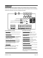
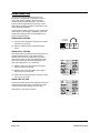
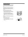
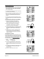
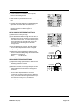
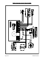
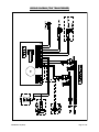
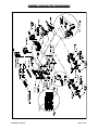
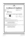
Micro-Pro II MP-200 / 300 Series Instruction Manual 0901052 Rev: H (05/13) Page 1 of 16 TABLE OF CONTENTS Introduction ........................................................................................................... 3 Circuit Board Diagram .......................................................................................... 3 Installation ............................................................................................................ 4 Plumbing .............................................................................................................. 4 Probe Installation .................................................................................................. 5 Electrical ............................................................................................................... 5 Rinse Operation.................................................................................................... 6 Sanitizer Operation ............................................................................................... 7 Probe Operation ................................................................................................... 8 Probeless Operation ............................................................................................. 9 Wiring Diagram (Single Transformer) ................................................................. 10 Wiring Diagram (Two Transformer) .................................................................... 11 Assembly Diagram (Single Transformer) ............................................................ 12 Assembly Diagram (Two Transformer) ............................................................... 13 CSA Certificate of Compliance ........................................................................... 14 Warranty Information .......................................................................................... 16 Knight Locations ................................................................................................. 16 CAUTION: All electrical connections to the Micro-Pro II system should first be verified with a meter. Application of incorrect voltage will permanently damage the unit and is not covered under warranty. Avoid wiring to any power source that has large fluctuations in voltage and/or is prone to surges. Refer to the wiring diagram in this manual for all power and signal connections. CAUTION: Do not mount the unit in the direct path of steam. This can short circuit and permanently damage the unit. Mounting the unit on the side, on the back, or on the vents of the dishwasher may cause thermal overload and damage or hinder the performance of the unit. CAUTION: The Micro-Pro II has high voltage connected to the transformer(s). Always disconnect power when servicing the unit. Page 2 of 16 0901052 Rev: H (05/13) INTRODUCTION Micro-Pro II warewash systems provide the versatility of probe or probeless detergent control through advanced microprocessor design. With the capability of controlling up to three products, the choice of liquid or dry detergent, and the choice of single or dual transformer configuration, virtually any warewash application can be accommodated. The Micro-Pro II warewash control features simplicity and versatility. RINSE SPEED SANITIZER SPEED CONCENTRATION OR RECHARGE ALARM DELAY OR INITIAL CHARGE Single transformer Dual transformer POTENTIOMETER SETTINGS SLIDE SWITCH SETTINGS Rinse Speed Pot: Adjust the speed at which the rinse Probe/Probeless Switch: Allows you to select pump runs. Sanitizer Speed Pot: Adjust the speed at which the sanitizer pump runs. Concentration or Recharge Pot: In ―probe mode‖ sets detergent concentration strength. In ―probeless mode‖ sets the pump time necessary to recharge the detergent concentration. Alarm Delay or Initial Charge Pot: In ―probe mode‖ sets the time before the alarm sounds if the probe senses low detergent concentration. In ―probeless mode‖ sets the pump time necessary to initially charge the detergent concentration. Jumper Settings: Single Transformer: Sets the unit for single transformer see page 10 for wiring. Dual Transformer: Sets the unit for dual transformer see page 11 for wiring. 0901052 Rev: H (05/13) operation with or without a probe Door/Conveyor Switch: Sets alarm delay range for probe mode. Sets initial charge timing range for probeless mode. Low/High Range Switch: Used if operating in probe mode. Selects concentration ranges. Low/High Audio Switch: Sets the alarm volume. Sanitizer Select Switch: Sets the sanitizer pump to run with rinse feed, or detergent feed. On/Off Rinse Limit Switch: When on, stops the rinse pump after 30 seconds. 3-Second Rinse Delay Switch: When on, delays the rinse pump for three seconds. 6-Second Rinse Delay Switch: When on, delays the rinse pump for six seconds. NOTE: If the 3-second and 6-second rinse delay switches are both on, the rinse pump will be delayed for nine seconds. Page 3 of 16 INSTALLATION PRESSURE SWITCH PLUMBING (optional) Mount the unit on a nearby wall (using suitable hardware) or on top of the dishwasher if desired. Try to keep the unit within three feet from the final rinse line to avoid long tubing runs. Install pressure switch kit. Thread the male end of the ―tee‖ fitting into the rinse line on the dishwasher, and connect the poly tubing from the rinse pump into the end opposite the male threads, using the checkvalve provided. Thread the pressure switch into the remaining opening on the tee, perpendicular to the male threaded end. CAUTION: Do not mount the unit in the direct path of steam. This can short circuit and permanently damage the unit. Mounting the unit on the side, on the back, or on the vents of the dishwasher may cause thermal overload and damage or hinder the performance of the unit. Check all applicable plumbing and electrical codes before proceeding with the installation. This will help to ensure that the system is installed in safe and suitable manner. A wiring schematic of the dishwasher should be used as reference for making electrical connections — this is typically provided by the dishwasher manufacturer if one cannot be located on the machine itself. PLUMBING RINSE & SANITIZER PLUMBING The following installation steps apply for rinse and sanitizer pumps alike. (1) Install the provided 1/4" tube x 1/8" NPT injection fitting into the side or bottom of the dishwasher rinse line between the rinse solenoid valves and the rinse jets. If necessary, drill a 11/32" hole and tap to 1/8" NPT. Use of a saddle clamp may be desired on copper rinse line for better support. (2) Cut a suitable length of 1/4" OD poly tubing and connect between the discharge (right) side of the pump’s squeeze tube and the injection fitting. (3) Cut a suitable length of 1/4" OD poly tubing and connect between the suction (left) side of the pump’s squeeze tube and the pickup tube provided. Be sure to draw tubing through the end of the pickup tube. (4) Hand-tighten the compression nuts on both the injection fitting and pickup tube. Plastic ties can be used to cinch around the connections where the poly tubing is inserted into the pump’s squeeze tube. Page 4 of 16 LIQUID DETERGENT PLUMBING (1) Install the provided bulkhead fitting through a wall of the wash tank (above water level). If an existing mounting hole cannot be located, use of a 7/8" hole saw or punch may be desired. (2) Cut a suitable length of 1/4" OD poly tubing and connect between the discharge (right) side of the detergent pump’s squeeze tube and the bulkhead fitting. (3) Cut a suitable length of 1/4" OD poly tubing and connect between the suction (left) side of the detergent pump’s squeeze tube and the pickup tube provided. Be sure to draw tubing through the end of the pickup tube. (4) Hand-tighten the compression nuts on both the bulkhead fitting and pickup tube. Plastic ties can be used to cinch around the connections where the poly tubing is inserted into the pump’s squeeze tube. DRY DETERGENT PLUMBING (1) A powder or solid type feeder (not provided) should be used for dispensing dry detergent products. Follow the instructions included with the detergent feeder for installation, and recommended water temperature/pressure. (2) Cut a suitable length of 1/4" OD copper tubing (not provided) and connect between the input side of the water solenoid and the water source. Maximum recommended water temperature is 140°F (60°C). (3) Cut a suitable length of 1/4" OD copper tubing (not provided) and connect between the output of water solenoid to a powder or solid detergent feeder. (4) Carefully tighten the compression nuts on the water solenoid — over tightening may cause solenoid to leak. Tighten connections to the water source and detergent feeder as needed. 0901052 Rev: H (05/13) PROBE INSTALLATION (if required) DETERGENT POWER SIGNAL (1) Install the probe in the wash tank below the water level. It should be away from incoming water supplies, near the recirculating pump intake, and 3 to 4 inches from corners, heating elements, or the bottom of the tank. If an existing mounting hole cannot be located, use of a 7/8" hole saw or punch may be desired. A detergent power signal is required to activate the detergent probe sensing or probeless initial charge. (2) Connect leads from the terminals on the probe to the ―probe‖ terminals on the circuit board. (1) Remove all power from the dishwasher. (3) For best results, use 18 AWG multi-stranded copper wire for the probe connection. Avoid running the wire near high voltage AC lines. ELECTRICAL Turn off all power before wiring the control. Check with a voltmeter to ensure power is off. MAIN POWER CONNECTION (single transformer configuration only) Some versions of the Micro-Pro II are provided with only one step-down transformer. Connect the high voltage side to any 115/208/230 VAC power source that is ―on‖ when the dishmachine is ―on‖ (i.e. mains switch on dishmachine). NOTE: The transformer provides power to both the detergent and rinse circuits. The Micro-Pro II will only operate detergent or rinse when electrically signaled. To wire main power connection: (1) Check the voltage of the main power source and make sure that it matches one of the three available input voltages (115/208/230 VAC) of the transformer inside the Micro-Pro II. (2) Remove all power from the dishwasher. (3) Connect leads from the main power source to the appropriate wires on the transformer. * CAUTION: The Micro-Pro II unit has high voltage connected to the transformer. Always disconnect main power when servicing the unit. Check the dishwasher for a power source that is active during the washcycle only (example: the magnetic contactor that controls the washpump motor) and verify voltage. (2) Connect leads from the detergent signal source to the appropriate terminals of the detergent transformer (if so equipped) or to the detergent signal terminals on the circuit board (for single transformer versions). The Micro-Pro II circuit board will accept a detergent power signal of 14 - 240 VAC. RINSE POWER SIGNAL In addition to running the rinse pump, the rinse power signal also triggers the detergent ―recharge‖ injection if probeless mode is selected (1) Check the dishwasher for a power source that is active during the rinse cycle only (example: rinse solenoid or rinse cycle light) and verify voltage. If a direct signal can’t be located on the dishwasher, a pressure switch can be used to provide a signal (see next section below). (2) Remove all power from the dishwasher. (3) Connect leads from the rinse signal source to the appropriate terminals of the rinse transformer (if so equipped) or to the rinse signal terminals on the circuit board. The Micro-Pro II circuit board will accept a signal of 14 - 240 VAC. PRESSURE SWITCH RINSE ACTIVATION An optional remote pressure switch kit is available for dishwashers that do not have a rinse power signal. The pressure switch provides a rinse power signal when the switch is activated by pressure in the dishwasher’s rinse line. (1) Remove all power from the dishwasher and the dispenser. (2) For Two Transformer units, wire main power to the Rinse Transformer. (3) See Page 10 for Single Transformer wiring and page 11 for Two Transformer wiring. 0901052 Rev: H (05/13) Page 5 of 16 RINSE OPERATION The rinse pump will operate whenever the rinse transformer is energized (if so equipped) or when a rinse power signal is applied to the circuit board, whether directly from the dishwasher, or by using a pressure switch (single transformer version). A rinse delay feature and rinse limit feature maximize the rinse pump operating capabilities. A prime button, located on the front cover, will allow the rinse pump to run at full speed, regardless of the rinse potentiometer setting. Power must be applied to the system to prime the pump. RINSE SPEED SETTING (1) Turn the rinse potentiometer clockwise to increase speed of the rinse pump (2) Adjust as needed to achieve the best sheeting action. CLOCKWISE TO INCREASE RINSE SPEED RINSE DELAY SETTING This feature delays the operation of the rinse pump for a programmed time once the rinse power signal is received. This function is typically used to conserve rinse agent injection on door-type dishwashers (using with conveyor machines is not recommended). The rinse delay settings are 3, 6, or 9 seconds. (1) Slide the upper rinse delay switch to the right to delay the rinse for 3 seconds. (2) Slide the lower rinse delay switch to the right to delay the rinse for 6 seconds. (3) Slide both rinse delay switches to the right to delay the rinse for 9 seconds. SLIDE RIGHT TO ACTIVATE RINSE LIMIT SETTING This feature will stop the rinse pump after 30 seconds of continuous rinse power signal, conserving rinse agent on dishmachines that fill through the rinse valve. Slide switch to ―rinse limit‖ to activate. SLIDE LEFT TO ACTIVATE Page 6 of 16 0901052 Rev: H (05/13) SANITIZER OPERATION A selector switch sets the sanitizer pump to operate with detergent feed, or with rinse feed. The sanitizer pump will run simultaneously with detergent or rinse, whether using probe or probeless mode, rinse delay or rinse limit. A prime button, located on the front cover, will allow the sanitizer pump to run at full speed, regardless of the sanitizer potentiometer setting. Main power must be applied to the system to prime the pump, a signal is not necessary. SELECTING SANITIZER OPERATION Sanitizer with detergent: When the control is set to this mode, the sanitizer pump will run simultaneously with the detergent pump (or solenoid). Sanitizer with rinse: Injecting sanitizer into the rinse line is required for low temperature dishwasher applications. When the control is set to this mode, the sanitizer pump will run simultaneously with the rinse pump. Choose if you want the sanitizer pump to run with the detergent, or rinse. Slide the switch left or right to select your choice. SLIDE LEFT OR RIGHT TO ACTIVATE SANITIZER SPEED SETTING (1) Turn the sani potentiometer clockwise to increase speed of the sanitizer pump CLOCKWISE TO INCREASE (2) Adjust as needed to achieve the required sanitizer amount. SANITIZER SPEED 0901052 Rev: H (05/13) Page 7 of 16 PROBE OPERATION With the detergent power ―on‖, the conductivity probe senses detergent concentration. When concentration drops below the setpoint, the control automatically turns on detergent feed. Low and high concentration ranges allow easy setting on all types of water conditions. When the detergent concentration is within 15% of the setpoint, the control automatically pulse feeds (3 seconds on / 2 seconds off) to prevent over-use of chemical. SLIDE LEFT TO ACTIVATE An ―out of product‖ alarm will automatically sound if the detergent setpoint is not reached in a specific time period. CONCENTRATION SETPOINT ADJUSTMENT (1) With low range selected, slowly adjust the detergent concentration pot clockwise a few degrees. Detergent will pulse feed, then stop. (2) Using a chemical titration kit, test detergent concentration of the wash water. Continue to increase the pot until the desired setpoint. (3) If at full clockwise position of concentration pot and wash water concentration is not strong enough, turn pot back full counter-clockwise. Switch to high range. SLIDE LEFT TO ACTIVATE CLOCKWISE TO INCREASE DETERGENT CONCENTRATION (4) Slowly adjust pot clockwise until detergent feed begins, then stops. Using chemical titration kit, continue adjusting pot until desired concentration setpoint is reached. ALARM DELAY SETTING If the detergent setpoint is not achieved within the time set on the alarm delay pot, the alarm will sound and the unit will continue to feed. If the detergent setpoint is still not reached within a second time frame (double the first) the alarm will stay on, and detergent feed will stop. (1) Delay time settings are: Door 1 to 64 seconds Conveyor 1 to 128 seconds SLIDE RIGHT TO ACTIVATE CLOCKWISE TO INCREASE (2) For conveyor type dishwashers, adjust the alarm delay to be slightly longer than the time it takes for the unit to achieve the setpoint with a fresh tank of water. ALARM (3) For door type dishwashers, the alarm setting should be calibrated to 5 - 10 seconds less than the washcycle timing. (4) Select low or high volume for the alarm. SLIDE LEFT OR RIGHT TO ACTIVATE Page 8 of 16 0901052 Rev: H (05/13) PROBELESS OPERATION Controls detergent concentration without a probe, based on timed detergent feed. Initial charge time feeds detergent to the concentration setpoint when dishmachines are initially filled. Recharge time feeds detergent to maintain detergent setpoint as rinse water dilutes the dishmachine. Door or conveyor switch selection optimizes SLIDE RIGHT TO ACTIVATE probeless operation for different types of dishwashers. INITIAL CHARGE DETERGENT SETTINGS (1) Select door or conveyor setting. (2) For dishmachines that fill through the rinse valve, a detergent signal is not necessary for initial charge if the control is set to door. The control senses by the rinse signal when the rinse has been on over 30 seconds and runs the detergent for the initial charge amount. (3) For all other types of machines, the initial charge amount will be dispensed each time a detergent signal is applied. (4) Adjust the charge potentiometer clockwise for the amount needed to initially charge the washtank with detergent. The ranges are: Door 1 to 64 seconds Conveyor 1 to 128 seconds SLIDE LEFT OR RIGHT TO ACTIVATE CLOCKWISE TO INCREASE CHARGE RECHARGE DETERGENT SETTINGS (1) Adjust the recharge potentiometer to the amount of detergent needed for one rack. The range is 0 – 10 seconds. (2) With door selected, the recharge detergent amount will be dispensed one time when a rinse signal is received. CLOCKWISE TO INCREASE RECHARGE (3) With conveyor selected, the recharge detergent amount will be dispensed after a 12 second continuous rinse signal. It will continue to dispense every 12 seconds if the rinse signal remains on (i.e. two racks in a conveyor train, two detergent recharges). 0901052 Rev: H (05/13) Page 9 of 16 WIRING DIAGRAM (SINGLE TRANSFORMER) Page 10 of 16 0901052 Rev: H (05/13) WIRING DIAGRAM (TWO TRANSFORMER) 0901052 Rev: H (05/13) Page 11 of 16 ASSEMBLY DIAGRAM (SINGLE TRANSFORMER) Page 12 of 16 0901052 Rev: H (05/13) ASSEMBLY DIAGRAM (TWO TRANSFORMER) 0901052 Rev: H (05/13) Page 13 of 16 Page 14 of 16 0901052 Rev: H (05/13) 0901052 Rev: H (05/13) Page 15 of 16 DISCLAIMER Knight LLC does not accept responsibility for the mishandling, misuse, or non-performance of the described items when used for purposes other than those specified in the instructions. For hazardous materials information consult label, MSDS, or Knight LLC. Knight products are not for use in potentially explosive environments. Any use of our equipment in such an environment is at the risk of the user, Knight does not accept any liability in such circumstances. WARRANTY All Knight controls and pump systems are warranted against defects in material and workmanship for a period of ONE year. All electronic control boards have a TWO year warranty. Warranty applies only to the replacement or repair of such parts when returned to factory with a Knight Return Authorization (KRA) number, freight prepaid, and found to be defective upon factory authorized inspection. Bearings and pump seals or rubber and synthetic rubber parts such as ―O‖ rings, diaphragms, squeeze tubing, and gaskets are considered expendable and are not covered under warranty. Warranty does not cover liability resulting from performance of this equipment nor the labor to replace this equipment. Product abuse or misuse voids warranty. FOOTNOTE The information and specifications included in this publication were in effect at the time of approval for printing. Knight LLC reserves the right, however, to discontinue or change specifications or design at any time without notice and without incurring any obligation whatsoever. KNIGHT LLC, Knight Headquarters Tel: 949.595.4800 Fax: 949.595.4801 Page 16 of 16 USA Toll Free Tel: 800.854.3764 Fax: 800.752.9518 A Unit of IDEX Corporation (www.knightequip.com) Knight Canada Tel: 905.542.2333 Fax: 905.542.1536 Knight Europe Tel: 44.1293.615.570 Fax: 44.1293.615.585 Knight Australia Tel: 61.2.9725.2588 Fax: 61.2.9725.2025 Knight N. Asia Tel: 82.2.3481.6683 Fax: 82.2.3482.5742 Knight S. Asia Tel: 65.6763.6633 Fax: 65.6764.4020 0901052 Rev: H (05/13)