1
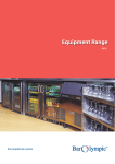
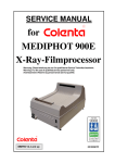
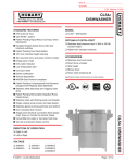
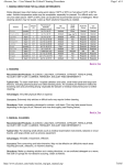
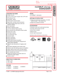
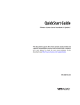
HI TEMP WAREWASHERS
INSTRUCTION,
MAINTENANCE & SERVICE
MANUAL
INTRODUCTION
Welcome to JET TECH "creating
endless possibilities!"
This manual was created specifically for service technicians. We
have included information to help troubleshoot problems and
facilitate resolving those problems, electrical schematics, exploded
views and detailed parts lists. General information pertaining to
our hi-temp ware washers will be covered in this section. Specific
information on our current models will be covered in separate sections, model by model.
While in the field, you may come across earlier generations of JET
TECH machines. General operation of these machines is similar if
not identical to our current models. However, certain parts may be
unique to these machines. This information is readily available
from our office. We have endeavoured to make this manual as
accurate as possible. If you find a discrepancy or can't find certain
information, please contact us. We will be glad to help you.
Updates and modifications will be issued as the information
becomes available.
JET-TECH SYSTEMS
7014 Cote de Liesse
Montreal, Quebec H4T 1E7
Tel.: 888-275-4534 (888-ASK-4-JET); 514-737-9701
Fax: 514-342-3854
e-mail: [email protected]
WARRANTY
MANUFACTURERS LIMITED WARRANTY
Jet Tech Systems Corporation (Jet Tech) hereby warrants all new warewashers bearing the name "JET TECH" and
installed within the continental United States of America or Canada to be free from defects in material or workmanship,
under normal and regular usage and operation, for a period of one (1) year following the date of original installation,
(unless specified otherwise ) but in no event can exceed eighteen (18) months from the date of shipment from the
factory.
If a defect in material(s) or workmanship is detected; or found to exist within the stated period above, Jet Tech, at its
sole discretion, shall either repair or replace any original equipment manufacturers part which has proven to fail within
the machine; providing that the equipment has not been altered or tampered with in any manner, has been installed
correctly as per the owners manual, and maintained and operated in complete accordance with this manual.
The labor cost to repair or replace any part proven to be defective, as per above clause(s), shall be covered by Jet
Tech Systems, within the continental United States of America or Canada; provided that: prior authorization for this
labor was approved by Jet-Tech Systems, the service work was performed by an authorized Jet Tech service agency;
and that this agency installed an original and genuine Jet Tech part in the machine. Any repair work performed by a
non-authorized service depot remains the sole responsibility of the user, and Jet Tech Systems will not be held
responsible. The installation of any generic part will not be valid; and therefore voids this warranty. All
authorized labor coverage shall be limited to regular hourly rates only. Any supplemental hourly rates or charges, such
as weekends or emergency premiums remain the responsibility of the user.
Jet Tech Systems Corp. (Jet Tech) hereby states that: warranty travel time shall be limited to, and without exception, a
round-trip total of two (2) hours OR mileage up to a maximum of one hundred (100) miles round-trip. Any charges
exceeding those stated herein must have prior authorization by the factory.
Exceptions to above warranty are: (A) Damages resulting from shipping, handling or abuse. (B) Incorrect installation
and/or connections. (C) Adjustments or calibration of any thermostats or timers. (D) Faults due to lack of regular
maintenance or cleaning of any internal part(s). (E) Replacement of any wearable items such as: glasswasher curtains,
or peristaltic squeeze tubing or gaskets. (F) Excessive lime, mineral, alkali or hard water conditions and (G) Poor
results due to: use of an incorrect type of detergent (for non-commercial type applications), and excessive or
inadequate water temperature(s) or pressure conditions.
JET TECH SYSTEMS CORPORATION STATES THAT THERE ARE NO OTHER WARRANTIES, EXPRESSED OR
IMPLIED, THAT ARE NOT SET FORTH HEREIN, JET TECH SYSTEMS CORPORATION SHALL ASSUME NO
OTHER RESPONSIBILITY, EITHER DIRECT OR NON-DIRECT, OR BE LIABLE FOR ANY OTHER OR ADDITIONAL
LOSS OR DAMAGE WHETHER BEING DIRECT OR CONSEQUENTIAL, AS A RESULT OF ITS EQUIPMENT.
JET TECH SYSTEMS CORP.
7014 Cote de Liesse Montreal Quebec
CANADA, H4T 1E7 Tel: (514} 737-9701
Toll Free: (888} ASK-4-JET Fax: (514}
342-3854 E-Mail:service @ jet-tech.com
Web: www.jet-tech.com
Warranty:
One year parts & labor (Continental USA and Canada).
Exceptions: Model "Piper" - 90 days labor
& One year parts.
The manufacturer reserves the rights to alter design and specifications without notice.
SERVICE CALL REGULATIONS
JET TECH ware washers are warranted as specified in the MANUFACTURERS LIMITED WARRANTY.
We will pay for:
1. Labor to replace a defective part, as per the attached Allocated Times Schedule.
2. Travel time, as specified in the MANUFACTURERS LIMITED WARRANTY. (See page 4)
3. JET TECH original replacement parts supplied from service company inventory
We will not pay for:
• More than one man on a service call.
• Waiting time. Call for an appointment, if required.
• Unauthorized labor charges.
• Travel time exceeding the MANUFACTURERS LIMITED WARRANTY.(See page 4)
• More than one service call for the same problem.
• Adjustment or calibrations, as specified in the MANUFACTURERS LIMITED WARRANTY.(See page 4)
• Replacement of small items (pilot light, screens, jets).
• Cleaning or regular maintenance.
• Overtime or weekends charges (time and a half, or more)
• Problems due to improper installation.
• Problems due to improper water supply temperature or inadequate/excessive water pressure.
• Problems due to inadequate/excessive electric supply.
• Disconnecting of hard plumbing or removal of counter tops, etc.
WE ARE HERE TO HELP YOU WITH DIAGNOSTIC OR SERVICE PROBLEMS.
Call us toll free at 1-888-275-4538 for assistance.
Our standard procedure is to invoice all parts shipped for WARRANTY REPAIRS. The invoice will be credited
upon return of defective parts used for WARRANTY REPAIRS.
YOUR INVOICE MUST INCLUDE THE FOLLOWING INFORMATION:
1. Warranty Repair Authorization Number.
2. Model and serial numbers.
3. Problem reported.
4. Detailed description all charges including dates, hours worked and work done.
5. Reason for part failure.
6. Indicate the general state of the equipment, cleanliness and if abuse is apparent.
We expect that your work is warranted by your company for at least 90 days.
ALLOCATED TIMES
These are the allocated times for servicing Jet Tech products under warranty. If an item is
missing, please call our office for the information.
PARTS
Diagnostic of problem
Vacuum cylinder AM except 747, F22
Vacuum cylinder 747, F22
Vacuum cylinder hose AM except 747, F22
Vacuum cylinder hose 747, F22
Wash arm manifold-upper
Wash arm manifold-lower
Wash arm axle
Rinse Elbow -upper
Rinse Elbow -lower
Door catch
Door catch mechanism, parts
#
CODE
10528
10528
10529, 15519
11580
12007
12008
12017
12021
12021
12049
12049,12050,
12052,12054,
TIME (Hours)
.5
1.25
.50
1
.50
1
1.75
.5
.75
1
.5
.5
10470,10489,
60258,10435,
60012,10415
Stainless panels
12062,12003,
12063,12002,
15507, 15504,
15505,15506
.75
Booster tank
12064,15515,
10129,15548
2
Solenoid Valve AM except 747, F20, F22
20568,20569
ELB
1.5
Solenoid valve 747, F20, F22
Electronic Noise Filter
Door Switch
20569
20018
20035,20536,
20548
ELB
F
MP
.75
.5
.75
Pilot Light
Power Switch
Relay
Booster Element
20042
20044,20500
20067
20080,20069,
20084
LL
TL
BR
RB
.5
.5
.75
.75
Tank Element
20080, 20069,
20084
RV
.75
Timer
20088, 20075,
20504
MT
.75
Relay Tank Element
Relay Booster Element
Relay Wash Pump
Thermostat-Tank Element
Thermostat-Booster Element
Peristaltic Detergent Pump
Digital Temperature Display
Air Pressure Switch
20105
20105
20105
20110
20119
20023, 20545
20108,20514
20053, 20058,
20059,20192,
RV
BCB
CCMPL
TV
TB
MPD
TC
PS
.75
.75
.75
.5
.5
.75
.5
.5
20525
Rinse Aid Pump
Cycle Start button
Drain Pump
20199
20519
40229, 20429
TC
MPS
.75
.5
.75
Wash pump on 727 & 737
40028, 40226
MPL
1.5
ALLOCATED TIMES
PARTS
Wash pump on PIPER, F16, F18
Wash pump on 747, F20, F22
Tube for chemical injector
Rinse feed tubing
Door hinges
#
CODE
TIME (Hours)
40248, 40242,
20240
40230,40236,
40255,40258
60564
60565
MPL
1.5
MPL
.75
.75
1.25
.5
WARRANTY CLAIM PROCEDURES
When a service call is placed by JET TECH, a dealer, distributor, end user or other, it does not necessarily mean that
the service call will be covered by warranty. If we request a service call, we will fax all the details available to us at
the time including customer information as well as the reported problem. We will also advise you if the equipment is
still within the warranty period.
If the equipment is within the warranty period, we will also FAX a WARRANTY AUTHORIZATION NUMBER,
often listing the parts that may be required to complete the repair as well as the allocated times to diagnose the
problem and install the recommended parts. If the problem is other than what was reported, please contact our service
department.
If a customer places a service call outside of our regular business hours Monday-Friday (Eastern Time) we ask that
you use your best discretion and notify us on the next business day.
All claims must be received at our office within 30 days of completing the work. We reserve the right to withhold
payment when:
• The defective part is not returned for inspection.
• The defective part failed because of negligence, improper installation, unauthorized servicing or improper use of the
equipment.
• Missing documents/Information.
MODIFICATIONS AND UPDATES
PART#
MODELS
SERIAL #'s
15507
15506
20500
20500
20500
20149
727
9569886-
F18/DP
737DP
727DP
F16/DP
9901607980087198007069800065-
CHANGE
NEW TOP PANEL #15683
NEW BACK PANEL #15684
THE WHITE DRAIN PUMP BUTTON
MUST BE HELD TO ACTIVATE THE
DRAIN PUMP AND WILL NO LONGER
LOCK IN THE ON POSITION
(Part# Remains the same)
TECHNICAL CHARACTERISTICS
MODEL
GENERAL DIMENSIONS
WEIGHT
Tank Cap.
SIZE-ACTUAL
Height
(mm/inch)
820.00
32.25"
Width
(mm/inch)
500.00
19.75"
Depth
(mm/inch)
500.00
19.75"
Kg
737
850.00
600.00
600.00
72.73
747
33.50"
1485.00
58.50"
23.75"
698.00
27.50"
23.75"
720.00
28.40"
155.45
749.00
29.50"
850.00
33.50"
508.00
20.00"
600.00
23.75"
508.00
20.00"
600.00
23.75"
47.73
1320
52.00"
625.00
24.50"
610.00
24.00"
86.36
F-22
1524.00
60.00"
710.00
27.95
721.00
28.40"
155.45
PIPER
518.00
20.40"
503.00
19.80"
470.00
18.50"
29.09
Flow
Pressure
Hot Water
Qty / Cycle
727
F-16
F-18
F-20
(Liters)
Lbs
52.73
Cap.
(Liters)
(US gal)
8.0
(US gal)
4.8
116
2.11
12.0
1.27
6.5
160
3.17
18.0
1.72
10.2
342
4.75
11.0
2.7
3.2
105
72.73
Booster
3.0
28.0
0.87
8.0
160
7.35
26.0
2.11
8.0
190
7.25
18.0
2.20
10.2
342
4.75
8.0
2.7
2.5
64
2.11
0.65
OPERATION PARAMETERS
MODEL
Kg/cm 2
Liters
psi
727
2.1
2.5
2.1
2.1
2.1
2.1
2.1
2.1
60
3.8
2.1
60
208-220
1 Phase
14.4
120
208-220
1 Phase
22
120
208-220
46
24
15
70
208-220
1 Phase
3 Phase
1 Phase
180
208-220
1 Phase
22
180
208-220
1 Phase
34
120
208-220
1 Phase
3 Phase
46
24
13.6
12.5
70
140
60
0.5
Seconds
140
1.0
1.9
30
AMPS
140
0.79
30
PIPER
60
3.0
Phase
140
0.79
30
F-22
60
3.0
VOLTS
140
0.5
30
F-20
60
1.9
Cycle
140
1.0
30
F-18
60
3.8
Power Requir.
140
0.79
30
F-16
60
3.0
Electrical
Requirem.
F
0.66
30
747
c
US gal
30
737
Water Temp
(Ideal)
140
110
208-220
Above parameters are subject to change without notice. Please check with the factory for most current
specification data.
180
UNDER COUNTER INSTALLATION
• Install legs on machine
• Make sure the machine is leveled.
• If a counter is put on top of the dishwasher, it is preferable if the
counter can be removed easily for servicing. If the counter is fixed,
leave half an inch (minimum) between the counter and the top of the
unit.
TABLE FOR UTILITY CONNECTIONS DIMENSIONS SEE PAGE 11
MODEL
PIPER
F16
F16DP
F18
F18DP
F20
F22
727
737
747
SIDE A
mm
inch
mm
inch
mm
inch
mm
inch
270
190
7.5
9.1
7.5
9.1
9.5
305
365
17
15.3
380
19.9
15
80
12
408
320
15
12.6
380
18.1
180
15
15
15
50
2
50
2
2
50
2
380
7.2
20.1
380
50
185
7.1
21.4
2
50
2
510
380
50
460
50
545
7.2
16
2
3.3
7.1
7.1
3.15
85
185
1.5
50
3.3
2
9.6
180
3.3
2
180
1.5
38
85
50
245
3.3
1.5
14.3
1.6
38
85
50
14.3
12
390
1.5
11.6
42
3.7
85
38
365
12
9.5
19.9
11.6
SIDE F
95
3
38
295
305
SIDE E
74
12.4
295
230
240
SIDED
315
14.7
230
190
mm
305
inch
mm
380
inch
mm
505
SIDE C
375
10.6
mm
240
inch
mm
430
inch
mm
505
inch
inch
SIDE B
2
380
15
15
DIAGRAM FOR UTILITY CONNECTIONS
THE CONTROL PANEL
OPERATION
F-18DP
Before operating the machine, ensure that the electrical
power, water supply and drain connections have been made as
per the installation instructions. Ensure that the overflow pipe
is correctly set in its place (inside the wash tank). The overflow
pipe should never be forced into its position.
Familiarize yourself with the gauges, buttons and indicator
lights on the control panel. Check that there is sufficient rinse
additive and if your machine is equipped with a liquid
detergent pump, confirm that there is sufficient detergent as
well.
• Press the Square Green Power Button ¬. The Power Indicator
Light - will illuminate (as well as the Digital Temperature
Gauges ® ¯, if so equipped). If the wash tank is empty, the
machine will start to fill. Always keep the door closed during
this time. When the machine has filled to its required water
level, the elements will then raise the rinse and wash water
temperatures automatically. It will take approximately 15-20
minutes in order to obtain the optimum temperatures (185°F in the booster and 140°F in the wash tank). The Ready
Indicator Light ° will illuminate to indicate that the machine is ready for its first load.
• Fill the basket with dishware and trays then push the basket into the machine. If you are using a powder detergent, add
the required amount (usually about one full tablespoon) in the wash tank and close the door. If you are using liquid
detergent with a chemical pump system (optional) detergent will be added automatically. DO NOT use domestic dish
soap.
NOTE: Whenever starting with the initial fresh water after fillup, it is recommended to place 1 -2 full tablespoonfuls of
detergent (if you are using powder detergent) on the filters in
addition to the regular amount per batch. Use a commercial dish
detergent, as recommended by your supplier. Using too much
may cause damage to the pump seals.
• It is more economical to wash when the basket is fully loaded.
It is also important not to overload the basket. Water should
always be able to spray freely around the dishware and trays.
• Press the round black Cycle Start Button ±. The Cycle
Indicator Light ² will illuminate. The cycle starts and consists of
a wash, a brief pause and then a rinse. Another basket can be
filled while the first one is being washed. The Cycle Indicator
Light ² will extinguish to signal the end of the cycle. Remove the basket from the machine.
OPERATION
NOTE: It is recommended to change the wash water at least twice per day (after each peak period). Press Square Green
Power Button 1 to the off position. Twist & pull up the overflow pipe and allow the machine to drain fully. The White
Drain Pump Button ³ must be activated on models so equipped.
• Rinse the tank out with clean water and remove any particles of food or debris. Do not flush debris down the drain of the
dishwasher. Remove and clean the filter(s). Replace the filter(s) and overflow pipe in their proper positions. Close the door
leave the machine empty at the end of the day or if the machine will not be in use for more than a few hours.
ELECTRICAL STAGES OF THE MACHINE
All JET TECH high temperature washers operate in the same basic manner. Ensure that the proper electrical, water supply and drain connections have
been made, that the overflow tube (stand-pipe) is properly positioned in the washtank and the machine is level.
1. Press the GREEN POWER BUTTON SWITCH (TL) and the POWER ON (LL) indicator light will illuminate as well as the digital temperature gauges
(TR) (if so equipped).
2. If the washtank is empty, the water inlet valve (ELB) will open and the washtank will start to fill through the rinse arms. The door switch (MP) is
bypassed and the fill cycle will continue even if the washer door is opened. NOTE: On models so equipped, the automatic drain pump (MPS) and/or the
liquid detergent pump (MPD), are energized at the same time as the water fill valve (ELB). The water level is controlled by an air trap in the washtank
and an air pressure switch (PS). As the water level increases, air pressure from the air trap is directed to the pressure switch (PS). When the preset
pressure is attained, the pressure switch transfers power from the fill valve (ELB) to the booster thermostat (TB).
3. If the rinse water temperature is below the preset level, the thermostat energizes the booster element (RB) (through coil (BCB), activating contactor
(CCB) on some models). When the proper rinse water temperature is attained, power is transferred to the wash tank thermostat (TV).
4. If the wash water temperature is below the preset level, the wash thermostat (TV) energizes the wash tank element (RV) (through coil (BCV)
activating contactor (CCV) on some models). When the proper wash water temperature is attained, power is transferred to the READY (LP) indicator
light. IMPORTANT: THE TWO ELEMENTS ARE NEVER ENERGIZED AT THE SAME TIME. THE BOOSTER ELEMENT ALWAYS HAS
PRIORITY OVER THE WASH TANK ELEMENT.
5. The READY (LP) light indicates that the temperatures are ideal for a wash cycle. It is normal for this light to cycle on and off as the elements maintain
the proper rinse and wash temperatures
6. Press the BLACK CYCLE START BUTTON (TC). This activates a micro relay (BR). This momentary relay energizes two internal micro switches
(CR1 & (CR2). When CR1 is closed, it bypasses the CYCLE SWITCH (TC), keeping the relay (BR) closed. CR2 energizes the timer motor (MT) and the
CYCLE INDICATOR LIGHT (LC) illuminates, starting the wash cycle.
7. As the timer motor (MT) starts to turn, the cam closes the first timer micro switch (Ml) and opens the circuit energizing the relay (BR). This new
connection bypasses the relay (BR) and keeping the timer motor (MT) and the CYCLE INDICATOR LIGHT (LC) energized. This micro switch stays
closed for the length of the wash cycle.
8. One or two seconds after the wash cycle is initiated, the second timer micro switch (M2) is closed. M2 energizes the wash pump(s) (MPL) (through
coil (BCMPL) activating contactor (CCMPL) on some models), starting the wash cycle.
9. At the end of the wash cycle, timer micro switch M2 opens, stopping the wash pump (MPL), sending power to timer micro switch (M3). Micro switch
(M3) energizes the water inlet valve (ELB), starting the rinse cycle. NOTE: On models so equipped, the automatic drain pump (MPS) and/or the liquid
detergent pump (MPD), are energized at the same time as the water fill valve. (ELB). At the end of the rinse cycle, the water inlet valve (ELB) closes and
CYCLE INDICATOR LIGHT (LC) extinguishes.
Any of stages 2 through 5 may activate simultaneously during any of the wash cycle stages 6 through 9.
IMPORTANT NOTES:
• Models F-16 and F-16 DP feature an alternative warm water rinse. Activating the Black button on the front control panel bypasses the booster tank for
the final rinse and rinses using incoming water from the water inlet valve. • JET TECH ware washers do not dump and fill after every cycle. The wash
water is refreshed during every cycle by the hot rinse water. Excess stale water is expelled from the machine via the overflow pipe. • Some models are
equipped with an automatic drain pump (MPS)(White button on the front control panel) that will evacuate water to a maximum height of 36" (0.9M).
Please see the section on: DRAIN PUMP OPERATION.
THERMOSTAT ADJUSTMENT
• Before adjusting the thermostats, make sure that the temperature
display probes and the thermostat probes are properly set in their
respective cavities.
• Check the exploded view for the model you are servicing to determine
+
+
the location of the thermostats.
• When the machine is ON and the wash tank is full, power is sent to the
booster thermostat. When the correct rinse water temperature is
achieved, power is transferred to the wash tank thermostat. When the
correct wash water temperature is achieved, power is transmitted to the READY indicator light on the control panel. The booster
always has priority in this sequence.
-
-
IMPORTANT NOTE: When the booster element is heating, there will be no power going to the tank element. The two
elements are never on at the same time. If neither element is heating, check the booster contactor. If the booster element is
defective, the wash tank element will not heat.
• The thermostat that controls the booster is identified as "TB" and the thermostat that controls the wash tank element is
identified as "TV". The adjustment screw is in the middle of the thermostat and is sealed with paint to keep its calibration during
shipment. It is possible to break this seal by turning the adjustment screw with a flat bladed screwdriver. Adjustments should be
made in 1/8 of a turn increments, clockwise to increase the temperature and counter clockwise to decrease the temperature. You
should allow 10-15 minutes between adjustments for the temperature to stabilize. Listen carefully when adjusting the booster
thermostat. If you hear the water starting to boil in the booster tank, the thermostat is adjusted too high.
• Thermostat tolerance is ± 3 degrees:
140° F (60° C) for the wash.
185° F (85° C) for the rinse.
NOTE: Several models have the thermostats located in the "Slide Out" control panel. Do not pull the drawer out so far as to pull
the air pressure hose off the air pressure switch.
F16 & F16 DP
F18 & F18 DP
F20-F22-727-737-747
(Base of machine)
(Control Panel Top of machine)
AIR PRESSURE SWITCH ADJUSTMENT
• The air pressure switch works in conjunction with the air trap in the wash tank
to regulate the water level in the wash tank.
• Check the exploded view for the model you are servicing to determine the
location of the air pressure switch.
• When the machine is first turned on and if the wash tank is empty, the air
pressure switch sends power to the water inlet valve. As the water level rises in
the wash tank, air pressure is created in the air trap. The air pressure hose sends
this air pressure to the air pressure switch. When the predetermined air pressure
is achieved, the air pressure
switch switches the power from
the water inlet valve to the
booster thermostat.
• Before adjusting the air
pressure switch, ensure that there are no obstructions or blockages in the air trap
or the hose.
• The adjusting screw (Phillips head) is located in the middle of the air pressure
switch. Adjustments should be made in 1/8 of a turn increments, clockwise to
lower the water level and counter clockwise to increase the water level. The
wash tank must be emptied and refilled with every adjustment to determine if
the correct adjustment has been achieved. (1/2" from top of the overflow pipe).
NOTE: Several models have the air pressure switch located in the "Slide Out" control panel. Do not pull the drawer out so far as
to pull the air pressure hose off the air pressure switch.
F16 & F16DP
F18 & F18DP
727&737
F20-F22-747
RINSE PUMP ADJUSTMENT AND PRIMING
• The rinse pump is standard equipment on all JET-TECH machines and automatically injects rinse additive into the rinse
water for the final rinse.
• The rinse pump is located in the base of the machine. The front, lower panel (below the door) snaps off to access the rinse
pump. Cut the cable tie, route the tube out from the base of the machine and drop the clear vinyl hose and filter into your rinse
additive container. (F1 8 & F1 8DP models are supplied with a rinse additive bottle that fits inside the base of the machine)
Adjustments should be made clockwise to reduce the amount of rinse additive and counter clockwise to increase the amount
of rinse additive.
• If air gets in the rinse hose or if the pump stops drawing additive
from the container, the pump may need to be primed.
1) Turn OFF the machine and empty the wash tank.
2) Turn the adjusting screw on the rinse pump approximately 10
turns counter clockwise. The screw may fall out but this is not a
problem. Just remember how many turns you had made when the
screw fell out.
3) Turn the machine ON & OFF, ON & OFF, ON & OFF, ON &
OFF, etc., until the liquid is drawn up the tube to the rinse pump.
4) Turn the adjusting screw on the rinse pump 10 turns clockwise or
the same amount of turns you had made when the screw fell out.
LIQUID DETERGENT PUMP ADJUSTMENT
Models 727,737, F-16, F-16DP, F-18, F-18DP & F-20 are supplied with a factory installed liquid detergent pump to
automatically dispense detergent into the wash tank chambers.
WASH & RINSE DIAGRAMS
WASH AND RINSE
DIAGRAM FOR:
F16 & F16DP PIPER
WASH AND RINSE
DIAGRAM FOR:
F18 & F18DP F20 - F22 727 - 737-747
RINSE SYSTEM
WASH SYSTEM
DRAIN PUMP OPERATION
Models 727, 737, F-16DP and F-18DP are factory built with drain pumps. A square white button on the control
panel beside the green power button also evidences this feature. All other models have a gravity drain.
Drain pump equipped models will pump the drain water to a maximum height of 36" (0.9 meter). A 1" ID flexible
hose* is recommended to facilitate maintenance and servicing of the machine. It is important not to reduce the size of
this hose. A 1" check valve* will be require d. There should be sufficient hose length to permit the machine to be
pulled out for service.
The drain pump activates automatically during a washing/rinse cycle and functions when the water fill valve is open:
during the fill and rinse cycles.
To manually drain the wash tank, you must:
1. -Turn off the machine (square green button on control panel).
2. -Open the door and remove the overflow pipe.
3. -Press the white button on the control panel, which will activate the drain pump. If the button locks is in the "ON"
position, do not forget to turn the pump "OFF" when the wash water is evacuated.
The most common causes of drain pump failure are:
1. -The customer flushed debris down the drain and blocked the impeller in the pump. Removing the impeller cover
and clearing the obstruction generally restores normal pump function.
2. -The customer forgot to turn "OFF" the drain pump (older models). The pump ran dry or overheated, seized or
burned out. Newer models have a non-locking button which must be held for the drain pump to operate.
(*) Not supplied.
INSTALLATION OF THE JET TECH LIQUID DETERGENT PUMP
A peristaltic type liquid detergent pump kit is available as a user installed option for all models.
Part List:
1 - Peristaltic Pump
2 - 4mm. Machine Screws
2 - 4mm. Lock Washers
2 - 4mm. Hex Nuts
2 - 5mm. Hex Nuts
1 - Detergent Injector Fitting
1 - Filter with Check Valve
1 - "L" Shaped Mounting Bracket
1 - Length of Vinyl Tubing
Installation procedure
1. Turn off the power going to the dishwasher from the breaker panel
2. Remove the lower front & rear panels of the dishwashers, as per the "instruction &
maintenance manual" provided with the dishwasher.
3. Current models have a factory pre-drilled hole in the back. Remove the stainless
steel nut & bolt and insert the detergent injector fitting. Otherwise, drill a 15/32"
(12mm) hole in the back of the dishwasher tank, as per the illustration. Exact
location of the hole is not critical. However, you must ensure that the location of
the fitting will not interfere with the turning of the upper wash arm and also that
the fitting will be above the level of the dishracks in the wash tank.
4. Install the detergent injector fitting in the hole and secure the nut inside the wash tank
5. Slide one end of the vinyl tubing on to the detergent injector-fitting valve and secure with the hose clamp provided. Route the free
end of the tubing into the base of the dishwasher and out the front, ensuring that areas of high heat such as the booster tank and the
pump motor are avoided.
6. Cut the vinyl tubing to the required length at the front of the dishwasher (leaving sufficient slack) and connect the free end to the
peristaltic pump outlet fitting. Inlet & outlet are identified on the pump by arrows.
7. Connect one end of the loose piece of tubing to the inlet fitting of the pump.
8. Secure the mounting bracket (with pump) to the screw studs under the wash tank with the 5mm Hex Nuts provided. Secure the
peristaltic pump to the "L" shaped bracket with the 4mm screws, lock washers & 2 nuts provided.
9. Connect the two electrical leads from the peristaltic pump to the wiring harness in the dishwasher.
10. Route the free end of the vinyl tubing out the bottom of the dishwasher, again ensuring that areas of high heat such as the booster
tank and the pump motor are avoided. Connect the tubing to the filter with check valve.
11. Replace the lower front & rear panels of the dishwasher.
OPERATION OF THE LIQUID DETERGENT PUMP
The pump will operate automatically during the washing/rinse cycle. The pump operates whenever the water fill valve is open: during
the fill cycle and during the rinse cycle, remember that the detergent is being injected into the wash tank and is not mixing with the
fresh water from the booster that rinse the dishes. There is an adjustment screw on the pump to regulate the amount of detergent being
injected during each cycle.
INSTALLATION OF THE JET TECH LIQUID DETERGENT PUMP
Turning counter-clockwise shortens the injection pulse time as well as increasing the time between pulses. Turning clockwise lengthens the
injection pulse time as well as decreasing the time between pulses.
INSTALLATION OF "NON JET TECH" DETERGENT PUMP
There is power going to the detergent pump wiring harness only when the water fill valve is open: during the fill cycle and during the rinse
cycle, as explained in the previous section. This may be incompatible with some soap systems. Do not make any connections to the timer
as this may cause the machine to malfunction and therefore void the warranty.
DETERGENT PUMP PROBE INSTALLATION
On models F22 and 747, we recommend drilling a hole in the front of the recessed wash tank, 4" from the left side of the recessed wash
tank, as illustrated below.
TIMER AND SOLENOID REPLACEMENT
WATER INLET VALVE (SOLENOID)
• The water inlet valve is open during the fill and rinse cycles. The machine fills through the rinse arms.
• Check the exploded view for model you are servicing to determinate the location of the water inlet valve.
• This valve cannot be serviced and must be replaced if defective.
NOTE: If you are replacing the water inlet valve on a model F-22 or 747 (door type machines), the filter screen
must be removed to provide the required increased water flow.
CYCLE TIMER
• JET-TECH washers use a mechanical type timer which cannot be serviced and must be replaced if defective
MAINTENANCE
DAILY
• Remove the rack
• Drain and clean out the dishwasher.
• Clean all the scrap screens.
• Clean the wash tank. Do not use abrasives to wash the tank.
• Do not flush food particles down the drain on "DP" (Drain Pump Equipped) Models.
• Verify levels of product for detergent and rinse-aid.
WEEKLY
• Clean wash/rinse-arm jets, and free them of any blockage. Remove the wash/rinse arm assembly by unscrewing
the center knob.
• Turn off the power to the machine. Open the front panel with a screwdriver. Visually inspect the peristaltic pump
for worn tubes.
MONTHLY
• Visually inspect inside the machine for any water or detergent leaks.
SEMI-ANNUALLY
• Replace tubes in peristatic pumps.
• Verify if "O" Rings are worn on wash/rinse arms.
• Rotate upper and lower arm assembly.
ANNUALLY
• A complete verification by a qualified JET-TECH technician is now recommended.
• Treatment for mineral deposits.
• Flush and drain booster.
• Run a few cycles with a de-liming product.
• Electrical verification.
• Check all water and drain connections for any leaks.
• Check all components.
• Check hoses for wear and tear.
IMPORTANT
SERVICING OUR MACHINES IS EASIER THAN EVER.
Our models F-16, F-18, F-20, 727 & 737 feature a control panel drawer that slides out for ease of access to
internal components. Moving the dishwasher and removing the top panel is generally not necessary. Open the
dishwasher door and wedge a flat bladed screwdriver between the lower lip of the control panel (left & right sides)
and the doorframe. The control panel will "unsnap" and slide forward.
On our model F-22, the top panel lifts off.
On our model 747, give the control drawer a quick tug forward from underneath and it will slide out.
The lower front panel "unsnaps" at the bottom on all models, giving access to the componenets in the base of the
machine.
F-18DP
747
TROUBLE SHOOTING
PROBLEM
Does not wash properly
#
CHECK
ACTION
A001
Is the wash water clean?
A002
Are the wash/rinse arm jets clogged? Clean the jets/nozzles. Be careful not
to lose the o-rings.
A003
Are the scrap screens clean?
Clean the scrap screens & filters.
A004
Is the water level in the wash tank
correct?
The air trap may have dirt in it.
The air pressure switch may be faulty.
Water level should be just under the
opening of the overflow pipe.
Clean the air trap
Adjust or replace as required.
A005
A006
Drain the tank, rinse and refill
A007
The solenoid valve may have dirt in it Clean filter or replace as required.
or may be defective.
A008
Incoming water pressure may be
If the pressure is too low (under
either too low or too high will result in 25psi), check that the faucet is fully
poor rinsing.
opened. If it is, the customer may
need to install a pressure-booster
pump to increase the water pressure.
If the water pressure is too high
(above 35psi), you must install a
pressure-reducing valve & set at
30psi.
A009
Drain outlet hose may be blocked.
Drain pump may be blocked or
defective not allowing proper
drainage of machine.
Un-clog or reposition hose. Un-clog or
replace drain pump, as required.
A010
The overflow pipe may be clogged.
Clean out any residue.
A011
Wash pump may be clogged or
defective.
Open face plate of wash pump for
inspection. Clean wash pump or
replace it if necessary.
A012
Detergent system may be defective.
Peristaltic hose(s) may have to be
replaced. The detergent filter in the
container may be clogged or worn.
Replace. Check the detergent line for
deposits. Clean the line if necessary.
A013
Detergent dispenser may be
defective.
Replace
A014
The detergent used is of poor quality. Replace with a quality commercial
brand.
Dishes appear dirty after the cycle is Pre-rinse the dishes properly before
completed.
they are placed into the dish racks.
A015
A016
Foreign material may accumulate on A foreign object such as napkin, may
the scap screens.
be in the wash system. All tubes and
wash arms should be cleaned.
A017
Small specs remain on glasses after Have water analyzed. May need a
rinsing.
filtering system; or other product(s).
TROUBLE SHOOTING
Does not operate/start
B001
The power switch may be unplugged Verify connections and replace as
or defective
required
B002
Verify if there is power going to the
machine
Verify the breaker Verify electrical
connections to the machine
B003
The door micro switch may be
defective
The timer may be defective.
The momentary relay may be
defective
Adjust switch Some of the parts may
have to be replaced
Replace
Replace
B004
B005
B006
B007
Spotting on glassware
Dishwasher overflow
Pilot lamps do not illuminate
The washing cycle button may be
Replace
defective
One of the electrical components may Each electrical components must be
have a short circuit
checked Replace as required
B008
A006
The wiring may have a short
The pressure switch may be faulty
A007
The solenoid valve may have dirt on it Clean filter or replace as required
or may be defective
C001
The rinse agent may be of an inferior Replace with a quality commercial
quality
brand
C002
Rinse aid pump may need to be
primed or adjusted
A007
The solenoid valve may have dirt in it Replace as required
or may be defective
A008
SEE A008 ABOVE
A009
Incoming water pressure may be
incorrect
Drain outlet hose may be blocked
Drain pump may be blocked or
defective not allowing proper
drainage of machine
A010
The overflow may be clogged
Clean out any residue
B001
The power switch may be unplugged Verify and replace as required
or defective
B002
Verify if power is going to the
machine
Verify the breaker Verify electrical
connections behind the machine
B003
The door micro switch may be
misaligned
The timer may be defective
The momentary relay may be
defective
Adjust switch Replace as required
B006
The wash cycle button may be
defective
Replace
D001
Pilot lamps may be faulty
D002
Verify thermostats
Check connections Replace as
required
Both thermostats may be defective
B004
B005
Verify all connections
Adjust switch Replace as required
Prime or adjust Replace as required
Un-clog or reposition hose Un-clog or
replace drain pump, as required
Replace
Replace
TROUBLE SHOOTING
Machine takes too long to empty
A009
Drain outlet hose may be blocked. Drain
pump may be blocked or defective not
allowing proper drainage of machine
Un-clog or reposition hose. Un-clog or
replace drain pump, as required.
A010
The overflow pipe may be clogged.
Clean out any residue.
Wash cycle is too short
B004
The timer may be defective.
Replace
Filling is too long
A005
The air trap may have dirty in it.
Clean the air trap
A006
The air pressure switch may be faulty.
Adjust or replace as required.
A007
The solenoid valve may have dirt in it or
may be defective.
Clean filter or replace as required
A008
Incoming water pressure may be incorrect. SEE A008 ABOVE
E001
Is overflow tube properly positioned in
w ash tank?
Check for cracks or burrs.
A005
The air trap may have dirt in it.
Clean the air trap
A006
The air pressure switch may be faulty
A005
The air trap may have dirty in it
Clean the air trap
A006
The air pressure switch may be faulty.
Adjust or replace as required
F001
The wash tank may too much detergent
Too much soap may cause the pump to
make a high pitch noise. Reduce the
detergent amount; and ensure it is of the
non-foaming type used. The mechanical
seals may be worn. Replace as required.
The air trap may have dirty in it.
Clean the air trap
A006
The air pressure switch may be faulty.
Adjust or replace as required.
H001
Machine is not leveled
Level the dishwasher.
H002
Water level in wash tank is too low
Adjust pressure switch or replace as
required
Constantly fills
Filling is too short
Dishwasher makes a high
pitch noise when washing
The wash pump does not operate A005
consistently during a wash cycle
HELP !!
?
If service is required or for any other inquiries, you can contact us:
(888) ASK-4-JET
(514) 737-9701
FAX (514) 342-3854