1
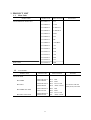
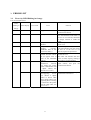
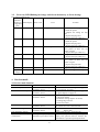
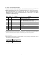
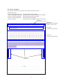
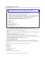
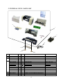
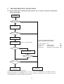
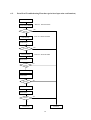
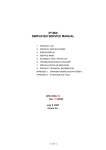
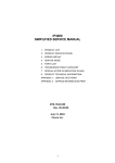
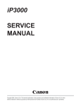
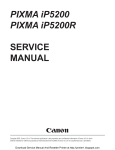
i450
SIMPLIFIED MANUAL
1
2
PRODUCT LIST
PRODUCT SPECIFICATIONS
3
4
5
6
7
ERROR CODE
SERVICE MODE
EXTERNAL VIEW / PARTS LIST
TROUBLESHOOTING FLOWCHART
SERVICE INFORMATION
QY8-1386-010
Rev 00
May 7, 2003
Canon Inc
1
1. PRODUCT LIST
1.1
Main Units
Product name
Canon Bubble Jet Printer i450
PIXUS 450i
1.2
Product code
Sales territories
8517A001AA
US
8517A002AA
CAN
8517A003AA
LAM LVT
8517A004AA
LAM HVT
8517A005AA
EUR
8517A006AA
DE
8517A007AA
FR
8517A008AA
ASA HVT
8517A009AA
AU
8517A010AA
KR
8517A011AA
GB
8517A013AA
TW
8517A014AA
HK
8517A015AA
CN
8517A012AA
JPN
Accessories
Consumables
Product name
Product code
Sales territories
BCI-24BK
6881A001AA to
6881A004AA
BCI-24CL
6882A001AA to
6882A004AA
001: JPN
002: EUR
003: USA / CAN
004: ASIA / AUST
BCI-24BK Twin Pack
6881A008AA to
6881A011AA
BCI-24CL Twin Pack
6882A008AA to
6882A011AA
Remarks
Canon Ink Tank
2
008: JPN
009: EUR
010: USA / CAN
011: ASIA / AUST
In common with the
S300, S330, and i320
2. SPECIFICATIONS
2.1.
Printer Specifications
Type
Paper feeding
method
Resolution
Throughput
(Target value)
Printing direction
Print width
Line feed speed
Interface
ASF stacking
capacity
Paper weight
Detection
functions
Acoustic noise
Environmental
requirements
Power supply
External
dimensions
Weight
Related standards
Serial number
location
Remaining ink
amount detection
Print head
alignment
Desktop serial color bubble jet printer
Auto sheet feed (no manual feeding)
4,800 dpi x 1,200 dpi (Max.)
Draft
Standard
Black (New Black)
18 ppm
12 ppm
Color (New Color)
12 ppm
4.8 ppm
Bidirectional, uni-directional
Max. 203.2 mm (220.9 mm in borderless printing)
215.9 mm/s
USB 2.0 Full Speed
Plain paper (75 g/m2):
High
----0.8 ppm
Max. 10 mm (Approx. 100 sheets)
2
64 to 105 g/m
- Cover open
- Remaining ink amount (dot count)
- Waste ink amount
- Carriage position
45 dB (high quality mode)
During operation
Temperature
Humidity
Non operation
Temperature
Humidity
Input voltage
Frequency
AC 100 to 127 V
50/60 Hz
AC 220 to 240 V
50/60 Hz
- Presence of print head
- Paper out (Paper end sensor)
- Pick-up roller
- Head-to-paper distance
5C to 35C (41F to 95F)
10%RH to 90%RH (no condensation)
0C to 40C (32F to 104F)
5%RH to 95%RH (no condensation)
Power consumption
Standby
32W
2.5W
30W
2.6W
Approx. 393 (W) x 254 (D) x 202 (H) mm
Approx. 3.7 kg, not including print head and optional device
Electromagnetic radiance:
VCCI, FCC, IC, CE Mark, Taiwan EMC, Korea EMC, CCIB, C-tick, CCEE
Electrical safety:
Electrical Appliance and Material Control Law (DENTORI), UL, C-UL,
CB Report, GS, CE Mark, FIMKO, CCIB (EMC), AS, CCEE, PSB, Electrical
Safety Regulations of Korea, SASO
Environmental regulations:
Energy Star, Blue Angel, Environment label
On the carriage ribbon cable holder (visible when the front cover is open).
Available (by dot count. Reset by user operation. Enabled at default.)
Available (11 types)
3
2.2.
Print Head Specifications
Print heads
Type
4-color removable ink tanks, single head for black and color (YMC) ink tanks
Print head
BK:
Color:
Ink color
Pigment-based black, Dye-based cyan, magenta, yellow
Ink tank
BCI-24Black, BCI-24Color
Weight (Net)
Print head, 60g
Supply method
As a service part (not including ink tanks)
Part number
QY6-0047-000
Note:
320 nozzles in 2 vertical lines, 30 pl
256 nozzles in 2 vertical lines (128 nozzles each) per color, alternate
5 pl and 2 pl nozzles in line, horizontal zigzag nozzle allocation
This print head is usable only for the new models of i450 and i470D, and not
usable for the S300 or S330.
4
3. ERROR LIST
3.1.
Errors by LED Blinking in Orange
User recoverable errors
LED
blinking in
Panel display
Error Code
Error
2 times
301
1000
No paper.
3 times
302
1300
Paper jam.
6 times
402
1401
Solution
orange
Set the paper, and press the
Resume/Cancel button.
Remove the jammed paper, and
press the Resume/Cancel button. If
the error is not resolved, check that
no foreign material is inside the
printer.
Install the print head, and close the
access cover.
Re-install the print head, or with the
print head installed, turn the printer
off and on. If the error is not
resolved, replace the print head.
Pressing the Resume/Cancel button
will exit the error.
(The waste ink absorber full error
occurs at 100% capacity, making it
impossible to perform printing.
Disconnect the USB cable to the
digital camera, and press the
Resume/Cancel button.
The print head is not
installed.
7 times
403
1405
The print head is not
installed
properly.
(EEPROM data of the
print head is faulty.)
8 times
202
1700
Warning: The waste ink
absorber becomes almost
full (to approx. 95% to
100% of the maximum
capacity).
11 times
611
2001
Digital
camera
transmission
time-out
error (When the printer
cannot communicate with
a digital camera, the
time-out error occurs.)
612
2001
Digital
camera Disconnect the USB cable, and press
non-supporting
device the Resume/Cancel button.
error (When a digital
camera or device other
than a digital camera, not
supporting Direct Printing
is connected to the printer
with the USB cable, the
error occurs.)
*1:The error code is stored in the operator / service call history of the EEPROM information.
5
3.2.
Errors by LED Blinking in Orange and Green Alternately, or Lit in Orange
User unrecoverable errors
LED
alternate
blinking in Panel display
orange and
green
2 times
802
Error Code
5100
4 times
804
5C00
6 times
806
5400
7 times
807
5B00
8 times
808
5200
9 times
Lights in
orange
809
No display
6800
6800
Error
Solution
Carriage error
1. Check that no foreign material
is inside the printer.
2. Replace the timing slit strip
film.
3. Replace the purge unit.
4. Replace the logic board ass’y.
Purge unit error
1. Check that no foreign material
is inside the printer.
2. Replace the purge unit.
3. Replace the logic board ass’y.
Internal temperature error
1. Turn the printer off, and after a
short period of time, turn the
printer on again.
2. Replace the logic board ass’y.
Waste ink absorber full error 1. Replace the ink absorber.
2. Replace the logic board ass’y.
Print head temperature rise 1. Turn the printer off, and after a
error
short period of time, turn the
printer on again.
2. Replace the print head.
3. Replace the logic board ass’y.
EEPROM error
Replace the logic board ass’y.
RAM error
Replace the logic board ass’y.
*1:The error code is stored in the operator / service call history of the EEPROM information.
4. Service mode
4.1 Service mode function
Function
Service test print
Procedures
Remarks
See “Service mode operation Set a sheet of A4/LTR- or larger-sized paper.
procedures” below.
For print sample, see page 9
EEPROM information print See “Service mode operation Set a sheet of A4/LTR- or larger-sized paper.
procedures” below.
For print sample, see page 10.
EEPROM initialization
See “Service mode operation The following items are not initialized:
procedures” below.
- USB serial number
- Destination settings (Japan / Overseas)
- Cleaning flag on arrival
- Waste ink counter
Waste ink counter reset
See “Service mode operation Both the main and the borderless print waste
procedures” below.
ink counters are reset at the same time.
Destination settings
See “Service mode operation Overseas: i450
procedures” below.
Japan:
PIXUS 450i
Print head deep cleaning
Cleans black and color, simultaneously.
Operation panel display See “Operation panel operation Confirm the operations of operation panel
confirmation
confirmation procedures” below. display and operation buttons. Perform the
confirmation at operation panel replacement.
6
4.2. Service mode operation procedures
1) Close the access cover, and turn off the printer. While pressing the Resume/Cancel button, press and
hold the Power button. (The LED lights in green to indicate that a function is selectable.)
2) While holding the Power button, release the Resume/Cancel button.
3) While holding the Power button, press the Resume/Cancel button 2 times, and then release the Power
and Resume/Cancel buttons. (In the operation panel, “02” will be displayed. Each time the
Resume/Cancel button is pressed, the LED lights alternately in either orange or green. During
initialization, the LED blinks in green.)
4) When the LED stops blinking and lights in green, press the Resume/Cancel button the specified number
of time(s) according to the function listed in the table below. (Each time the Resume/Cancel button is
pressed, the LED lights alternately in either orange or green.)
Time(s) LED
Function
Remarks
0 times Green
Power off
When the print head is not installed, the carriage returns
and locks in the home position.
1 time Orange Service test print
When the Power button is pressed during printing, printing
stops, and the mode returns to step 4) above.
2 times Green
EEPROM information print When the Power button is pressed during printing, printing
stops, and the mode returns to step 4) above.
3 times Orange EEPROM initialization
4 times Green
Waste ink counter resetting
5 times Orange Destination settings
Proceed to the following steps 5) and then 6) to set the
destination.
6 times Green
Print head deep cleaning
Cleans black and color, simultaneously.
7 times Orange Not used in servicing
8 times Green
Return to the menu selection Return to step 4) above.
or more
5) After the function (menu) is selected, press the Power button. The LED lights in green, and the selected
function is performed. (When the operation completes, the printer returns to step 4) above.)
<Destination setting>
6) Press the Resume/Cancel button the specified number of time(s) according to the destination listed in
the table below, and then the Power button.
Time(s)
LED
Destination
1 time
Orange
Overseas:
i450
2 times
Green
Japan:
PIXUS 450i
7
4.3. Service test print
After repair, print the service test print, and confirm the following items:
<Print quality items>
- Check 1, top of form accuracy:
- Check 2, EEPROM information:
- Check 3, nozzle check pattern:
- Check 4, vertical straight lines:
- Check 5, halftone:
The line shall be within the paper.
Destination and waste ink counter shall be checked.
Ink shall be ejected from all nozzles.
The lines shall not be broken.
There shall be no remarkable streaks or unevenness.
Check 1:
Top of form accuracy
Check 2:
EEPROM information
(Refer to page 1-13.)
Check3:
Nozzle check pattern
Check 4:
Vertical straight lines
Check 5:
Halftone
8
4.4. EEPROM information contents
On the EEPROM information print, the printer usage conditions can be confirmed. Refer to the sample
print given below.
1
2
3
4
5
6
7
8
9
10
11
12
PIXUS 470PDP=V1.00 Destination=02 D=004.8 Page=00562 CH=0002 Bk(00) Cl(00)
HeadT Bk=25.5 HeadT C=25.0 EnvT=30.0 FA=01 87 80 USB(1000AQ)
PC(M=0000 R=0000 T=0000 D=0000 C=0000) Bk=00000 C=00000 M=00000 Y=00000
ER(TIME=2002/10/21-21:48 ER0=5100 ER1=5C00 ER2=1000 ER3=1401)
TotalINK(Bk=00057098 C=00008108 M=00006992 Y=00007666)
CLTime=2002/10/15-15:36 PC(M=0028 R=0015 T=0000 D=0020 C=0009)
IC(Bk=1 C=1 M=1 Y=1) WP=0025 SetUsrReg=NONE
UR1(A:Bkeo=000 B:Ce0=000 C:Meo=000(Yeo=000) D:Lceo=000 E:Lmeo=000(Lyeo=000)
UR2(F:BkBi=000 G:ClBi=000 H:BkCl=000 I:LCBi=000 J:C_LC=000 K:M_LM=000)
ST=2002/9/15-20:15 PW(ON=0009 OFF=00005) BORDERLESS=00000
PAGE(ALL=00562 PP=00025 PC=0000 PR=00050 MP=0000 SP=0258)
CAMERA(BORDERLESS=0030 NORMAL=0028)
13
14
15
16
17
18
19
HDEEPROM
V0000
SN=0318-A43D
LN(04 05 01 06 00 00 03)
DI(Bk=+001 CL=+001)
IL=(Bk=-08 C=-08 M=-08 Y=-08)
WLA=-08 WLB=-08
NGBk=000 NGC=000 NGM=000 NGY=000
*1: The information surrounded by a blue border is printed in the service test print, also.
1 Model name, ROM version, destination, waste ink amount, number of pages printed, number of times
the head was installed, bi-directional registration (black, color)
2 Head temperature (black, color), internal temperature, process inspection information, USB serial
number
3 Number of times cleaning was performed (manual, deep cleaning, timer, dot count, head/ink tank
replacement), dot count of each color
4 Operator/ service call history (occurrence time*2, ER0, 1, 2, 3)
5 Total ink consumption (Bk=00000000mg, C=00000000mg, M=00000000mg, Y=00000000mg)
6 Cleaning time, number of times cleaning was performed (manual, deep cleaning, timer, dot count,
head/ink tank replacement), dot count of each color
7 Ink sponge recognition flag, number of times wiping was performed
8 User’s print head alignment values
9 User’s print head alignment values
10 Installation date, number of times printer was turned on/off, number of borderless printing pages
11 Number of pages fed (all, plain paper, postcard, Photo Paper Pro, Matte Photo Paper, Photo Paper Plus
Glossy)
12 Number of pages in Digital Camera Direct Printing (borderless, bordered)
HEAD EEPROM
13 Version
14 Serial number
15 Lot number
16 DI sensor adjustment value
17 Ink ejection level
18 Overlay level
19 Number of unusable nozzles (Bk, C, M, Y)
*2:
The time the user last performed printing before the error occurred.
9
*1
5. EXTERNAL VIEW / PARTS LIST
2
1
7
4
3
5
Key
Part Number
1
0023U60701
2
QM2-0485-000
3
QH3-3618-000
QH3-3619-000
4
WT3-5119-000
WT3-5120-000
WT3-5121-000
WT3-5123-000
WT3-5122-000
WT3-5131-000
WT3-5124-000
WT3-5158-000
WT3-5159-000
5
XB1-2300-607
6
XB4-7300-807
7
QY6-0047-000
Rank Q'ty
N
1
N
1
1
1
1
1
1
1
1
1
1
1
1
1
1
K
1
6
Description
WHOLE UNIT, W/O POWER SUPPLY UNIT
OUTPUT TRAY UNIT
AC Adapter:100-120V 50/60Hz
AC Adapter:220-240V 50/60Hz
CORD, POWER
CORD, POWER
CORD, POWER
CORD, POWER
CORD, POWER
CORD, POWER
CORD, POWER
CORD, POWER
CORD, POWER
SCREW,MACHINE,BIDING HEAD,M3x6
SCREW,TAP TIGHT,BIDING HEAD,M3x8
PRINT HEAD
10
Remark
PIXUS 450i
220V-240V
220V-240V (AU)
220V-240V (GB/HK)
100V-120V
100V-120V(JP)
100V-120V
220V-240V (CN)
220V-240V (LAM LV)
220V-240V (KR)
6.
TROUBLESHOOTING FLOWCHART
6.1. Printer Main Unit Troubleshooting Flowchart (how to printer operation confirmation
when refurbishing)
Power ON
Error displayed?
No
Yes
Open access cover,
Error displayed?
No
Yes
Connect to computer
< Service test pattern check items of >
(Refer to the attached print sample.)
Service test pattern
*Refer to 4. SERVICE MODE
1. Ink non-ejection:
2. Top margin:
3. Line:
4. Gray area:
Yes
Outside of paper
Not connected
White lines / uneven density
Correct?
No
Yes
Replace head and print
Correct?
No
Yes
Waste ink counter
No
Yes
Defective
Normal
< Note for normal printer refurbishment >
At the final step of refurbishment, be sure to reset the EEPROM in accordance with 4.
SERVICE MODE, the EEPROM reset procedure. Remove the print head, unplug the power
cord immediately, and do not print afterwards.
12
NG
NG
NG
NG
6.2.
Print Head Troubleshooting Flowchart (print head operation confirmation)
Connect to computer
*Refer to 4. SERVICE MODE
Nozzle check pattern
Yes
Correct?
No
Head cleaning
*Refer to 4. SERVICE MODE
Nozzle check
Yes
Correct?
No
Head refreshing
*Refer to 4. SERVICE MODE
Nozzle check
Yes
Correct?
No
Head refreshing
Nozzle check
Yes
Correct?
No
Replace ink tanks
Nozzle check
Yes
Correct?
No
Normal
Defective
13
7. Service Information
7.1 Whole Unit Replacement
When the unit is exchanged as a Whole Unit (WHOLE UNIT, W/O POWER SUPPLY UNIT:
0023U60701 <PIXUS 450i>, take the following procedures:
1.
2.
3.
4.
Remove the AC adapter from the printer returned from the user.
Install the removed AC adapter in the whole unit.
Perform destination setting. (Refer to “4. SERVICE MODE” for details.)
Power off the whole unit, and confirm that the printer ready for shipment (with the paper lifting plate
of the ASF in the upper position).
Caution:
For this printer model, as the Whole Unit for Japan has been designated as a service part, the product
name on the Whole Unit is a Japanese model name, PIXUS 450i. Consequently, when replacing the
Whole Unit in the regions other than Japan, replacement of the Output Tray Unit (QM2-0485-000), on
which “i450” is printed, is necessary.
14