1
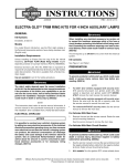
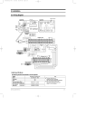
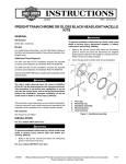
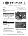
-J05758
REV. 2015-04-14
LED TAIL LAMP
GENERAL
2.
See Figure 1. Loosen the two screws (2) retaining the
tail/stop lamp assembly (1) to the lamp base (3). Pull the
lamp assembly away from the base.
3.
Push the locking tab (button), and disconnect the tail/stop
lamp connector [93B] (4) from the circuit board. Remove
the lamp from the vehicle.
Kit Numbers
67800355, 67800356, 67800357, 67800358, 67800614,
67800615, 67800616, 67800617
Models
For model fitment information, see the P&A Retail Catalog or
the Parts and Accessories section of www.harley-davidson.com
(English only).
is02969
1
4
2
Additional Parts Required
NOTE
This instruction sheet references service manual information.
A service manual for your model motorcycle is required for this
installation, and is available from a Harley-Davidson Dealer.
Kit Contents
See Figure 3 and Table 1.
3
INSTALLATION
For models WITH main fuse:
1.
2.
3.
4.
To prevent accidental vehicle start-up, which could cause
death or serious injury, remove main fuse before proceeding. (00251b)
1.
Tail/stop lamp assembly
Tail/stop lamp retaining screw (2)
Tail/stop lamp base
Tail/stop lamp connector [93B]
Figure 1. Removing the Tail/Stop Lamp Assembly
Refer to the owner's manual and follow the instructions to
remove the seat and main fuse. Retain all seat mounting
hardware.
is02970a
3
For models WITHOUT main fuse:
4
6
To prevent accidental vehicle start-up, which could cause
death or serious injury, disconnect negative (-) battery
cable before proceeding. (00048a)
7
1
2
NOTE
5
For 2004 and later XL (Sportster®) models, the negative battery
1.
2.
3.
4.
5.
6.
7.
cable is most easily disconnected at the engine crankcase.
1.
Refer to the owner's manual and follow instructions to
remove seat and disconnect negative (black) battery cable
from negative battery terminal. Retain all seat mounting
hardware.
NOTE
Figure 1 shows the original equipment tail/stop lamp mounted
to a full fender.
Figure 2. Socket Terminal Installation
4.
-J05758
Socket housing
Secondary lock
Locking tab (button)
Cavity
Socket terminal
Slot
Crimp tails
On the new tail/stop lamp assembly, the wires and socket
terminals are not installed in the four-way socket housing.
Many Harley-Davidson® Parts & Accessories are made of plastics and metals which can be recycled.
Please dispose of materials responsibly.
1 of 2
Refer to the original lamp removed in Step 3, and observe
which cavity contains which wires.
Apply a light coat of petroleum jelly or corrosion retardant
material to battery terminals.
The cavities are numbered on the face of the secondary
lock. The blue, red/yellow and black wires and terminals
must be installed into the same cavities in the socket
housing of the new lamp as follows:
Refer to the Owner's Manual, and follow the instructions
to install the seat.
a.
See Figure 2. On the secondary lock (2) side of the
socket housing (1), position the socket terminal (5)
with the slot (6) and crimp tails (7) facing up (in the
same direction as the button (3) on the top of the
socket housing).
b.
Insert the terminal into the correct cavity 1, 2, 3 or 4
(4) until it snaps into place with an audible "click".
c.
Gently tug on wire ends to verify that all terminals are
locked.
d.
Rotate the hinged secondary lock inward until tabs
fully engage latches on both sides of connector.
NOTES
If the terminal must be removed and reinstalled, refer to the
MULTILOCK ELECTRICAL CONNECTORS section of the
appropriate Service Manual.
After installing seat, pull upward on seat to be sure it is
locked in position. While riding, a loose seat can shift
causing loss of control, which could result in death or
serious injury. (00070b)
Be sure headlamp, tail and stop lamp and turn signals are
operating properly before riding. Poor visibility of rider to
other motorists can result in death or serious injury.
(00478b)
8.
Turn the ignition/ light key switch to ON, but do not start
motorcycle. Check operation of all lamps.
SERVICE PARTS
is08008
2
Fill pin cavities in the circuit board with dielectric grease from
the packet in the kit before assembling connector halves.
5.
1
Connect the socket housing on the new tail/stop lamp
assembly to the four-way pin housing in the circuit board.
3
NOTE
Do not over-tighten screws. Over-tightening the screws can
crack the tail/stop lamp lens or scratch the fender paint.
6.
Install the tail/stop lamp to the vehicle. Alternately tighten
the screws to 20-24 in-lbs (2.3-2.7 Nm).
4
NOTE
See Figure 1. Lamp assembly (1) attaches as shown on full
fender models.
Figure 3. Service Parts
Do not over-tighten bolts on battery terminals. Use
recommended torque values. Over-tightening battery terminal bolts could result in damage to battery terminals.
(00216a)
7.
Verify that the ignition/ light key switch is in the OFF position.
Models WITH main fuse: Refer to the Owner's Manual
and follow the instructions to install the main fuse.
Table 1. Service Parts Table
Item
Description
Part Number
1
Lens
Not sold separately
2
Tail lamp jumper harness
69200905
3
4-way socket housing
73154-96BK
4
5 gram package dielectric grease 76001-04
Models WITHOUT main fuse: Connect the negative
battery cable per the instructions in the Owner's Manual.
-J05758
2 of 2