1
ASSEMBLY AND MAINTENANCE INSTRUCTIONS - MULTI-ROTOR PUMP
Pumping Solutions
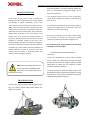
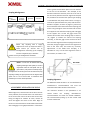
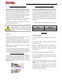
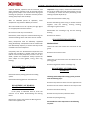
Coupling Misalignment:
PARALLEL
MISALIGNMEN
T
REGULAR ANGULAR
AND PARALLEL
MISALIGNMENT
ANGULAR
MISALIGNMEN
T
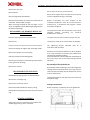
FLUCTUATION
OF EXTREMITIES
AERIAL VIEW
FRONT VIEW
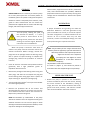
NOTE: Any coupling that is highly
subjected to stress by torque will have a
small reserve for stresses due to
misalignment. Conversely, if the coupling
receives a slight torque, it will have
ation is greater than 0.05mm place a shim on the foot
to the size of the deviation. "For example, if the
deviation observed is 0.25mm, then this is the size of
the shim to be placed on the foot. Tighten and repeat
the procedure for all other feet. Spacer-type coupling
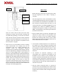
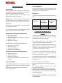
is used between the pump and the driver. To align it,
remove the spacer between the pump and the driver.
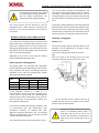
Produce a support, as shown in (Figure 7), which may
be connected to one of the halves of the coupling, and
which is long enough to reach the other half. Connect
this support to one half of the coupling and a dial gage
to the support arm so that the gage comes into
contact with the bar of the coupling half, as shown in
"A", (Figure 7). Rotate one half of the coupling
manually, so that the gage moves around the other
half. Once the alignment of the coupling bar has been
achieved, change the gage so that it leans against the
face of the same half, and make any necessary
adjustments. If the shafts have end-play, it is
advisable to carry out this face alignment check in
micrometers, as shown in "B".
greater reserve for misalignment conditions.
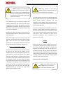
DIAL GAGE
NOTA: It must also be advised that any
coupling rotating at low speeds, as used in
conjunction with the low-speed side of a
gear reducer, may lead to relatively large
misalignments in the long term. On the other hand, any
coupling rotating at high speeds must be aligned with
great care so as to ensure that a continuous and
problem-free service will be provided.
ALIGNMENT OF SPACER COUPLING
Before alignment, check that the driver does not have
overly soft feet, to ensure that there is no undue stress
to the screws that secure the driver due to the base
being non-aligned or rotated. To check, remove all
shims and tighten the driver at the base. Begin to
loosen a screw and measure the deviation of that foot
with a dial gage or using depth indicators. “If the devi-
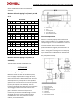
Coupling Alignment:
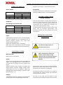
The Maximum radial variation in "A" should follow the
manufacturer's recommendation and must not
exceed the total radial variation of 0.127mm.
The maximum variation in the parallelism in "B"
should follow the coupling manufacturer's
recommendation and must not exceed 0.0762mm.
The recommended spacing up to the central shaft
must be maintained.