1
IMPORTANT SAFETY INSTRUCTIONS
When installing and operating this Product and other associated equipment, basic safety precautions should always be followed, including the
following:
1. Read and follow all instructions.
2. This Control Panel must be installed by a qualified electrician, according to the National Electrical Code (including article 680) or Canadian
electrical Code (including section 68) and, local code requirements. For Canadian installations, transformer supply circuit must be protected
by a ground fault circuit interrupter.
3. Install this control not less than 5 feet (3 meters in Canada) from inside edge of pool. USE COPPER CONDUCTORS ONLY.
4. Do not exceed the maximum ratings of individual components, wiring devices, and current carrying capacity of conductors.
5. For Control grounding, bonding, installing and the wiring of underwater lights, refer to Article 680 of the National Electrical Code or Article
68 of the Canadian Electrical Code.
6. The Control should not operate any equipment which would cause bodily injury or property damage should it be activated unexpectedly.
7. Do not connect two or more transformers in parallel or use with dimmers.
GUIDELINES FOR SECONDARY WIRE SIZE PER LENGTH
120 Volt Primary Input - 100 Watt Output
120 Volt Primary Input - 300 Watt Output
Distance* 2#6AWG 2#8AWG 2#10AWG 2#12AWG
Feet
5 Ft.
12V
12V
12V
12V
10 Ft.
12V
12V
12V
13V
20 Ft.
12V
12V
13V
13V
30 Ft.
12V
13V
13V
14V
40 Ft.
13V
13V
14V
50 Ft.
13V
13V
14V
60 Ft.
13V
14V
70 Ft.
13V
14V
80 Ft.
13V
14V
90 Ft.
14V
100 Ft.
14V
110 Ft.
14V
* Length of run to light from transformer.
Distance* 2#6AWG 2#8AWG 2#10AWG 2#12AWG 2#14AWG
Feet
5 Ft.
12V
12V
12V
12V
12V
30 Ft.
12V
12V
12V
13V
13V
60 Ft.
12V
12V
13V
13V
90 Ft.
12V
13V
13V
120 Ft.
13V
13V
150 Ft.
13V
13V
180 Ft.
13V
210 Ft.
13V
240 Ft.
13V
* Length of run to light from transformer.
READ, FOLLOW AND SAVE THIS INSTRUCTION MANUAL
INSTALLATION
9. The enclosure must be grounded as required by
NEC, Article 680 and any applicable local codes.
For Canadian installations, the transformer supply
circuit must be protected by a ground fault circuit
interrupter.
10. If this enclosure is used for direct connection of
underwater lights, refer to 1999 NEC 680-21(b),
2002 NEC 680-24(b) or CEC 68-060, 062 and 066
for further details.
11.Use the tables at the top of page 3 as a guide to
determine the correct secondary wire size.
12.Connect power supply to voltage tap (lead) on
primary side of transformer as noted in table. Make
sure that all unused transformer taps are separately
insulated.
13.Check voltage at lamp terminals after installation.
It should be 12+ 0.3 volts.
14.Install front panel over wiring compartment. The
control is now ready for programming, see
OPERATION section on Page 3.
1. Remove the four #10 hex head screws from the back
of the enclosure and attach mounting brackets to
enclosure.
2. Select the proper location for the Control Panel and
hang enclosure on a flat vertical surface or other
support, using hardware suitable for the purpose.
3. Prepare the necessary conduit runs, terminate
them at both ends and pull in the conductors as
specified by the installation layout.
*If this control is to be used for direct connection
to under-water lights, a Nonmetallic Hub Kit
shall be used. Order 156PA13713A for a 1/2” Kit,
156PA13714A for a 3/4” Kit or 156PA13715A
for a 1” Kit.
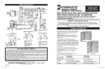
4. Refer to Figure 1 below; note that
this enclosure contains one Time
Switch. To wire the panel,
follow the wiring diagram located
inside the enclosure door. Make sure that
connections to time switch terminals are tight
(25 lb.-in. minimum) and insulation clears the
pressure plate - see illustration.
5. If required by the heater manufacturer, install
fireman switch kit 156T4042A (not furnished)
on Time Switch Plate and make the fireman
switch connections. Use at least #18 AWG
wiring with insulation rated 300 Volt or higher.
Place heater ON/OFF switch on heater to ON
(see Figure 2 on page 3). Some heaters may require
a special connecting harness, contact heater
manufacturer for details.
6. To install an additional wiring device inside the
enclosure, first remove rectangular knock-out in
dead front. Next, remove hex head screws in back of
enclosure and install stand-offs* in place of screws.
Attach wiring device to stand-offs.
*Stand-offs are not furnished. Order 21T156A for a set of four
7.
8.
OPERATION
THE FIREMAN SWITCH (Heater Protection Mechanism),
if required, is factory set and shuts OFF the heater 20
minutes before the Time Switch turns OFF the filter pump.
The Fireman Switch requires no setting or service.
TIME SWITCH OPERATING
INSTRUCTIONS
CLOCK
DIAL
TIME
POINTER
OFF
TRIPPER
MANUAL
LEVER
ON
TRIPPER
1. TO SET “ON” AND
“OFF” TIMES: Hold
TRIPPERS against edge
of CLOCK-DIAL, pointing
to time (AM or PM)
when ON and OFF operations
are desired. Tighten tripper
screws firmly.
2. TO SET TIME-OF-DAY:
Pull CLOCK-DIAL outward. Turn in either direction
and align the exact time-of-day on the CLOCK-DIAL
(the time now, when switch is being put into operation)
to the pointer.
• TO OPERATE SWITCH MANUALLY: Move
MANUAL LEVER below CLOCK-DIAL left or
right as indicated by arrows. This will not affect
the next operation.
• FOR MORE THAN ONE DAILY ON-OFF
OPERATION: Place additional tripper pairs on
CLOCK-DIAL (order 156T1978A).
• IN CASE OF POWER FAILURE: Reset CLOCK DIAL to proper time of day. See step 2 above.
Figure 2
TROUBLESHOOTING
(4) stand-offs and mounting hardware.
If external bonding is required, install a bonding lug
at bottom of enclosure and bond installation
according to code requirements.
Testing of the installation is optional and
recommended only if pump is securely in place
and will not be damaged by this test:
a. Turn the manual lever of the Time Switch to OFF.
b. Turn ON power at breaker panel.
c. Move the manual lever of Time Switch to the
right (ON).
Pump should start and run on full speed. In case of
unsatisfactory results, turn OFF power, check
your wiring, refer to Troubleshooting on Page 3.
TO SET FILTER PUMP TIME SWITCH, follow
instructions on the right. The length of the daily filtration/
heating cycle depends on many variables such as size, shape,
geographic location of the pool, water chemistry, type of
pool equipment, usage and season of year. If not sure,
contact your local pool service professional for advice.
Figure 1
2
SYMPTOM
CAUSE(S)
CORRECTIVE ACTION
1. Time Switch will not keep
time but dial is turning.
1a. Frequent power outages
1b. Wrong voltage/cycle
1c. Loose clock motor connections
Reset dial
Change clock motor
Check connections
2. Time Switch Dial stops
at ON or OFF tripper.
2a. Loose tripper
2b. Bent dial
2c. Defective motor
Check/change tripper
Check/change mechanism
Change clock motor
3. Dial stops after switch
turns OFF.
3a. LINE leads are connected
to LOAD terminals
Reverse LINE and LOAD connections
4. Load is ON at all times dial is turning.
4a. Welded contacts
4b. Two ON trippers and
no OFF tripper on dial
4c. Defective mechanism
Change mechanism
Change tripper
5a. Defective clock motor
(open coil due to lightning or surge)
5b. Loose clock motor connections
5c. Wrong voltage
Change clock motor
5. Dead clock motor. (Clock
motor gears do not rotate).
3
Change mechanism
Check connections
Change clock motor