1
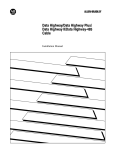
PLC Gateway
Planning, Installation,
and Service
PL02-500
Implementation
PLC Gateway
PLC Gateway
Planning, Installation,
and Service
PL02-500
Release 500
CE Compliant
5/01
Copyright, Trademarks, and Notices
© Copyright 1995 - 1997 by Honeywell Inc.
Revision 03 – May 22. 2001
While this information is presented in good faith and believed to be accurate,
Honeywell disclaims the implied warranties of merchantability and fitness for a
particular purpose and makes no express warranties except as may be stated
in its written agreement with and for its customer.
In no event is Honeywell liable to anyone for any indirect, special or
consequential damages. The information and specifications in this document
are subject to change without notice.
TotalPlant and TDC 3000 are U.S. registered tradmarks of Honeywell, Inc.
Other brand or product names are trademarks of their respective owners.
About This Publication
This publication is provided to guide the user in planning, installing, and servicing the
Programmable Logic Controller Gateway (PLCG). Only those components unique to the PLCG are
covered in detail. It is not intended to be a substitute for standard LCN Site Planning, System
Installation, and Service manuals, which are referenced for further detail.
This manual describes PLCI board 51400997-100 with Firmware Revision J and PLCG relay panel
51304421-100. Early-production relay panel 51304154-100 may be used in all applications except
Allen-Bradley protocol using redundant PLCGs.
This publication supports TotalPlant Solution (TPS) system network Release 500 and CE
Compliant hardware. TPS is the evolution of TDC 3000X.
Any equipment designated as “CE Compliant” complies with the European Union EMC and
Health and Safety Directives. All equipment shipping into European Union countries after January
1, 1996 requires this type of compliance—denoted by the “CE Mark.”
PLCG Planning, Installation, and Service
5/01
Standard Symbols
The following defines standard symbols used in this publication
Scope
ATTENTION
Notes inform the reader about information that is required, but not
immediately evident
CAUTION
Cautions tell the user that damage may occur to equipment if proper care is
not exercised
WARNING
Warnings tell the reader that potential personal harm or serious economic
loss may happen if instructions are not followed
OR
53893
53894
Ground connection to building safety ground
Ground stake for building safety ground
DANGER
SHOCK HAZARD
53895
Electrical Shock Hazard—can be lethal
DANGER
HIGH VOLTAGE
53896
Electrical Shock Hazard—can be lethal
53897
Rotating Fan—can cause personal injury
PLCG Planning, Installation, and Service
5/01
Table of Contents
1
INTRODUCTION
1.1
1.2
1.3
1.4
2
SITE PREPARATION
2.1
2.2
2.2.1
2.3
2.3.1
2.3.2
2.3.3
2.4
2.4.1
2.4.2
2.4.3
2.4.3.1
2.4.3.2
2.4.3.3
2.4.3.4
2.5
2.5.1
2.5.2
2.5.3
3
General Description
PLCG Module for CE
Honeywell Support Services
Related Publications
Storage Conditions
Site Requirements
Dimensions and Weight
Electrical Requirements
AC Voltage Options
Frequency
Current in Amperes at 120 Vac
Configurations
Nonredundant Configurations
Redundant Configurations
Limitations
Physical Limitations
Single vs Multidrop Cabling
Cable Lengths
Direct-Connection
PLCG to PLC Connections
Modem Usage and Selection
Nonredundant PLCG Port Connections
Redundant PLCG Port Connections
INSTALLATION
3.1
Unpacking
3.2
Assembly and Cabling
3.2.1
Module Installation
3.2.2
LCN Node Pinning
3.2.3
CLCN Node Pinning
3.2.4
CE Equipment Installation
3.2.5
PLCI Pinning
3.2.5.1
Ram Clear (J1)
3.2.5.2
Board Revision (TS1)
3.2.5.3
Baud Rate and Parity (TS2)
3.2.5.4
Program Options (TS3)
3.2.6
PLCG Relay Panel Pinning
3.2.7
PLCG Cabling
3.2.8
Port Cabling and Pinning for Modems Using Modbus Protocol
3.2.8.1
Modem Cable
3.2.8.2
Modem Wiring
3.2.8.3
Modem Pinning
3.2.9
Port Cabling for Direct Connection to Modbus Equipment
PLCG Planning, Installation, and Service
i
5/01
Table of Contents
3.2.10
Port Cabling for Equipment Using Allen-Bradley Protocol
3.2.10.1
Direct Connection to Allen-Bradley Controllers
3.2.10.2
Allen-Bradley CIM Pinning
3.3
Installation Wrap-Up
4
CHECKOUT
4.1
Power-On Tests
4.1.1
Electronics Checks
4.2
Startup
4.3
Communications and Performance Statistics
4.3.1
PLC Error and Retry Counters
4.3.2
Port Statistics
4.3.2.1
Subslots Processed Per Second
4.3.2.2
Number of Messages Transmitted/Second
4.3.2.3
Number of Messages Received/Second
4.3.2.4
Number of Bytes Transmitted/Second
4.3.2.5
Number of Bytes Received/Second
4.3.2.6
Number of Scan Buffer Misses/Second
4.3.2.7
Number of Keepalive Buffer Misses/Second
4.3.2.8
Number of Output Buffer Misses/Second
4.3.2.9
Firmware Freetime/Second Counters
4.3.2.10
Number of Processing Buffer Misses/Second
5
SERVICE
5.1
Overview
5.1.1
Module Configuration - Standard and CE Compliant PLCG
5.2
Field Adjustment
5.3
General Troubleshooting
5.4
PLCI Troubleshooting
5.4.1
PLCI Hardware Indicators
5.4.2
PLCI Hardware Indicator Troubleshooting Chart
5.4.3
PLCI System Software Indications
5.4.3.1
Battery Failure
5.4.3.2
Device Failure
5.4.3.3
Data Hiway Port Error Codes
5.5
Spare Parts
INDEX
PLCG Planning, Installation, and Service
ii
5/01
INTRODUCTION
Section 1
This section provides an overview of the PLCG equipment, and lists reference documents
available from Honeywell.
1.1 GENERAL DESCRIPTION
The Programmable Logic Controller Gateway provides a method of economically
connecting various Programmable Logic Controllers to your Honeywell TotalPlant
Solution (TPS) system.
This manual guides you through the planning and installation considerations unique to the
PLCG equipment. However, this manual is not intended to be a substitute for the LCN Site
Planning manual and LCN System Installation manual, listed in the standard LCN
publications referenced in subsection 1.3 of this manual.
The PLCG runs under an unmodified HG (Hiway Gateway) software personality. The
hardware is similar to HG hardware, contained in a standard TPS five-slot equipment
module that supports the Local Control Network (LCN). In the PLCG, the Data Hiway
Interface (DHIF) board and its I/O board are replaced with the Programmable Logic
Controller Interface (PLCI) board and its I/O board. A PLCG relay panel is installed on
the rear of the module.
A redundant PLCG pair is composed of two PLCG modules equipped as above, but
sharing one relay panel.
53678
Figure 1-1 — PLCG Nonredundant Dual Node Module (Front View)
PLCG Planning, Installation, and Service 1-1
5/01
1.2
1.2 PLCG MODULE FOR CE
The CE compliant PLCG and PLCI I/O cage supports the three styles of modules. It
supports the nonredundant PLCG, the redundant PLCG and the communications
redundant PLCG. The CE compliant modules are capable of holding both the older and
newer types of I/O board designs.
The I/O File has been modified to make electrical contact with face plates attached to the
I/O boards. This provides low impedance ground path for the cable shields. The face
plates and the wire mesh covering the fan openings also provides EMI shielding around
the module. The module is similar in all other respects.
CLCNA
PLCI I/O
CLCNB
16824
Figure 1-2 — CE Compliant PLCG Nonredundant Dual Node Module (Back View)
1.3 HONEYWELL SUPPORT SERVICES
Optional Installation Support, Field Services, and Technical Support are available during
the on-site installation and checkout of TPS system equipment. Honeywell representatives
are available to assist in interpreting this manual and to help resolve problems or situations
not covered by this manual. A toll-free number (800-822-7673; in Arizona, 602-8635558) is available for technical assistance.
PLCG Planning, Installation, and Service 1-2
5/01
1.4
1.4 RELATED PUBLICATIONS
Honeywell's standard documentation is included with the system. The following
publications apply to the TPS system and should be referred to as required and available:
Publication
Title
Publicatio
n Number
Binder
Title
Binder
Number
Local Control Network Planning
SW02-501
System Site
Planning - 1
3020-1
LCN System Installation
SW20-500
LCN Installation
3025
LCN System Checkout
SW20-510
LCN Installation
3025
Hiway Gateway Specification and
Technical Data
HG03-500
System Summary 2
3010-2
Five/Ten-Slot Module Service
LC13-500
LCN Service - 2
3060-2
Dual Node Module Service
LC13-510
LCN Service - 2
3060-2
Maintenance Test Operations
SW11-502
LCN Service - 1
3060-1
Test System Executive
SW13-510
LCN Service - 3
3060-3
Hardware Verification Test System
SW13-511
LCN Service - 3
3060-3
Core Module Test System
SW13-512
LCN Service - 3
3060-3
Maintenance Test Operations
SW11-502
LCN Service - 1
3060-1
Process Operations Manual
SW11-501
Operation/Process
Operations
3050
PLCG Specification & Technical Data
PL03-500
System Summary 2
3010-2
PLCG Control Functions
PL09-500
Implementation/PL
C Gateway
3080
PLCG Implementation Guidelines
PL12-500
Implementation/PL
C Gateway
3080
PLCG Parameter Reference
Dictionary
PL09-540
Implementation/PL
C Gateway
3080
PLCG Forms
PL88-500
Implementation/PL
C Gateway
3080
PLCG Planning, Installation, and Service 1-3
5/01
PLCG Planning, Installation, and Service 1-4
5/01
2
SITE PREPARATION
Section 2
This section provides the following information for the PLCG: Storage conditions, site
requirements, electrical requirements, and configuration information.
2.1 STORAGE CONDITIONS
If the PLCG is to be placed in storage, follow these environmental constraints:
Temperature
Humidity (RH)
Shock*
-35° – +70°C
10 – 80%, max wet bulb 20 – 30°C
3.0 g for 10 milliseconds
* When enclosed in the original shipping container.
Note that the temperature/relative humidity cannot be cycled such that moisture or
condensation occurs on the equipment—keep the rate of change less than 6% per hour.
These storage and shipping requirements are for one year duration only, provided the
equipment is properly packaged and contains an adequate amount of desiccant (moisture
removing agent).
2.2 SITE REQUIREMENTS
The PLCG is designed for a Class A General Industrial environment. It must be operated
in a temperature environment of 0° – 50°C (32° – 122°F). While operating, components
of this system are not designed to withstand greater vibration than 1g.
This equipment is intended for use in a controlled environment. Although TotalPlant
Solution (TPS) system equipment will operate at 0 – 50°C, Honeywell recommends a
normal environment of 25°C (77°F) with a relative humidity of 40 – 50% to realize
maximum life and enhanced reliability.
2.2.1 Dimensions and Weight
The approximate dimensions and weight for each PLCG 5-slot module are:
Height
Width
Depth
17 cm
48 cm
61 cm
(7")
(19")
(24")
Weight
PLCG Planning, Installation, and Service 2-1
21.5 kg (46 lb)
5/01
2.3
2.3 ELECTRICAL REQUIREMENTS
The customer selected ac power option is installed in the PLCG before shipment.
The inrush current to each electronics module is limited to 15 A @ 120 V, 30 A @240 V.
2.3.1 AC Voltage Options
120, 220, 240 Vac +10%, -15%
2.3.2 Frequency
47 Hz to 63 Hz
2.3.3 Current in Amperes at 120 Vac
Avg
True RMS
Peak
Wattage BTUs/hr
MP-PLCGN1—68000 based,
Nonredundant Module
typical
maximum
1.34
2.06
1.82
2.78
8.86
13.14
217.8
283.1
742.7
965.4
MP-PLCGR1—68000 based,
2 Redundant Modules
(Two modules required)
typical
maximum
2.68
4.12
3.64
5.56
17.72
26.28
435.6
566.2
1485.4
1930.8
MP-PLCGN3—68020 based,
Nonredundant Module
typical
maximum
0.939
1.45
1.27
1.94
6.99
10.35
152.5
198.3
520.0
676.2
MP-PLCGR3 —68020 based,
2 Redundant Modules
(Two modules required)
typical
maximum
1.878
2.90
2.54
3.88
13.98
20.70
305.0
396.6
1040.0
1352.4
PLCG Planning, Installation, and Service 2-2
5/01
2.4
2.4 CONFIGURATIONS
Various nonredundant and redundant configurations of the PLCG connected to PLCs of
different manufacture are available. Depending upon certain limitations, the PLCG may
communicate to the PLCs either through short-haul modems or by a direct-connection.
2.4.1 Nonredundant Configurations
Figure 2-1 shows a PLCG connected in a nonredundant 5-slot module configuration.
Connections for a dual node module configuration are the same, but the PLCG relay panel
is mounted horizontally on the rear of the module. Each PLC port (PORT 1 and PORT 2 in
the figure) may service any number of individual Programmable Logic Controllers up to a
Honeywell-supported total of 16 PLCs per PLCG. See subsection 2.5.2 for examples of
nonredundant port cabling configurations.
NOT USED
5
J2
PLCI I/O
REDUNDANT
A-B
4
OTHERS
3
LCN-A
LCN-B
J2A
LCN I/O
2
PLCG
L
J2B
PORT 1
1
NO
CONNECTION
RELAY PANEL
CG
LG
PORT 2
51304421-100
Cables to Programmable
Logic Controllers
Figure 2-1 — PLCG in a Nonredundant Configuration
3066
Each port may be configured to either the Modbus or Allen-Bradley (A-B) protocol. That
is, in the nonredundant configuration, you may have Port 1 connected to a Modbus and
Port 2 connected to A-B equipment, or both ports configured to the same bus type.
In all nonredundant configurations, the pinning header on the PLCG relay panel must be
plugged into the OTHERS socket on the relay panel. Newer relay panels have this header
labeled as NORMAL CONFIG. See subsection 3.2.6 and Figure 3-7 for a more detailed
illustration of the pinning sockets and header.
PLCG Planning, Installation, and Service 2-3
5/01
2.4.2
2.4.2 Redundant Configurations
Figure 2-2 shows two PLCG 5-slot modules connected in a redundant configuration. This
configuration also supports up to a total of 16 PLCs. Notice only one PLCG Relay Panel
is used. In this configuration, the PLCG electronics within the modules are redundant with
the relay panel the only nonredundant part of the system. Again, connections for a dual
node module configuration are the same; the single relay panel is mounted horizontally. To
reduce the possibility of failure of the relay panel, the relay used is a special, high-reliability
device. See subsection 2.5.3 for examples of redundant port cabling configurations.
Primary PLCG
5
NOT USED
PLCI I/O
REDUNDANT
A-B
4
OTHERS
3
LCN-A
Secondary PLCG
LCN-B
LCN I/O
J2A
PORT 1
1
PLCG RELAY PANEL
LG
PLCI I/O
NOT USED
PORT 2
51304421-100
CG
5
L
J2B
2
4
3
LCN-A
LCN-B
LCN I/O
2
1
CG
LG
L
Figure 2-2 — PLCG Modules in a Redundant Configuration
Cables to Programmable
Logic Controllers
3062
If you use Modbus protocol in the redundant configuration, both ports (Port 1 and Port 2)
must be connected to Modbus compatible equipment. The configuration is again capable
of serving up to 16 PLCs through both ports. The pinning header on the PLCG relay panel
must be plugged into the OTHERS socket. Newer relay panels have this header labeled as
NORMAL CONFIG. See subsection 3.2.6 and Figure 3-7 for a more detailed illustration of
the pinning sockets and header.
PLCG Planning, Installation, and Service 2-4
5/01
2.4.3
If you use A-B protocol in a redundant configuration, only Port 1 may be used. You must
plug the pinning header on the PLCG relay panel into the REDUNDANT A-B socket and be
sure no cable is connected to Port 2. This configuration is capable of serving up to 16
PLCs through Port 1 through an Allen-Bradley communications controller. See subsection
3.2.6 and Figure 3-7 for a more detailed illustration of the pinning sockets and header.
NOTE
Ports 1 and 2 are independent ports in either nonredundant or redundant configurations
and, as such, cannot support the same tag names on different ports. For this reason,
PLCG redundancy applies to the electronics modules within the TPS equipment and
cannot be configured to provide PLC Network Cable redundancy.
2.4.3 Limitations
There are certain limitations and several options which must be considered in planning
your installation.
2.4.3.1 Physical Limitations
In a redundant application, the primary and secondary PLCG modules generally mount in
the same rack, or in the same dual node module. They are normally installed close to each
other because the interconnect cable (between primary and secondary PLCGs) is only 2
meters long.
If you have a specific reason for separating the PLCG modules further, thereby substituting
a longer interconnect cable, you must reduce the cable-length of each cable connected to
Port 1 and Port 2 by the same amount that you have increased the length of the interconnect
cable. Obviously, the length of a substitute interconnect cable must be less than 15 meters.
If your system uses a relay panel, the standard cable length to secondary PLCG is 2m, but
alternate cable lengths are available. However, if a longer relay panel cable is used, the
amount added to the relay panel cable must be subtracted from each of the Port 1 and Port
2 cables. Obviously, the length of a substitute relay panel cable must be less than 15
meters (50 feet).
PLCG Planning, Installation, and Service 2-5
5/01
2.4.3
2.4.3.2 Single vs Multidrop Cabling
There must be only a single cable from a port to the PLC, modem, or communications
controller that port is to service.
If you want to use a Modbus protocol multidrop arrangement, you must place a local
modem at the PLCG with remote modems connected to each of the PLCs in the network.
Allen-Bradley (A-B) protocol multidrop arrangements always connect through an AllenBradley communications controller (a CIM for Communications Interface Module). Since
this communications controller supplies the multidrop connections, only a single cable is
needed from the PLCG port to the A-B controller.
2.4.3.3 Cable Lengths
The cables from the PLCG ports cannot be longer than 15 cable-meters (50 cable-feet). If
the distance to a PLC or communications controller exceeds this limit, you must use shorthaul modems. See subsection 2.5 for modem considerations.
2.4.3.4 Direct-Connection
If you are connecting a single PLC (or an A-B communications controller) to one of the
ports, and the cable-length from the PLCG to the PLC is less than 15 cable-meters, you
may use an EIA-232 direct-connection (no modems).
In this arrangement, the EIA-232 cable supplied by Honeywell must be specifically wired
to a connector which mates your PLC. Subsections 3.2.7 and 3.2.8 show cable wiring
schemes for several types of PLCs and interface devices.
PLCG Planning, Installation, and Service 2-6
5/01
2.5
2.5 PLCG TO PLC CONNECTIONS
2.5.1 Modem Usage and Selection
Direct-connection, short-haul modems (sometimes called line-driver), or signal converter
devices can be used with the PLCG. As mentioned earlier, direct-connection is limited to a
maximum of 15 cable-meters between PLCI I/O or Relay card.
Signal converters are devices that convert signals between EIA-232 an EIA-422 or -485,
and are commonly used to provide extended distance or multidrop configurations.
A short-haul modem presents an EIA-232 hardware interface to the PLCG or PLC similar
to that presented by conventional telephone modems. The short-haul modem, however,
uses dedicated lines (not telephone lines) and may take liberties with interface protocol that
would not be acceptable in conventional telephone modem communications.
Conventional telephone modems are not typically used with the PLCG because they
severely limit bandwidth, and their necessary low speeds (baud rate) might degrade PLCG
performance. The PLCG also does not support the handshake signals commonly required
for modems, including Request-To-Send (RTS), Clear-To-Send (CTS), Carrier Detect
(CD), Data Set Ready (DSR), and Data Terminal Ready (DTR).
Various device and cable configurations are feasible. Consult with a communication link
specialist or vendors for devices and cabling appropriate to your application.
PLCG Planning, Installation, and Service 2-7
5/01
2.5.2
2.5.2 Nonredundant PLCG Port Connections
Figure 2-3 (A) and (B) illustrate examples of directly connecting PLCs to a nonredundant
PLCG. A maximum of only two PLCs may be connected in this manner.
Notice the cables can be no longer than 15 meters. Also note the cables must be wired so
that both the PLCG and the PLCs “think” they are connected to a modem. Details of this
cross-wiring will be covered in subsections 3.2.7 and 3.2.8.
(A) Direct Connect Usage — Modbus
(B) Direct Connect Usage — Allen-Bradley
Port 1
CIM
Port 1
PLC
PLC
Port 2
Port 2
PLC
On some A-B equipment each PLC supports
EIA-232 by including the CIM within the PLC.
The DF-1 Protocol must be used.
Note: When wired direct-connect, each port serves a single PLC.
(C) Modem Usage — Modbus
Standard EIA-232
cables ≤ 15 meters
Full-duplex twisted pair or other
cable suitable for modem use
Port 1
PLC
EIA-232 cables wired
for A-B equipment
PLCG
CIM
PLCG
Cross-wired EIA-232
Cables ≤ 15 meters
MODEM
Single PLC
PLC
MODEM
PLCG
MODEM
PLC
MODEM
Port 2
Standard EIA-232
cables ≤ 15 meters
MODEM
PLC
MODEM
Three multidrop
PLCs shown
PLC
(D) Modem Usage — Allen-Bradley
EIA-232 cables wired for A-B equipment
Port 1
CIM
CIM
Single PLC
PLC
A-B Data Hiways
PLCG
CIM
CIM
PLC
Port 2
EIA-232 cables wired for A-B equipment
CIM
PLC
Three multidrop
PLCs shown
CIM = Allen-Bradley
Communication Interface Module
CIM
Note: In all nonredundant configurations, one port may
support ModBus while the other port uses A-B
protocol provided the cables are wired to match
the equipment.
PLC
Note: Both ports of a PLCG support a total of 16 PLCs.
3103-A
Figure 2-3 — Typical Nonredundant PLCG Port Connections
PLCG Planning, Installation, and Service 2-8
5/01
2.5.3
Allen-Bradley includes their CIM (Communications Interface Module) inside some PLC
models, allowing the “direct” connection shown in (B). See Section 3 for detailed wiring
of this cable.
Figure 2-3 (C) and (D) illustrate examples of modem usage from a nonredundant PLCG.
The modems used in illustration (C) are the short-haul modems previously discussed. The
single PLC connected via two modems to Port 1 illustrate a maximum-length
configuration which will service a PLC at the greatest distance from the PLCG.
The multidrop PLCs connected to Port 2 in illustration (C) show a typical “network” of
PLCs using the Modbus protocol. These drops are connected half-duplex with the “local”
modem connected to the PLCG and “remote” modems connected to the PLCs. The local
is a “master” which commands each remote to respond at a specific time. Additional
loading caused by several modems on the network may reduce the overall length of the
network twisted pair cable; consult the manuals for your modem for particulars.
Illustration (D) shows Allen-Bradley equipment connected in similar arrangements to
illustration (C). Allen-Bradley protocol is full-duplex; that is, any PLC or the PLCG may
“talk” at any time. Allen-Bradley requires use of their own CIMs which interface their
own Data Hiway. Refer to subsection 3.2.8 and your Allen-Bradley manuals for specifics.
2.5.3 Redundant PLCG Port Connections
Figure 2-4 (A) and (B) illustrate examples of direct-connection to PLCs from a redundant
PLCG. Note there can be only two PLCs connected in this manner if you are using
Modbus protocol or only one PLC if you are using the Allen-Bradley protocol.
Port 2 cannot be used with Allen-Bradley protocol because the protocol is full-duplex and
messages may be sent and received simultaneously. The redundant PLCG firmware uses
that port to “listen” to outgoing messages while Port 1 is receiving messages. Modbus
protocol is half-duplex and messages are not sent and received simultaneously.
PLCG Planning, Installation, and Service 2-9
5/01
2.5.3
Notice Figure 2-4 (C) and (D) are very similar to those illustrations in Figure 2-3. AllenBradley full-duplex operation prevents Port 2 from being used, but there is little loss of
capability since up to 16 PLCs may be connected to the same network.
(A) Direct Connect Usage — Modbus
(B) Direct Connect Usage — Allen-Bradley
PLCG
PLCG
PLC
CIM
EIA-232 cables wired for A-B equipment
Port 1
Port 1
PLC
Cross-wired EIA-232
Cables ≤ 15 meters
PLCG
PLC
Do not use port 2
PLCG
Port 2
On some A-B equipment each PLC
supports EIA-232 by including the CIM
within the PLC. The DF-1 Protocol must
be used.
Note: When wired direct-connect, each port serves a single PLC.
(C) Modem Usage — Modbus
Port 1
MODEM
PLCG
PLCG
Standard EIA-232 cables ≤ 15 meters
Single PLC
Full-duplex twisted pair or other
cable suitable for modem use
PLC
MODEM
MODEM
MODEM
Port 2
MODEM
PLC
PLC
MODEM
Three multidrop
PLCs shown
PLC
(D) Modem Usage — Allen-Bradley
EIA-232 cables wired for A-B equipment
EIA-232 cables wired for A-B equipment
A-B Data Hiways
PLCG
PLCG
CIM
CIM
Port 1
Do not
use port 2
CIM
PLC
PLC
Three multidrop
PLCs shown
(Maximum = 16)
EIA-232 cables wired for A-B equipment
CIM
CIM = Allen-Bradley
Communication Interface Module
PLC
3104-A
Figure 2-4 — Typical Redundant PLCG Port Connections
PLCG Planning, Installation, and Service 2-10
5/01
3
INSTALLATION
Section 3
This section provides information for unpacking and assembling the PLCG.
3.1 UNPACKING
When the equipment arrives at the system site, open each shipping box, remove the protective
wrapping and carefully inspect each piece for any physical damage. If damaged, immediately
notify the carrier and your Honeywell sales representative as to the extent and type of damage.
Also check each piece of equipment against the invoice list for any missing items.
3.2 ASSEMBLY AND CABLING
Refer to Figure 2-1 for an illustration of a nonredundant PLCG installation. Note the
PLCG relay panel located on the rear of the module.
Refer to Figure 2-2 for an illustration of a redundant PLCG installation. Note that only one
PLCG relay panel is mounted on the primary PLCG.
NOTE
Some assembly and cabling of this equipment may have been done at the factory. If
so, please check your equipment and verify its installation is similar to that described.
3.2.1 Module Installation
If you are installing a redundant PLCG pair, you have two PLCG modules. Install the
primary PLCG module first.
1. Remove the primary PLCG module (with relay panel) from its shipping carton.
2. Securely fasten the PLCG module to its rack-mount with the hardware provided.
3. Connect ground straps or leads from the base of the cabinet (or a nearby module) to the
appropriate chassis-ground and logic-ground connections on the rear of the PLCG module.
Refer to the LCN System Installation manual for further grounding information.
4. Insure the power switch on the front of the PLCG module is off. Install the module power
cord supplied. Refer to LCN System Installation manual for power wiring information.
If this is a redundant installation, repeat steps 1 through 4 on the secondary PLCG module.
PLCG Planning, Installation, and Service 3-1
5/01
3.2.2
3.2.2 LCN Node Pinning
By convention, the node address for a nonredundant PLCG is even. The node addresses
for a redundant pair is even for the primary PLCG and numerically one higher (odd) for
the secondary PLCG.
LCN ADDRESS
If you are installing a nonredundant PLCG, perform the following steps on the PLCG
module. If this is a redundant PLCG installation, perform these steps twice, using a node
address on the secondary PLCG one higher from that of the primary PLCG.
LCN I/O BOARD
FROM REAR SLOT 2
51107403-100
P
Binary
Weight
Parity
6
64
5
32
4
16
3
8
2
4
1
2
0
1
Jumper Removed = "1"
Overall number of jumpers
cut, including the parity
jumper, must be an odd
number. This example
indicates node address
03.
NOTE: THE SOFTWARE WILL ALLOW ONLY
NODE ADDRESSES 1-64 AT THIS TIME
Figure 3-1 — LCN I/O Board, Address Jumpers
PLCG Planning, Installation, and Service 3-2
2923
5/01
3.2.3
3.2.3 CLCN Node Pinning
By convention, the node address for a nonredundant PLCG is even. The node addresses
for a redundant pair is even for the primary PLCG and numerically one higher (odd) for
the secondary PLCG.
8
P
7
6
6
5
5
4
4
ASSY NO. 51305072-100
REV A
3
3
BAR CODE
If you are installing a nonredundant PLCG, perform the following steps on the PLCG
module. If this is a redundant PLCG installation, perform these steps twice, using a node
address on the secondary PLCG one higher from that of the primary PLCG.
LCN A
J2
LCN B
1
J1
ON
2
2
1
0
1
0
LCN
Address
53392
Figure 3-2 — LCN I/O Board, Address Jumpers
1. Remove the LCN I/O paddleboard from rear slot 2 in the PLCG module. Refer to
Figure 3-2 for instructions and the location of the pinning header on the LCN I/O
board. Pin the node address as shown. Be sure to adjust the parity jumper as
required.
2. Reinstall the LCN I/O paddleboard.
PLCG Planning, Installation, and Service 3-3
5/01
3.2.4
3.2.4 CE Equipment Installation
The I/O board interfaces both LCN cable A and cable B to the KxLCN board or LLCN in a
Dual Node Module. New I/O boards and inteface cabling was developed to support the
CE community standards. Figures 3-3 through 3-5 illustrate the CE Compliant hardware.
TERM 1
TERM 2
LCN A
LCN B
53377
8
7
6
5 6
4
5
4
3
2
1
1
3
LCN A
0
ON
J1
2
BAR CODE
ASSY NO.
51305072-200
REV A
P
Figure 3-3 — CLCN A/B Faceplate
J2
LCN B
53368-A
Figure 3-4 — CLCNA I/O Board
PLCG Planning, Installation, and Service 3-4
5/01
LCN A
5
4
3
2
1
0
2
8
7
6
5
J1
1
ON
3
4
BAR CODE
ASSY NO.
51305072-300
REV A
6 P
3.2.4
J2
LCN B
53392-B
Figure 3-5 — CLCNA I/O Address Pinning
PLCG Planning, Installation, and Service 3-5
5/01
3.2.5
3.2.5 PLCI Pinning
Refer to Figure 3-6 to locate the pinning headers and jumpers in the following steps. If
you are installing a redundant PLCG pair, both PLCI boards must be pinned the same way.
3.2.5.1 Ram Clear (J1)
Locate J1 and insure that a jumper is installed.
3.2.5.2 Board Revision (TS1)
Do not alter TS1, the Board Revision header.
3.2.5.3 Baud Rate and Parity (TS2)
The baud rate of the two serial interfaces serving Ports 1 and 2 are set-up with the jumpers
on TS2 (near right-center in Figure 3-6). See Table 3-1 (or the table on the PLCI board)
for the pinning information. Be sure the baud rate for a given port matches the PLC(s) it is
communicating with. The baud rates of the ports may be set at different speeds. Notice
Port 1 uses the higher-numbered pins.
The transmit and receive data parity for Ports 1 and 2 are set by jumpers 5 and 1,
respectively. To send and receive odd parity on a port, its respective jumper must be
shorted. Conversely, even parity is obtained by the jumper being open. Make sure the
parity of a port agrees with the parity sent and expected by the PLC(s) to which it is
connected.
Table 3-1 — Baud Rate Pinning on PLCI Board
BAUD
RATE
50
150
300
1200
2400
4800
9600*
19.2KB
PORT 2
PORT 1
PIN 2
PIN 3
PIN 4
PIN 6
PIN 7
PIN 8
OPEN
OPEN
OPEN
SHORT
SHORT
SHORT
SHORT
OPEN
OPEN
SHORT
SHORT
OPEN
OPEN
SHORT
SHORT
OPEN
SHORT
OPEN
SHORT
OPEN
SHORT
OPEN
SHORT
OPEN
OPEN
OPEN
OPEN
SHORT
SHORT
SHORT
SHORT
OPEN
OPEN
SHORT
SHORT
OPEN
OPEN
SHORT
SHORT
OPEN
SHORT
OPEN
SHORT
OPEN
SHORT
OPEN
SHORT
OPEN
*Honeywell factory setting is 9600 baud with odd parity
PLCG Planning, Installation, and Service 3-6
5/01
3.2.5
Board Revision
Socket - Do not change.
TS1
TS3
TS2
Program TS3 as follows:
PIN
8
7
6
5
4
3
2
1
DESCRIPTION
Program TS2 according to chart in lower
DESCRIPTION
Always
Shorted
right corner of board. All pins
Always Shorted
Always
Shorted
SHORTED = both ports at 9600 baud *
Always Shorted
Short
=
Enable
User
Outputs
with odd transmit/receive parity.
Short = Enable User Outputs *
Open
=
Disable
User
Outputs
Open = Disable User Outputs
Always
Shorted
Always
Shorted
Always
Open
Always Open
TS2 JUMPERS
Short
=
Max.
Data
Acquision
Short = Max.
Data
Acquision
* *
Open
= Reduced
Bandwidth
Open
= Reduced
Bandwidth
Short
=
Allow
PLCG
Output
to track
changes
to PLC
Ladder
Short = Allow PLCG Output
to track
changes
to PLC
Ladder
* *
Open
=
Don't
track
changes
to
PLC
Ladder
Open = Don't track changes to PLC Ladder
Short
= Redundant
operation
(must
be set
in both
PLCGs)
Short
= Redundant
operation
(must
be set
in both
PLCGs)
* *
Open
=
Non-Redundant
operation
Open = Nonredundant operation
RAM CLEAR Jumper
Do not change.
* = Honeywell factory setting
PLCI
J1
51400997-100
3063
Figure 3-6 — PLCI Pinning
3.2.5.4 Program Options (TS3)
Pin 1 If you are installing a redundant PLCG, leave pin 1 shorted (it must be shorted on the
PLCI board in both PLCGs). If you are installing a nonredundant PLCG, open pin 1.
Pin 2 This pin is only recognized in applications involving Modbus protocol. If you want
the PLCG to track changes to the digital outputs made by the PLC ladder logic,
leave pin 2 shorted. The PLCG will include the digital outputs in its periodic scan.
If you do not want changes in the ladder logic tracked, open this pin. Note that in
this mode, the Modbus digital outputs are scanned immediately after the emulated
DHP Enable Processing command. Thereafter, digital outputs are updated using
PLC write echo data.
PLCG Planning, Installation, and Service 3-7
5/01
3.2.6
Pin 3 If you want the PLCG to acquire data at the maximum rate, leave pin 3 shorted. If
you want the acquisition rate reduced, open this pin. Note that with this pin
shorted, data is double-buffered; when the pin is opened, one data buffer is
disabled. For slower PLC devices, open this pin to reduce data transfer rate.
Pin 4 Always leave this pin open.
Pin 5 Always leave this pin shorted.
Pin 6 If you want the PLC to receive user outputs via Analog outputs, Digital outputs,
and Timer/Counters, leave Pin 6 shorted. If you want to suppress user outputs to
the PLC, open Pin 6.
Pins 7 & 8—Always leave these pins shorted.
3.2.6 PLCG Relay Panel Pinning
Refer to Figure 3-7. If you are installing a nonredundant PLCG or if you are assembling a
redundant Modbus installation, check that the header on the relay panel is in the OTHERS
socket. Newer relay panels have this header labeled as NORMAL CONFIG.
If you are assembling a redundant Allen-Bradley installation, be sure the relay panel header
is in the REDUNDANT A-B socket.
NORMAL REDUNDANT
A-B
CONFIG
RY1
J2A
PORT 1
PLCG RELAY PANEL
RY2
L
J2B
PORT 2
51304421-100
CG
LG
Figure 3-7 — PLCG Relay Panel
PLCG Planning, Installation, and Service 3-8
3105-A
5/01
3.2.7
3.2.7 PLCG Cabling
1. Connect a 1-meter (3 ft.) cable (30731611-001) between J2A on the relay panel and J2
on the PLCI I/O board in same PLCG module. CE Compliant hardware uses a 3meter cable (51196074-100). Refer to Figure 2-1.
2. If you are using PLCI and PLCI I/O boards with the relay panel, connect a 1-meter
(3 ft.) cable (51201420-001) between J2A on the relay panel and J2 on the PLCI I/O
board at the rear of the module. Refer to Figure 2-2.
3. If this is a redundant Gateway installation using the relay panel, connect a 2-meter
(6 ft.) cable (51201420-002) between J2B on the relay panel and J2 on the PLCI I/O
board in the secondary module. Refer to Figure 2-3.
4. Be sure the two latches which secure each cable-end to its connector are fastened on all
of the cables.
3.2.8 Port Cabling and Pinning for Modems Using Modbus Protocol
NOTE
Two 51304514-100 field port cables, each without a plug on one end, have been
shipped with your PLCG. You must purchase and install the proper plugs to mate your
brand and model of equipment. This section will aid you in selecting and wiring those
plugs.
PLCG uses only the following signals:
Pin 1 = Shield (for electrical noise protection)
Pin 2 = Transmit Data (TXD) output from PLCG
Pin 3 = Receive Data (RXD) input to PLCG
Pin 7 = Logic Ground (GND)
PLCG does NOT support these EIA-232 handshake signals:
Request To Send (RTS)
Clear To Send (CTS)
Data Terminal Ready (DTR)
Data Set Ready (DSR)
Carrier Detect (CD) or Data Carrier Detect (DCD)
PLCG Planning, Installation, and Service 3-9
5/01
3.2.8
3.2.8.1 Modem Cable
For connection to a Modicon J478 modem or other short-haul modem serving a Modbus
port as illustrated in Figure 2-3 (C) or 2-4 (C), install a connector on the free-end of cable
51304514-100 using Figure 3-8 as a guide. Use a standard 25-pin male, D-Sub connector.
SHL
SHL
SHL
1
TXD
2
2
TXD
RXD
3
3
RXD
PLCG Port
RTS
1 or 2
4
4
RTS
CTS
5
5
CTS
25 Pin
Male D-Sub DSR
6
6
DSR
GND
7
7
GND
DCD
8
8
DCD
DTR
20
20
DTR
25 Pin
Male D-Sub
16815
Figure 3-8 — Cable for a Modem Serving Modbus Protocol
PLCG Planning, Installation, and Service 3-10
5/01
3.2.8
3.2.8.2 Modem Wiring
Use the instruction manual provided with your modems to install modem wiring between
all of the modems. Be sure the wiring meets the following criteria.
•
The multidrop modem “telephone lines” must be 4-wire, full-duplex with the linedriver of the local modem (PLCG end) in parallel with the line-receivers of all remote
modems (PLC ends). Likewise, the line-drivers of all remote modems are connected
to the line-receiver of the local modem.
•
A single pair of modems (point-to-point) must also be 4-wire, full-duplex with the
line-driver of each modem connected to the line-receiver of the other modem.
3.2.8.3 Modem Pinning
Use the instruction manual provided with your modems to properly pin your modems. Be
sure they meet the following criteria.
•
The local (PLCG end) modem must be pinned to hold its transmitter enabled at all
times, normally by putting RTS/CTS in the ON position.
The local modem must also be pinned to hold RXD in the marking state in the absence
of a valid carrier.
•
Each remote (PLC end) multidrop modem must be pinned to enable its transmitter
only when the PLC raises RTS.
All remote modems must also be pinned for an RTS/CTS delay of approximately 5 to
15 milliseconds. This delay can be determined empirically by the user, based upon the
hardware he has chosen. We have found the LD485A Black Box modems (Table 2-1)
operate satisfactorily using the 5 millisecond delay.
•
RTS/CTS delay need not be pinned in the local modem of a multidrop network, and is
also immaterial in a point-to-point arrangement.
PLCG Planning, Installation, and Service 3-11
5/01
3.2.9
3.2.9 Port Cabling for Direct Connection to Modbus Equipment
NOTE
Two 51304514-100 field port cables, each without a plug on one end, have been
shipped with your PLCG. You must purchase and install the proper plugs to mate your
brand and model of equipment. This section will aid you in selecting and wiring those
plugs.
If wiring information is not given here for your equipment, check with Honeywell’s
Multivendor Interface Program. If an MVI Program Test Report is available for that
equipment, cable wiring information will be given in that report.
For direct connection to Modbus protocol PLCs as illustrated in Figure 2-3 (A) or 2-4 (A),
use Table 3-2 to find the model number of the equipment you are using. From the table,
locate the Figure which will aid you in obtaining the proper connector, then install it on the
free-end of cable 51304514-100.
Table 3-2 — Modbus Protocol Cable Wiring Locator
PROGRAMMABLE CONTROLLER
MAKE AND MODEL
FIGURE
NUMBER
Honeywell
Honeywell 620 with
620-0043 CIM
Figure 3-9
Modicon
184 with J347 interface
Figure 3-9
Modicon
384 with J347 interface
Figure 3-9
Modicon
584
Figure 3-10
Modicon
884
Figure 3-9
Modicon
984
Figure 3-9
Triconex
4101 EICM
Figure 3-13
*
*This device employs the Modbus protocol but uses a cable identical
to one used for Allen-Bradley devices.
PLCG Planning, Installation, and Service 3-12
5/01
3.2.9
SHL
25 Pin
Male D-Sub
PLCG Port
1 or 2
SHL
SHL
1
TXD
2
RXD
3
RTS
4
4
CTS
5
5
DSR
6
6
GND
7
DCD
8
8
DTR 20
20
TXD*
3
RXD*
2
GND
25 Pin
Male D-Sub
7
* Transmit and receive data are "cross-wired" in a direct connection
16816
Figure 3-9 — Cable for Direct Connection to Modicon 884/984 and Others
SHL
SHL
SHL
1
TXD
2
TXD*
RXD
PLCG Port
RTS
1 or 2
CTS
25 Pin
Male D-Sub DSR
GND
3
RXD*
DCD
8
4
7
DTR 20
K
M
5
6
J
G
DSR
GND
DTR
L
P
Male
24 Pin Round
Connector
ITT Cannon
KPT06F-20-24P
or
Bendix
PT06E-20-24P (SR)
Z
* Transmit and receive data are "cross-wired" in a direct connection.
16817
Figure 3-10 — Cable for Direct Connection to Modicon 584
PLCG Planning, Installation, and Service 3-13
5/01
3.2.10
3.2.10 Port Cabling for Equipment Using Allen-Bradley Protocol
NOTE
Two 51304514-100 field port cables, each without a plug on one end, have been shipped
with your PLCG. You must purchase and install the proper plugs to mate your brand and
model of equipment. This section will aid you in selecting and wiring those plugs.
If wiring information is not given here for your equipment, check with Honeywell’s
Multivendor Interface Program. If an MVI Program Test Report is available for that
equipment, cable wiring information will be given in that report.
PLCG uses only the following signals:
Pin 1 = Shield (for electrical noise protection)
Pin 2 = Transmit Data (TXD) output from PLCG
Pin 3 = Receive Data (RXD) input to PLCG
Pin 7 = Logic Ground (GND)
PLCG does NOT support these EIA-232 handshake signals:
Request To Send (RTS)
Clear To Send (CTS)
Data Terminal Ready (DTR)
Data Set Ready (DSR)
Carrier Detect (CD) or Data Carrier Detect (DCD)
3.2.10.1 Direct Connection to Allen-Bradley Controllers
For connection to Allen-Bradley protocol PLCs as illustrated in Figure 2-3 (B) or (D) and
2-4 (B) or (D), use Table 3-3 to find the model number of the equipment you are using.
From the table, locate the figure which will aid you in obtaining the proper connector, then
install it on the free-end of cable 51304514-100.
Table 3-3 — Allen-Bradley Protocol Cable Wiring Locator
PROGRAMMABLE CONTROLLER
MAKE & MODEL
Allen-Bradley
Allen-Bradley
Allen-Bradley
Allen-Bradley
Allen-Bradley
Allen-Bradley
Allen-Bradley
Allen-Bradley
1770-KF2
1771-KE
1771-KF
1771-KG
1775-KA
1779-KFL
1779-KFLR
1785-KE
PLCG Planning, Installation, and Service 3-14
FIGURE
NUMBER
3-8
3-7
3-7
3-7
3-8
3-9
3-9
3-7
5/01
3.2.10
SHL
PLCG
Port
1 or 2
25 Pin
Male D-Sub
SHL
SHL
1
TXD
2
TXD*
3
RXD
3
RXD*
2
RTS
4
4
CTS
5
5
DSR
6
6
GND
7
DCD
8
8
DTR
20
11
GND
15 Pin
Male D-Sub
7
GND
13
* Transmit and receive data are "cross-wired" in a direct connection
16818
Figure 3-11 — Cable for Allen-Bradley 1771-KE, KF, KG and 1785-KE
SHL
PLCG Port
1 or 2
25 Pin
Male D-Sub
SHL
SHL
1
TXD
2
TXD*
RXD 3
RXD*
3
2
RTS
4
4
CTS
5
5
DSR 6
6
GND 7
DCD
GND
25 Pin
Female D-Sub
7
8
8
DTR 20
20
* Transmit and receive data are "cross-wired" in a direct connection
16819
Figure 3-12 — Cable for Allen-Bradley 1770-KF2 and 1775-KA
PLCG Planning, Installation, and Service 3-15
5/01
3.2.10
SHL
PLCG Port
1 or 2
SHL
SHL
1
TXD
2
TXD*
RXD 3
RXD*
3
2
RTS
4
4
CTS
5
5
DSR 6
GND
GND 7
DCD
25 Pin
Female D-Sub
7
8
DTR 20
* Transmit and receive data are "cross-wired" in a direct connection
16820
Figure 3-13 — Cable for Allen-Bradley 1779-KFL, KFLR and Triconex 4101 EICM
3.2.10.2 Allen-Bradley CIM Pinning
Methods for pinning CIMs vary between models. The parameters listed in Table 3-4 are
common to all PLCG/A-B configurations—use them as a guide.
Table 3-4 — Allen-Bradley Communications Interface Module Settings
PARAMETER
SETTING
BAUD RATE
Set the same as the PLCG field port. Do not set
above 9600 baud on the KF2. The KE/KF may be
set to 19.2 kbaud (see A-B manual).
PARITY
Match PLCI setting on TS2 header
BCC/CRC
BCC (Block Check Character)
HANDSHAKING
OFF
DH/DH+
As required by A-B devices
EIA-232/422
EIA-232
DIAGNOSTICS
Execute diagnostics locally (do not “pass-through”)
EMBEDDED RESPONSES
ON
DUPLICATE MESSAGE DETECT
ON
PLCG Planning, Installation, and Service 3-16
5/01
3.3
3.3 INSTALLATION WRAP-UP
Dress all cables neatly and out of the way to protect them from accidental damage. Plug all
modems and PLCG modules into their proper receptacles.
PLCG Planning, Installation, and Service 3-17
5/01
PLCG Planning, Installation, and Service 3-18
5/01
4
CHECKOUT
Section 4
This section tells you how to check the PLCG after it has been installed, plugged in and is
ready to go.
4.1 POWER-ON TESTS
You do not need to have the PLC equipment installed or connected to perform the checks
in this section. Do not, however, perform any of these tests until all other parts of the
PLCG have been installed according to Section 3.
4.1.1 Electronics Checks
Perform these electronics checks on the PLCG electronics module. If this is a redundant
PLCG installation, perform these checks on both PLCG modules.
1. Remove the front cover of the PLCG module. Before turning power on, ensure the
LO-NOM-HI jumper or switch on the front of the power supply is in the center or NOM
position.
2. Set the POWER switch to ON while observing the LEDs on the power supply, fan
assembly, and on the individual cards in the unit.
Note that the red LEDs on the boards light for a few seconds (it takes less than 30
seconds to complete the power-up tests), then they turn off and the green LEDs turn
on. If any red LEDs on the boards remain on, some portion of the power-up tests have
failed—record the alphanumeric status display code and proceed to Five/Ten-Slot
Module Service manual in the Service binder.
If the power-up test is successfully completed for all nodes, all green LEDs on all
boards are on (there may also be some yellow LEDs on or flashing), and the
alphanumeric status display indicates the node address you set in Section 3.2.2 of this
manual.
3. Check the power supply status LEDs (POWER OK and ERROR) and the FAN ALARM
LED. Note that the FAN ALARM and ERROR LEDs are off and the POWER OK LED
is on (it is a fault condition if both the ERROR and POWER OK LEDs are ON).
4. Press the momentary RESET switch. Note the power-up tests are initiated similar to
step 2, and the results are satisfactory.
5. Replace the front cover.
PLCG Planning, Installation, and Service 4-1
5/01
4.2
4.2 STARTUP
The PLCG software performs exactly like an HG (Hiway Gateway) and looks exactly like
an HG to the operator. To continue further, load the PLCG with the HG personality, use
PLCG configuration rules, and later use HG operations.
Configuration information is in the remaining publications in this binder. Loading and
operating procedures are in the Process Operations binder.
4.3 COMMUNICATIONS AND PERFORMANCE STATISTICS
To assist installation and on-going performance monitoring, the PLC Gateway provides
information about PLC communications and certain PLCG performance statistics. Once
per second the information is transferred to the database of each (on-scan) emulated DHP
making it available at the Universal Station via the System Maintenance Control Center
(SMCC). To prevent interference with off-line operations, statistical information is not
transferred to the database of an emulated DHP which is not enabled (on-scan). See
Figure 4-1.
DD MMM YY 08:45:30
SMCC MAIN MENU
MODULE MEMORY
HIWAY BOX MEMORY
PROBE FAILED MODULE
SYSTEM MAINT JOURNAL
ACTIVE MAINT JOURNAL
MODULE ERROR
REV/CONFIG STATUS
SECTOR INIT./REASSIGN
MAIN MENU
For Information On Funtions And Options Displayed On this Menu,
Position The Cursor On the Desired Target And Press HELP.
52271
Figure 4-1 — System Maintenance Control Center Main Menu Display
General information on use of the SMCC is in Maintenance Test Operations section of the
LCN Service -1 binder.
PLCG Planning, Installation, and Service 4-2
5/01
4.3
Selection of the HIWAY BOX MEMORY target of the SMCC’s Main Menu brings up a screen
requiring specific data to be filled-in. See Figure 4-2.
04 Sep 94 08:51:16 1
HIWAY BOX MEMORY
ENTER PARAMETERS ENTER
ENTER
ENTER
ENTER
ENTER
Hiway Number
Hiway Box Address
First Memory Address
Cyclic Update Interval
Change Detect
:
:
:
: OFF
OFF
:
(Decimal 1 To 20)
(Decimal 1 To 63)
(Octal)
(0 to 60 Seconds Or Off)
(ON-OFF)
For Information On Funtions And Options Displayed
On this Menu, Position The Cursor On the Desired Target
And Press HELP.
52272
Figure 4-2 — Hiway Box Memory Selection Display
Enter the correct Data Hiway number in the first "port." Add 32 (decimal) to the DHP box
number and enter the result in the next "port." Enter "1700" for the First Memory
Address. Also, enable "Cyclic Update Interval" and "Change Detect," if desired. Press the
Enter key to display the data. See Figure 4-3.
PLCG Planning, Installation, and Service 4-3
5/01
4.3
04 Jun 91 08:55:00
HIWAY BOX MEMORY DATA
CHANGE DETECT RESET
SPI
PRINT DATA
64 CONSECUTIVE WORDS ARE DISPLAYED STARTING WITH FIRST ADDRE
•
•
•
PRESS
PRESS
PRESS
0
1700
1710
1720
1730
1740
1750
1760
1770
000000
000000
000000
000000
000000
000000
000000
000000
MENU KEY TO RETURN TO MAIN MENU
PAGE FWD/PAGE BACK KEY TO ADVANCE OR BACKUP DATA S
ENTER KEY TO RE-DISPLAY SAME AREA (DEMAND UPDATE)
HIWAY NUMBER 05
HIWAY BOX ADDRESS 4
1
2
000000
000000
000000
000000
000000
000000
000000
000000
000000
000000
000000
000000
000000
000000
000000
000000
3
000000
000000
000144
000000
012131
000000
000000
000000
4
000000
000000
000000
000000
000000
000000
000000
153450
5
000000
000000
011621
000000
021316
000000
000000
000000
6
000000
000000
000000
000000
011621
000000
000000
020203
Error Counters
000000
000000
000000
000000
000000
000000
000000
000000
Retry Counters
Port 1 Statistics
Port 2 Statistics
Unused
Unused
For Information On Functions And Options Displayed On This Menu,
Position The Cursor On The Desired Target And Press HELP.
1. Each emulated DHP (hiway box address)
has its own Data Display.
2. Each memory word is 16 bits displayed as
6 digit octal.
0
1
2
170_
3
4
Retry Counters
172_
Subslots
# of Bytes
# of
# of
# of Bytes
Processed Messages Messages XMIT'D/Sec. Rec’d./Sec.
/Second XMIT'D/Sec. Rec’d./Sec.
7
# of Scan
# of
# of Output
Buffer
Keepalive
Buffer
Misses Buffer Misses Misses
Port 2 Statistics (same as line 1720 above
173_
Firmware Minimum
Freetime/1 Second
on Record
PLCI Firmware
Current Freetime
(Last Second)
Firmware Maximum
Freetime/1 Second
on Record
175_
Unused
176_
Unused
177_
6
Error Counters
171_
174_
5
Unused
Reserved for
Hiway
Security Word
Figure 4-3 — Hiway Box Memory Data Display
PLCG Planning, Installation, and Service 4-4
Unused
Number of
Processing
Buffer Misses
Firmware
Revision
Numbers
Unused
Unused
5563
5/01
4.3.1
4.3.1 PLC Error and Retry Counters
The PLCG maintains communications error counters (Memory addresses 1700-1707 = PLC
Index 1-8, respectively) and communications retry counters (1710-1717 = PLC Index 1-8,
respectively) for each configured physical PLC on each port. In each memory location, the 6
octal digits displayed represent two 8-bit counters. The upper 8 bits, 15 through 08, of each
memory word are for Port 1 and the lower bits, 07 through 00, are for Port 2. When a
communication error is detected between the PLCG and the physical PLC and retry is
permitted, the retry counter is incremented before the retry is performed. If retry is not
permitted or retry attempts have been unsuccessful, the error counter is incremented.
Once-a-second the counters’ results are transferred to the (enabled) DHP’s database. Since
the counters are kept by physical PLC, all logical PLCs (PC index values) referencing the
same physical PLC will show the same counter value. This is true even if the logical PLCs
(PC index values) are in different emulated DHPs. The counters are allowed to rollover after
reaching maximum value (16-bit counters at maximum displayed as 6 octal digits =
177777(8) = 65,535(10)) and are only reset when all emulated DHPs that reference a given
physical PLC are disabled (off-scan).
4.3.2 Port Statistics
Statistics for both ports are provided as an approximate measure of PLCG performance
4.3.2.1 Subslots Processed Per Second
Each time the PLCG processes a subslot (parameter) assigned to a given port, a 16-bit
counter is incremented and once-per-second the results are transferred to the emulated
DHP database. The counter provides a measured (versus calculated) value of the number
of subslots processed per second as seen by the PLCG. The number of subslots processed
during the last second before the transfer is then displayed in this location (1721/1731) for
the respective port.
NOTE
Although TDC 3000X system software treats a composite tag as a single data point, its
implementation requires the use of 2, 3, or 4 subslots in the PLCG. Since the PLCG
must collect the data for each subslot in use, PLCG performance must be measured and
compared in subslots (parameters) per second. If you wish to convert to TDC tags per
second from subslots per second, you must use a correction factor which expresses the
number of subslots per TDC tag. To calculate the correction factor, use the equation
below. If the system being measured contains any composite TDC tags, the correction
factor will have a value less than one.
overall TAG count
SUBSLOTS
X
TIME
TAGs
=
overall SUBSLOT count
TIME
6364
PLCG Planning, Installation, and Service 4-5
5/01
4.3.2
4.3.2.4.3.2.2 Number of Messages Transmitted/Second
This location (1721/1731) contains the number of complete messages transmitted through
this port in the previous 1- second period.
4.3.2.3 Number of Messages Received/Second
This location (1722/1732) contains the number of complete messages received through
this port in the previous 1- second period.
4.3.2.4 Number of Bytes Transmitted/Second
This location (1723/1733) contains the number of bytes transmitted through this port in the
previous 1- second period. It includes all control, header, trailer, and BCC/CRC bytes.
Multiplying this parameter by 11 (1 start bit + 8 data bits + 1 parity bit + 1 stop bit = 11) and
dividing by the port’s baud rate will yield an approximate indication of port utilization, on
transmit, as a fraction of the baud rate selected for this port (bandwidth used).
4.3.2.5 Number of Bytes Received/Second
This location (1724/1734) contains the number of bytes received through this port in the
previous 1- period. It includes all control, header, trailer, and BCC/CRC bytes. Multiplying
this parameter by 11 (1 start bit + 8 data bits + 1 parity bit + 1 stop bit = 11) and dividing by
the port’s baud rate will yield an approximate indication of port utilization on receive
(bandwidth used).
4.3.2.6 Number of Scan Buffer Misses/Second
This location (1725/1735) contains the number of times, in the previous second, that the
PLCG was ready to build a Data Request to a PLC on this port, but did not have a Scan
Buffer available. This value is typically nonzero, indicating that PLCG data acquisition is
running faster than the connected I/O subsystem network.
4.3.2.7 Number of Keepalive Buffer Misses/Second
This location (1726/1736) contains the number of times, in the previous second, that the
PLCG was ready to build a Keep Alive "refresh" message for this port, but did not have a
buffer available. This value is typically nonzero, indicating that PLCG Keep Alive writes are
running faster than the connected I/O subsystem network.
4.3.2.8 Number of Output Buffer Misses/Second
This location (1727/1737) contains the number of times, in the previous second, that the
PLCG was ready to build a User Output message for this port but did not have an Output
buffer available. This value is typically nonzero, indicating that PLCG output writes are
running faster than the connected I/O subsystem network.
PLCG Planning, Installation, and Service 4-6
5/01
4.3.2
4.3.2.9 Firmware Freetime/Second Counters
These three counters (1740-1741,1742-1743, 1744-1745) display approximations of PLCI
processor free time. The MINIMUM value indicates the least free time per second on
record, which equates to the heaviest loading. The MAXIMUM value indicates the most
free time per second on record, which equates to the lightest loading. The CURRENT value
indicates the free time during the previous 1- second period.
4.3.2.10 Number of Processing Buffer Misses/Second
This location (1746) contains the number of times, in the previous second, that the PLCG
was ready to process a requested PLC reply or unsolicited write (exception reporting) from
the PLC, but none was pending. When this location is nonzero, the PLCG is running faster
than the connected I/O subsystem network is transferring data.
PLCG Planning, Installation, and Service 4-7
5/01
PLCG Planning, Installation, and Service 4-8
5/01
5
SERVICE
Section 5
This section presents service instructions unique to the PLCG.
5.1 OVERVIEW
The Programmable Logic Controller Gateway (PLCG) is housed in a standard
TDC 3000X five-slot module, or in a newer (also standard) Dual Node Module. A PLCG
Relay Panel, a unique functional circuit board (PLCI), an input/output card (PLCI I/O), and
special cabling have been added to this standard module.
This manual provides instructions to test, troubleshoot, and repair those components
unique to the PLCG. Troubleshooting, disassembly, and assembly procedures for the
remaining five-slot module and its components are contained in the Five/Ten-Slot Module
Service or Dual Node Module Service manual in the LCN Service -1 binder.
The PLCG Relay Panel contains special high-quality, high-reliability components and is relatively
expensive. It is an ORU (Optimum Replaceable Unit) item and must be replaced if found faulty,
however, attempt to prove the relay panel has truly failed before replacing it indiscriminately.
Although cables are not considered ORU items, their part numbers are listed in subsection
5.5 for reference.
The following is the board complement for the 68000-based PLCG:
Slot
5
4
3
2
1
Front
PLCI
EMEM
EMEM
LCN
EMPU
P/N
51400997-100
51400910-100
51400910-100
51400667-100
51400901-100
Rear
PLCI I/O
P/N
51195096-100
LCN I/O
51107403-100
The following is the board complement for the 68020-based PLCG:
Slot
5
4
3
2
1
Front
PLCI
P/N
51400997-100
Rear
PLCI I/O
P/N
51195096-100
LLCN
HPK2-2
51401291-100
51401288-100
LCN I/O
51107403-100
The following is the board complement for an 2-slot node Dual Node Module-based PLCG:
Slot
2
1
Front
PLCI
K2LCN
P/N
51400997-100
51401288-100
PLCG Planning, Installation, and Service 5-1
Rear
PLCI I/O
KLCNA
P/N
51195096-100
51304542-100
5/01
5.2
The following is the board complement for a 3-slot node Dual Node Module-based PLCG:
Slot
3
2
1
Front
PLCI
P/N
51400997-100
Rear
PLCI I/O
P/N
51195096-100
K2LCN
51401288-100
KLCNB
51304544-100
One of the following PLCG Relay Panels is mounted on the rear of the PLCG module:
PLCG RELAY
PANEL
51304154-100
PLCG RELAY
PANEL
51304421-100
(Early custom production—can’t use
A-B protocol in redundant
configuration)
(Current Production-—required for the
Dual Node Module-based unit)
5.1.1 Module Configuration - Standard and CE Compliant PLCG
For module board configuration and part numbers, refer to the Five/Ten-Slot Module
Service or Dual Node Module Service manual.
5.2 FIELD ADJUSTMENT
There are no field adjustments for the PLCG. When replacing a board, you may have to
change some pins (or jumpers) on the board to make the board correspond with the
counterpart it is replacing. Do not alter pinning on a board revision socket—the revision
number might have changed on the newer board.
5.3 GENERAL TROUBLESHOOTING
Before investigating deeply into a problem, make some preliminary checks:
•
Is power applied to the module? Check switches, fuses, and circuit breakers on all
equipment to insure they are functioning.
WARNING
DO NOT REMOVE OR REPLACE CIRCUIT BOARDS WITH THE POWER ON.
Do not remove, handle, or transport circuit boards without observing proper Electrostatic
Discharge (ESD) procedures. To review ESD procedures, see the LCN Site Planning
manual
in the LCN Site Planning & Installation binder.
PLCG Planning, Installation, and Service 5-2
5/01
5.4
•
Note that the functional boards can be accessed through the front of each module by
removing the front cover. Inspect the confidence indicators on each processor board
and the EPLCI board. Check power supply and fan confidence indicators. Double
check the pinning on the EPLCI board (shown in subsection 3.2.3).
•
The PLCI I/O, KLCN_CA or KLCN_CB paddleboards are accessed from the rear of
the module.
To isolate a failed board, power supply, fan assembly, or other Optimum Replaceable Unit
(ORU), follow the service procedures provided in the Five/Ten-Slot Module Service
manual or the Dual Node Module Service manual in the LCN Service -1 binder.
5.4 PLCI TROUBLESHOOTING
The PLCI board has unique indicators on its front edge to offer confidence that the board is
working, and to provide assistance in case of a failure. The board also communicates with
the Universal Station to report software indications of hardware failures. This section
explains the function of these hardware/software indicators and will guide you in finding a
failure.
5.4.1 PLCI Hardware Indicators
(GRN)
PASS
MOD
TEST
(YELLOW)
(GRN)
PRI- 10 SEGMENT
DISPLAY
MARY
51400997-100
J1
PLCI
1
10
(RED) (RED)
BUS
SELF/
TEST TRANS
ERROR ERROR
Figure 5-1 — PLCI Test and Status Indicators
3106
There are four LEDs located on the front left edge of the PLCI board (see Figure 5-1).
Each LED’s definition and a brief description of its use follows. They are listed as shown
in the figure, from left to right.
PLCG Planning, Installation, and Service 5-3
5/01
5.4.1
SELF-TEST or BOARD FAILURE (Red)
This LED lights under the following conditions:
• Module power coming on
• Module or PLCI reset sequence working
• PLCI self-test in progress
• Self-test failed
• Local parity errors
This LED is extinguished under the following conditions:
• Self-test is completed successfully
• Module or PLCI reset sequence completed successfully
• PLCI Abort Command sequence completed
PASSED MODULE TEST (Green)
This LED is lighted after the PLCI successfully completes the CPU tests.
TRANSACTION ERROR (Red)
This LED lights under the following conditions:
• Module bus data parity error
• Bus error occurred during DMA access to module RAM
This LED is extinguished under the following conditions:
• Self-test is completed successfully
• Module power coming on
• Module or PLCI reset completed
• PLCI Abort Command in process
PRIMARY PLCI (Green)
This LED is lighted when the PLCI is on-line and functioning as the primary “HG.”
10-SEGMENT DISPLAY (Yellow)
Also, on the front edge of the PLCI board, there is a 10-Segment display composed of
yellow LEDs (see Figure 5-1). The function of each LED in this display, numbered 1 to
10 from left to right, are:
Segments 1, 2, and 3 monitor Field Port 1. Their functions are:
1. TX RTS—Illuminates when the transmit Request To Send is asserted.
2. RX DATA—Illuminates when Receive Data goes to a spacing condition.
3. DSR/CD—Illuminates when Data Set Ready and Carrier Detect are asserted.
Segments 4, 5, and 6 monitor Field Port 2. Their functions are:
4. TX RTS—Illuminates when the transmit Request To Send is asserted.
5 RX DATA—Illuminates when Receive Data goes to a spacing condition.
6. DSR/CD—Illuminates when Data Set Ready and Carrier Detect are asserted.
Segments 7, 8, and 9 are used at the factory. They have no use in field troubleshooting.
10. REDUNDANT PARTNER—Illuminates when the redundant partner is on-line.
PLCG Planning, Installation, and Service 5-4
5/01
5.4.2
5.4.2 PLCI Hardware Indicator Troubleshooting Chart
Use Table 5-1 to aid you in determining the cause of a failure detected by the two fault
indicators on the PLCI.
Table 5-1 — PLCI Hardware Indicator Troubleshooting Chart
INDICATION
SELF-TEST ON
after power-up or
reset sequence
SELF-TEST goes
OFF, then ON
after the HG
personality
has been loaded
POSSIBLE CAUSE
SOLUTION
Missing PLCI I/O Paddleboard
Install PLCI I/O Paddleboard in the
correct slot behind PLCI board.
Failed PLCI or PLCI I/O Board
Substitute known good boards.
Incorrect Software Release
Check that Software Release 200 or
later is being used.
Incorrect Configuration
Check that emulated Data Hiway
ports used are addresses 8 through
15.
Check that PLCGs are configured for
Hiway addresses 2 and 3.
Check that PLCG is configured to
perform the HTD functions.
Check for hardware configuration
errors; re-read Sections 2.4, 2.5, and
3.2 of this manual.
TRANSACTION
ERROR ON
Memory Board Error
Substitute known good memory
board(s).
If memory board(s) are OK, suspect
the PLCI itself.
PLCG Planning, Installation, and Service 5-5
5/01
5.4.3
5.4.3 PLCI System Software Indications
System software indications that indicate hardware failures are presented in the Hiway
Status display on the Universal Station (US). The Hiway Status display lists those brief
error statements and codes and describes where they came from.
5.4.3.1 Battery Failure
The Hiway Status display at the US (Universal Station) indicates BATT FAIL when a slot 16
failure has been posted from a emulated DHP. This does not indicate a battery failure—instead
it has been used to show the REDUNDANT PARTNER IS NOT ON-LINE. This indication is only
valid when the corresponding emulated DHP is enabled (on scan). The status of the redundant
partner is also indicated by the 10-segment display—see subsection 5.4.1.
If you get this BATT FAIL indication when using a nonredundant PLCG, recheck the PLCI
pinning in subsection 3.2.3.
5.4.3.2 Device Failure
The Device Failure codes listed in Table 5-2 are posted in the Box Status Display at the US
when the Hiway Status display indicates DEV FAIL. The error code presented at the US is in
the form 11DC where D = Device Number (PLC index) and C = Error Code in Table 5-2.
NOTE
Table 5-2 indicates Modbus protocol errors presented by Modicon controllers.
Other brands of controllers may not present the same errors as Modicon under the same
circumstances, or may not present any error at all. Check the instruction manuals with your
controller to verify the similarities and differences in error codes.
NOTE
PLCI Communications Retry Guidelines:
Retries on transient communication errors will be performed for all messages, but timeouts are
given special processing. The PLCI will perform retries until three consecutive timeouts have
accumulated against a PLC. Data collection from the PLC is suppressed for the remainder of
the current scan. On the next scan it will attempt to collect the suspect PLC’s data but with
Timeout Retries still suppressed. If any response is received, even with an error, Timeout
Retries are enabled and normal data collection attempts are resumed.
Infrequent transient errors will allow communications to be restored before three consecutive
timeouts occur and will cause minimal impact on scan times. If communication cannot be reestablished, the PLCI will wait for the next scan to try again. Retries are not allowed on
certain errors where they are deemed unlikely to succeed. Each error code explanation in
Table 5-2 indicates whether retries are allowed or not.
PLCG Planning, Installation, and Service 5-6
5/01
5.4.3
Table 5-2 — PLCI Software Indication Troubleshooting Chart
CODE
1
FAILURE
Link Failure
POSSIBLE PROBLEM
Communications protocol violation detected by PLCI.
Possible errors are Receive Buffer Overflow, Parity Error,
Framing Error, etc. Retries allowed.
A-B: Posted on receipt of local error code 03 or 04.
2
Communications
Timeout
Verify by
indicated
indicated
allowed.
monitoring RX DATA and RTS indicators on
PLCG field port (see subsection 5.4.1). Timeout
by RTS blinking while RX DATA is dark. Retries
Possible causes are:
• PLC cable disconnected or connected to wrong field port.
• PLCI pinning of baud rate/parity does not match PLC
pinning.
• DHP definition of PLC address does not match that at
PLC.
• PLCI I/O paddleboard not cabled to relay panel.
• Relay panel failure (see pinning in subsection 3.2.3).
A-B: May also be local error code 02 or remote error codes
20 and 30. Also check DHP definition of PLC address—
may not match that selected at the PLC.
3
Configuration Failure
The definition of a PLC unacceptable to the PLCI. No retry.
Possible causes are:
• Assigned protocol (Modbus or A-B) conflicts with PLC.
• The model code for a physical PLC conflicts with the
model code already assigned to that physical PLC.
• Any of the currently defined DHP configuration errors (see
subsection 2.5 in the PLC Gateway Control Functions
manual in the Implementation/PLC Gateway binder for
hints on avoiding configuration errors).
4
CRC Error
The Cyclic Redundancy Check for a reply was incorrect.
Retries allowed.
A-B: Not used.
5
Message Error
The received reply was incorrect for the query sent. Retries
allowed. Possible causes are:
• Wrong PLC answered.
• Reply size incorrect for number of parameters requested.
• Message length inconsistent with message count byte.
A-B: Posted on receipt of remote error code 10.
(Continued)
PLCG Planning, Installation, and Service 5-7
5/01
5.4.3
Table 5-2 — PLCI Software Indication Troubleshooting Chart (Continued)
CODE
6
FAILURE
Illegal Function
POSSIBLE PROBLEM
Modbus: Presented when the PLC returns the ILLEGAL
FUNCTION exception code (01). No retry.
A-B: Not used.
7
Illegal Data Address
Modbus: Presented when the PLC returns the ILLEGAL
DATA ADDRESS exception code (02). No retry. See
subsection 2.5 in the PLC Gateway Control Functions
manual in the Implementation/PLC Gateway binder for hints
on avoiding configuration errors.
A-B: Posted on receipt of remote error code 50 or 80.
8
Illegal Data Value
Modbus: Presented when the PLC returns the ILLEGAL
DATA VALUE exception code (03). No retry.
A-B: Not used.
9
Device Fault
Modbus: Presented when the PLC returns the FAILURE IN
ASSOCIATED DEVICE exception code (04). No retry.
A-B: Posted on receipt of remote error code 40.
A
Entered Program
Mode
Modbus: Presented when the PLC returns the PROGRAM
ACKNOWLEDGE exception code (05). The PLCG
considers this response an error because the PLCG cannot
issue the PROGRAM command. No retry.
A-B: Posted on receipt of remote error code 70 or 80.
B
Busy/Insufficient
Buffers
Modbus: Presented when the PLC returns the BUSY,
REJECTED MESSAGE exception code (06). Retries
allowed.
A-B: Posted on receipt of local error code 01 or remote
error code 90.
C
NAK/Negative
Acknowledge
Modbus: Presented when the PLC returns the NAK/
NEGATIVE ACKNOWLEDGE exception code (07). No retry.
A-B: Not used.
(Continued)
PLCG Planning, Installation, and Service 5-8
5/01
5.4.3
Table 5-2 — PLCI Software Indication Troubleshooting Chart (Continued)
CODE
D
FAILURE
Access Blocked
POSSIBLE PROBLEM
Modbus: Not used.
A-B: Posted on receipt of remote error code 60.
E
Spare
Not used by either Modbus or A-B protocol.
F
Unspecified Error
Modbus: Not used.
A-B: Posted on receipt of local errors 05 through 0F and
remote errors A0 and C0 through F0.
PLCG Planning, Installation, and Service 5-9
5/01
5.4.3
5.4.3.3 Data Hiway Port Error Codes
The Device Failure codes listed in Table 5-2 does not show all error codes that may appear
on the journals. Table 5-3 provides a list of the Data Hiway Port (DHP) error codes.
Table 5-3 — Data Hiway Port Error Codes
ERROR
CODE
DISPLAY
MNEMONIC
NAME
MEANING
1100
RESET
RESET
DHP in Reset
1100
WDT FAIL
DHP ERROR
Watch Dog Timer has expired
1101
DHP FAIL
WDT Expiration
Unknown Link Card in WDT Expiration
1102
DHP FAIL
Link Card CPU Test
Link Card CPU Test failure*
1103
DHP FAIL
Link Card ROM Test
Link Card ROM Test failure*
1104
DHP FAIL
Link Card RAM Test
Link Card RAM Test failure*
1105
DHP FAIL
Link Card Initialization
Error
Link Card Initialization failure*
1106
DHP FAIL
Unknown Failure
Unknown Failure
to
↓
↓
↓
110F
DHP FAIL
Unknown Failure
Unknown Failure*
1191
BAT FAIL
Battery Failure
Memory Battery failure. This is a
nonfatal failure; device status remains
OK
1192
OVERLOAD
Processor Overload
Processor Overload
1193
SAVED
In Hard Save
Primary IPC HIM failure
1194
RC FAIL
RC Failure
Backup IPC HIM failure
1195
SF
Incorrect CPU
Configuration
IPC HIM firmware not at proper
revision
1196
UNDEFINE
Undefined Error
Probable cause is failure of box I/F
card; Continuous Notification Writes
from the box and no response to the
HG callup.
1198
ALM FAIL
Box Reporting Failure
Detected
Box reporting failure detected
1199
ALM FAIL
Box Reporting Failure
Detected
Alarm reporting device changed
11A0…F NULL
Box Error
Slot failures, 01-16
11B0…F NULL
Box Error
Slot failures, 01-16
Device failure
Device failure
11BC
DEV FAIL
(See Table 5-2)
1 = Device Link Failure
2 = Device Box or Communications Failure
3 = Device Configuration Error
4 to F = Unknown Device Failure
Box Number
* Not applicable to Honeywell-620 HIM
PLCG Planning, Installation, and Service 5-10
5/01
5.5
5.5 SPARE PARTS
Spare parts for the Five-Slot Module or the Dual Node Module and its components (fan,
power supply, boards, etc.) are listed in the Five/Ten-Slot Module Service manual or in the
Dual Node Module Service manual in the LCN Service -1 binder.
Spare parts unique to the PLCG are listed in Table 5-4.
Table 5-4 — Parts List
Part Number
51195096-100
*51304542-100
*51305072-200
*51304981-100
*51304544-100
*51305072-300
*51304982-100
*51402615-200
*51401946-100
*51401945-400
*51402755-100
*51201795-400
*51403519-160
*51304421-200
51190516-100
51190526-100
51196655-100
51402184-100
51308106-100
51196489-001
51196489-002
Description
PLCI I/O Adapter (Paddleboard) with plastic “extractor clips,” Used only
in “non-CE” modules with relay card.
LCN A Cable Interface Converter Board KLCN_CA
CLCN A Cable Interface Converter Board (CE)
CLCN A Faceplate (CE)
LCN B Cable Interface Converter Board KLCN_CB
CLCN B Cable Interface Converter Board (CE)
CLCN B Faceplate (CE)
K2LCN Circuit Board with 2 Mw (a replacement for 51401551-201)
K4LCN Motherboard with 4 Mw (old design)
K4LCN Mezzanine Board with 4 Mw for use with 51401946-100 only
(old design)
K4LCN K4SS Motherboard with 4 Mw
K4LCN Memory Module with 4 Mw (for use with 51402755-100 only)
K4LCN K4SDR Motherboard with 16Mw only (replaces 51402755-100)
PLCG Relay Panel Replaces 51304421-100 (relay panel used in
earlier “non-CE” modules).
Relay, Optically Isolated Solid State
Relay, High-Reliability General Purpose DC
Dual Node Power Supply with 3-pin “IEC320” power connector (used in
all “CE-Mark” modules as well as some earlier, “non-CE” modules).
Dual Node Power Supply with 8-pin “Beau Vernitron” connector (old
style). Replaces 51401497-100 used in older “non-CE” modules.
EIA-232 Data Cable, 15 meters with 25-pin connector on PLCG end.
Replaces 51304514-100.
SCSI1 to SCSI2 Cable, primary PLCG to relay card. 1 meter cable with
50-pin connector at both ends. Replaces 51201420-001or 30731611001.
SCSI1 to SCSI2 Cable, secondary PLCG to relay card (used only in
redundant PLCGs). 2 meter cable with 50-pin connector at both ends.
Replaces 51201420-002 or 30731611-002.
* ORU Level Replacement Item
PLCG Planning, Installation, and Service 5-11
5/01
PLCG Planning, Installation, and Service 5-12
5/01
Index
Topic
AC Voltage Options
Allen-Bradley CIM Pinning
Assembly and Cabling
LCN Node Pinning
Module Installation
PLCG Cabling
PLCG Relay Panel Pinning
PLCI Pinning
Baud Rate and Parity (TS2)
Board Revision (TS1)
Program Options (TS3)
Ram Clear (J1)
Port Cabling and Pinning for Modems Using Modbus™
Protocol
Modem Cable
Modem Pinning
Modem Wiring
Port Cabling for Direct Connection to Modbus Equipment
Port Cabling for Equipment Using Allen-Bradley Protocol
Allen-Bradley CIM Pinning
Direct Connection to Allen-Bradley Controllers
Battery Failure
Baud Rate and Parity (TS2)
Board Revision (TS1)
Cable Lengths
Communications and Performance Statistics
PLC Error and Retry Counters
Port Statistics
Firmware Freetime/Second Counters
Number of Bytes Received/Second
Number of Bytes Transmitted/Second
Number of Keepalive Buffer Misses/Second
Number of Messages Received/Second
Number of Messages Transmitted/Second
Number of Output Buffer Misses/Second
Number of Processing Buffer Misses/Second
Number of Scan Buffer Misses/Second
Subslots Processed per Second
Configurations
Limitations
Cable Lengths
Direct-Connection
Physical Limitations
Single vs Multidrop Cabling
Nonredundant Configurations
Redundant Configurations
Current in Amperes at 120 Vac
Device Failure
Dimensions and Weight
Direct Connection to Allen-Bradley Controllers
PLCG Planning, Installation, and ServiceIndex-1
Section Heading
2.3.1
3.2.10.2
3.2
3.2.2
3.2.1
3.2.7
3.2.6
3.2.5
3.2.5.3
3.2.5.2
3.2.5.4
3.2.5.1
3.2.8
3.2.8.1
3.2.8.3
3.2.8.2
3.2.9
3.2.10
3.2.10.2
3.2.10.1
5.4.3.1
3.2.5.3
3.2.5.2
2.4.5.3
4.3
4.3.1
4.3.2
4.3.2.9
4.3.2.5
4.3.2.4
4.3.2.7
4.3.2.3
4.3.2.2
4.3.2.8
4.3.2.10
4.3.2.6
4.3.2.1
2.4
2.4.3
2.4.3.3
2.4.3.4
2.4.3.1
2.4.3.2
2.4.1
2.4.2
2.3.3
5.4.3.2
2.2.1
3.2.10.1
5/01
Index
Topic
Direct-Connection
Electrical Requirements
AC Voltage Options
Current in Amperes at 120 Vac
Frequency
Electronics Checks
European Compliance (CE) for PLCG
CLCN Node Pinning
CE Equipment Installation
Field Adjustment
Firmware Freetime/Second Counters
Frequency
General Description
General Troubleshooting
Honeywell Support Services
Installation Wrap-Up
LCN Node Pinning
Limitations
Modem Cable
Modem Pinning
Modem Usage and Selection
Modem Wiring
Module Configuration - Standard and CE Compliant PLCG
Module Installation
Non-Redundant Configurations
Non-Redundant PLCG Port Connections
Number of Bytes Received/Second
Number of Bytes Transmitted/Second
Number of Keepalive Buffer Misses/Second
Number of Messages Received/Second
Number of Messages Transmitted/Second
Number of Output Buffer Misses/Second
Number of Processing Buffer Misses/Second
Number of Scan Buffer Misses/Second
Overview
Physical Limitations
PLC Error and Retry Counters
PLCG Cabling
PLCG Relay Panel Pinning
PLCG to PLC Connections
Modem Usage and Selection
Nonredundant PLCG Port Connections
Redundant PLCG Port Connections
PLCI Hardware Indicator Troubleshooting Chart
PLCI Hardware Indicators
PLCI Pinning
PLCI System Software Indications
PLCI Troubleshooting
PLCI Hardware Indicator Troubleshooting Chart
PLCI Hardware Indicators
PLCG Planning, Installation, and ServiceIndex-2
Section Heading
2.4.3.4
2.3
2.3.1
2.3.3
2.3.2
4.1.1
1.2
3.2.3
3.2.4
5.2
4.3.2.9
2.3.2
1.1
5.3
1.3
3.3
3.2.2
2.4.3
3.2.8.1
3.2.8.3
2.5.1
3.2.8.2
5.1.1
3.2.1
2.4.1
2.5.2
4.3.2.5
4.3.2.4
4.3.2.7
4.3.2.3
4.3.2.2
4.3.2.8
4.3.2.10
4.3.2.6
5.1
2.4.3.1
4.3.1
3.2.7
3.2.6
2.5
2.5.1
2.5.2
2.5.3
5.4.2
5.4.1
3.2.5
5.4.3
5.4
5.4.2
5.4.1
5/01
Index
Topic
PLCI System Software Indications
Battery Failure
Device Failure
Port Cabling and Pinning for Modems Using Modbus™ Protocol
Port Cabling for Direct Connection to Modbus Equipment
Port Cabling for Equipment Using Allen-Bradley Protocol
Port Statistics
Power-On Tests
Electronics Checks
Program Options (TS3)
Ram Clear (J1)
Redundant Configurations
Redundant PLCG Port Connections
Related Publications
Single vs Multidrop Cabling
Site Requirements
Dimensions and Weight
Spare Parts
StartUp
Storage Conditions
Subslots Processed per Second
Unpacking
PLCG Planning, Installation, and ServiceIndex-3
Section Heading
5.4.3
5.4.3.1
5.4.3.2
3.2.8
3.2.9
3.2.10
4.3.2
4.1
4.1.1
3.2.5.4
3.2.5.1
2.4.2
2.5.3
1.4
2.4.3.2
2.2
2.2.1
5.5
4.2
2.1
4.3.2.1
3.1
5/01
PLCG Planning, Installation, and ServiceIndex-4
5/01
FAX Transmittal
TO:
FAX No.: (602) 313-4212
Information Development
Reader Comments
Title of Document:
PLCG Planning, Installation, and Service
Document Number:
PL02-500
Issue Date: 05/01
Comments:
Recommendations:
FROM:
Name:
Date:
Title:
Company:
Address:
City:
State:
Telephone:
FAX:
Honeywell Inc.
Industrial Automation and
Control
16404 N. Black Canyon
Hiway
Phoenix, AZ 85023
ZIP:
You may also call 1-800-343-0228 (available in the 48
contiguous states).
Industrial Automation and Control
16404 N. Black Canyon Hiway
Phoenix, Arizona 85023