1
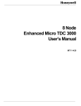
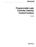
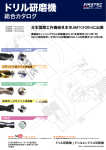
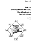
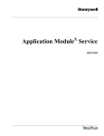
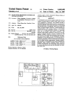
L
8 Node
Multinode Module Service
MT13-420
L
Implementation
8 Node Micro TDC 3000
8 Node
Multinode Module Service
MT13-420
Release 430
CE Compliant
7/95
Copyright, Trademarks, and Notices
Printed in U.S.A. — © Copyright 1995 by Honeywell Inc.
Revision 02 - July 31, 1995
While this information is presented in good faith and believed to be accurate,
Honeywell disclaims the implied warranties of merchantability and fitness for a
particular purpose and makes no express warranties except as may be stated in its
written agreement with and for its customer.
In no event is Honeywell liable to anyone for any indirect, special or consequential
damages. The information and specifications in this document are subject to
change without notice.
About This Publication
This publication provides instructions for use by the system service personnel, to service the
Multinode Module. It will help you determine how to perform service required on the module and to
identify spare parts. It also provides disassembly/assembly instructions useful when replacing the
required part.
This publication is to be used in conjunction with the remainder of the TDC 3000X bookset.
This publication supports TDC 3000X software release 430 and CE Compliant hardware.
Any equipment designated as “CE Compliant” complies with the European Union EMC and
Health and Safety Directives. All equipment shipping into European Union countries after
January 1, 1996 requires this type of compliance—denoted by the “CE Mark.”
Change bars are used to indicate paragraphs, tables, or illustrations containing changes that have
been made to this manual effective with Release 430 and CE Compliancy. Pages revised only to
correct minor typographical errors contain no change bars.
Standard Symbols
The following defines standard symbols used in this publication
Scope
ATTENTION
Notes inform the reader about information that is required, but not
immediately evident
CAUTION
Cautions tell the user that damage may occur to equipment if proper care is
not exercised
WARNING
Warnings tell the reader that potential personal harm or serious economic
loss may happen if instructions are not followed
OR
53893
53894
Ground connection to building safety ground
Ground stake for building safety ground
DANGER
SHOCK HAZARD
53895
Electrical Shock Hazard—can be lethal
DANGER
HIGH VOLTAGE
53896
Electrical Shock Hazard—can be lethal
53897
Rotating Fan—can cause personal injury
Table of Contents
1
INTRODUCTION
1.1
1.2
2
MODULE DESCRIPTION
2.1
2.2
2.2.1
2.2.2
2.2.3
2.2.4
2.3
2.4
2.5
3
Overview
Related Publications
General Description
Module and Node Configurations
Multinode Module Node Configurations
Multinode Module Node Configurations (CE Compliant)
Multinode Module Board Types
Replacement Board Application Notes
Front Panel
Rear Panel
Field Adjustment
TEST/TROUBLESHOOTING
3.1
Tests
3.2
Test Procedures
3.3
Troubleshooting
3.3.1
Power Supply/Fan
3.3.2
PWB Troubleshooting
3.3.2.1
Controller Boards
3.3.2.2
Processor Board K2LCN
3.3.2.3
EPDG Board
4
DISASSEMBLY/ASSEMBLY
4.1
4.2
5
SPARE PARTS
5.1
6
Disassembly
Assembly
Introduction
STARTUP
6.1
6.2
Visual Checks
Initialize Module
APPENDIX A—ALPHANUMERIC DISPLAYS
A.1
Recommended Actions for Specific Code Occurrences
INDEX
Multinode Module Service
i
7/95
Multinode Module Service
ii
7/95
1
INTRODUCTION
Section 1
1.1 OVERVIEW
This manual provides detailed instructions for maintenance, test, troubleshooting, and
repair of the Multinode Module shown in Figure 1-1 (with front cover installed) and Figure
1-2. The Multinode Module will not have the front cover installed when mounting in
Micro TDC 3000 or LCN cabinets. The troubleshooting, disassembly, and assembly
procedures are effective down to the optimum replaceable-unit (ORU) level. An ORU parts
list is included and is keyed to a module-exploded view that is also used with the
disassembly and assembly procedures.
53679
Figure 1-1 — Multinode Module
Multinode Module Service
1-1
7/95
1.1
This manual also contains information about the EC compatible Ten-Slot Module. It
accommodates both the older and newer EC I/O board designs. The EC card file remains
the same in all other details except each I/O board has a faceplate which provides grounding
of the board and cable shield to the card file. The fan intake and exhaust openings on the
sides of the module are covered with a honeycomb wire mesh for EC Compliant protection.
The EC I/O card file is shown in Figure 1-2.
SPC-3 I/O
EPDGC I/O
TP-485-3 I/O
53898
Figure 1-2 — Multinode Module for EC
1.2 RELATED PUBLICATIONS
The following related publications should be referred to as required and available:
Title
Binder
Maintenance Test Operations
System Maintenance Guide
Test System Executive
Hardware Verification Test System
Core Module Test System
LCN Service/Local Control Network - 1
LCN Service/Local Control Network - 1
LCN Service/Local Control Network - 3
LCN Service/Local Control Network - 3
LCN Service/Local Control Network - 3
8 Node Micro TDC 3000 User's Manual
Implementation/8 Node Micro TDC 3000
Multinode Module Service
1-2
7/95
2
MODULE DESCRIPTION
Section 2
2.1 GENERAL DESCRIPTION
The Multinode Module is designed to mount either horizontally in a standard NEMA rack
or vertically in a cabinet (or tower) designed to stand vertically on the floor. Cooling is
provided by four fans in one side of the module enclosure. An integral power supply is
located at the bottom (or side) of the module.
Each Multinode Module supports up to four functional nodes in the TDC 3000 System.
Each node occupies a specific address on the Local Control Network (LCN). Figure 2-1
illustrates a typical Micro TDC 3000 System using two Multinode Modules in vertical
cabinets.
(Example)
DEC VAX
LEFT TOWER
Optional Universal
Station
Optional
Programmable
Logic Controller
Gateway
RIGHT TOWER
History Module
Application
Module
Universal
Station
LCN
620 LCS
(Example)
Optional Redundant
Network Interface
Module
UNIVERSAL
CONTROL NETWORK
Optional
Computer
Gateway
Network Interface
Module
Advanced Process
Manager
Advanced Process
Manager
Process Manager
Logic Manager
53296
Figure 2-1 — Typical Micro TDC 3000 Multinode Module Application
Multinode Module Service
2-1
7/95
2.2
2.2 MODULE AND NODE CONFIGURATIONS
Circuit board slots are numbered from 1 to 10 starting at the bottom (nearest the power
supply). When the module is oriented vertically, the slots are numbered from right to left.
Nodes within a single Multinode Module are in a 3/3/2/2 arrangement, with slots 1 through
3 containing the first node, 4 through 6 containing the second node, slots 7 and 8
containing the third node, and slots 9 and 10 containing the fourth node.
The functional control boards are installed in the front card file of the module so that status
indicators on the boards may be viewed through the transparent cover. If an Input/Output
(I/O) adapter board (or paddleboard) is directly associated with a functional control board,
it is installed in the slot behind it in a card file at the rear of the module. Paddleboards
which do not perform an I/O function may also be installed in the rear card file in an unused
slot.
Multinode Module Service
2-2
7/95
2.2.1
2.2.1 Multinode Module Node Configurations
Because of the limited board space, the boards used to construct various nodes must
contain only certain boards and be configured as shown in Table 2-1.
CAUTION
Power must be removed from the module whenever you are removing or installing any board,
including an I/O paddleboard. Be sure that an I/O paddleboard is installed in the correct slot;
some boards have only one slot that they can be installed in without causing damage. I/O
paddleboards plugged into the wrong slot can cause traces on the backplane to burn open.
In the following table, slot numbers are identified by a-b-c. Remember, in the Multinode
Module 3/3/2/2 arrangement, slots are grouped by node, therefore, a given node may
occupy slots 1-2-3, 4-5-6, 7-8, or 9-10 to match slots a-b-c, or only a-b.
Table 2-1 — Node Configurations for Multinode Modules
Application Module (AM)
Slot
Front
Universal Station (US)
Rear
Slot
b
a
K2LCN-4/6/8 (4)
c
EPDG
b
Empty (3)
a
K2LCN-3/4 (5)
Network Interface Module (NIM)
Slot
Front
Front
EPDG(P) I/O
(1, 2)
History Module (HM)
Rear
Slot
Front
b
EPNI
NIM MODEM
b
SPC
a
K2LCN-2
(1, 2)
a
K2LCN-2
Notes:
Rear
Rear
SPC I/O
(1) A TP485 I/O card is located in Slot 1 and 9 of the modules in the Micro TDC 3000.
(2) The TP485 in Slot 9 provides the interface to the twisted pair, short distance
(≤10 meters) TPLCN.
(3) The EPDG board set should be slots 3 and 6 with slots 2 and 5 empty.
(4) Standard AM is 4 Mw; optional is 6 Mw and 8 Mw. EC Compliant has 4 Mw and 8 Mw
only.
(5) Standard US is 4 Mw; optional is 3 Mw. EC Compliant has 4 Mw and 6 Mw only.
(Continued)
Multinode Module Service
2-3
7/95
2.2.1
CAUTION
Power must be removed from the module whenever you are removing or installing any board,
including an I/O paddleboard. Be sure that an I/O paddleboard is installed in the correct slot;
some boards have only one slot that they can be installed in without causing damage. I/O
paddleboards plugged into the wrong slot can cause traces on the backplane to burn open.
Note that a given node may occupy slots 1-2-3, 4-5-6, 7-8, or 9-10 to match slots a-b-c, or
only a-b.
Table 2-1 — Node Configurations for Multinode Modules (Continued)
Computer Gateway (CG)
Slot
Front
PLC Gateway (PLCG)
Rear
Slot
c
CLI
a
K2LCN-4
CLI I/O
b
PLCI
a
K2LCN-2
Redundant NIM
Front
PLCI I/O
Network Gateway (NG)
Rear
Slot
Front
Rear
NGIO
b
EPNI
NIM MODEM
b
NGI
a
K2LCN-3
(1, 2)
a
K2LCN-2
Notes:
Rear
c
b
Slot
Front
(1) A TP485 I/O card is located in Slot 1 and 9 of the modules in the Micro TDC 3000.
(2) The TP485 in Slot 9 provides the interface to the twisted pair, short distance
(≤10 meters) TPLCN.
Multinode Module Service
2-4
7/95
2.2.2
2.2.2 Multinode Module Node Configurations (CE Compliant)
Because of the limited board space, the boards used to construct various nodes must
contain only certain boards and be configured as shown in Table 2-1.
CAUTION
Power must be removed from the module whenever you are removing or installing any board,
including an I/O paddleboard. Be sure that an I/O paddleboard is installed in the correct slot;
some boards have only one slot that they can be installed in without causing damage. I/O
paddleboards plugged into the wrong slot can cause traces on the backplane to burn open.
In the following table, slot numbers are identified by a-b-c. Remember, in the Multinode
Module 3/3/2/2 arrangement, slots are grouped by node, therefore, a given node may
occupy slots 1-2-3, 4-5-6, 7-8, or 9-10 to match slots a-b-c, or only a-b.
Table 2-2 — Node Configurations for Multinode Modules (CE Compliant)
Application Module (AM)
Slot
Front
Universal Station (US)
Rear
Slot
b
a
K2LCN-4/8 (4)
c
EPDG2
b
Empty (3)
a
K2LCN-4/6 (5)
Network Interface Module (NIM)
Slot
Front
Front
EPDGC I/O
(1, 2)
History Module (HM)
Rear
Slot
Front
b
EPNI
NIM MODEM
b
SPC
a
K2LCN-2
(1, 2)
a
K2LCN-2
Notes:
Rear
Rear
SPC3 I/O
(1) A TP485 I/O card is located in Slot 1 and 9 of the modules in the Micro TDC 3000.
(2) The TP485 in Slot 9 provides the interface to the twisted pair, short distance
(≤10 meters) TPLCN.
(3) The EPDG2 board set should be slots 3 and 6 with slots 2 and 5 empty.
(4) Standard AM is 4 Mw; optional is 8 Mw. EC Compliant has 4 Mw and 8 Mw only.
(5) Standard US is 4 Mw; optional is 3 Mw. EC Compliant has 4 Mw and 6 Mw only.
(Continued)
Multinode Module Service
2-5
7/95
2.2.2
CAUTION
Power must be removed from the module whenever you are removing or installing any board,
including an I/O paddleboard. Be sure that an I/O paddleboard is installed in the correct slot;
some boards have only one slot that they can be installed in without causing damage. I/O
paddleboards plugged into the wrong slot can cause traces on the backplane to burn open.
Note that a given node may occupy slots 1-2-3, 4-5-6, 7-8, or 9-10 to match slots a-b-c, or
only a-b.
Table 2-2 — Node Configurations for Multinode Modules (CE Compliant) (Continued)
Computer Gateway (CG)
Slot
Front
PLC Gateway (PLCG)
Rear
Slot
c
CLI
a
K2LCN-2
CLI I/O
b
PLCI
a
K2LCN-2
Redundant NIM
Front
PLCI I/O
Network Gateway (NG)
Rear
Slot
Front
b
EPNI
NIM MODEM
b
NGI
a
K2LCN-4
(1, 2)
a
K2LCN-4
Notes:
Rear
c
b
Slot
Front
Rear
NGFOM
(1) A TP485 I/O card is located in Slot 1 and 9 of the modules in the Micro TDC 3000.
(2) The TP485 in Slot 9 provides the interface to the twisted pair, short distance
(≤10 meters) TPLCN. The TP485 in Slot 1 provides the interface to the module
temperature sensors.
Multinode Module Service
2-6
7/95
2.2.3
2.2.3 Multinode Module Board Types
The board types listed in Table 2-3 are the current production board types suitable for use
in the Multinode Module.
Table 2-3 — Multinode Module Board Types
Board
Type
Description
CLI
Communications Line Interface Board
(PN 80360206-001)
CNI I/O
Communications Network Interface
(PN 51304537-100)
CNI I/O
Communications Network Interface I/O Brd (EC)
(PN 51304537-200)
EPDG
Enhanced Peripheral Display Generator
(PN 51401286-100)
EPDG2
Enhanced Peripheral Display Generator (EC)
(PN 51402089-100)
K2LCN-2
High Performance/Density Processor Board
(PN 51401551-200)
K2LCN-3
High Performance/Density Processor Board
(PN 51401551-300)
K2LCN-4
High Performance/Density Processor Board
(PN 51401551-400)
K2LCN-6
High Performance/Density Processor Board
(PN 51401551-600)
TP485
TPLCN/Temperature-Sensor Interface Card
(PN 51304776-100)
TP485-3
Temp.-Sensor I/O Face Plate w/connector (EC)
(PN 51304776-300)
TP485-4
Temp.-Sensor I/O Face Plate w/o connector (EC)
(PN 51304776-400)
NIM MODEM
Network Interface Module MODEM Card
(PN 51304511-100)
PLCI
Programmable Logic Controller Interface Board
(PN 51400997-100)
EPLCI
Enhanced Prog. Logic Controller Interface I/O
(PN 51304812-100)
EPNI
Enhanced Process Network Interface Board
(PN 51401583-100)
SPC
Smart Peripheral Controller Board
(PN 51401052-100)
NGI
Network Gateway Interface Board
(PN 51401583-200)
EPDGP I/O
Enhanced Peripheral Display Generator Interface Card (PN 51401286-100)
EPDGC I/O
Enhanced Peripheral Dis. Gen. Int. Card (EC)
(PN 51402477-100)
SPC I/O
Smart Peripheral Controller Interface Card
(PN 51304156-100)
SPC3
Smart Peripheral Controller Interface Card (EC)
(PN 51305088-100)
Multinode Module Service
2-7
7/95
2.2.3
Table 2-3 — Multinode Module Board Types (Continued)
Board
Type
Description
CLI I/O
Communications Line Interface I/O Card (RS-232C)
(PN 80360209-001)
CLI/B
Comm. Line Interface I/O Card (RS-232C) (EC)
(PN 51305090-100)
CLI I/O
Communications Line Interface I/O Card (RS-449)
(PN 80360230-001)
CLI/A
Comm. Line Interface I/O Card (RS-449) (EC)
(PN 51305091-100)
PLCI I/O
Programmable Logic Controller Interface I/O Card
(PN 51195096-100)
PLCI I/O
Prog. Logic Controllers Interface I/O Card (EC)
(PN 51195096-200)
NGIO
Network Gateway Interface I/O Card
(PN 51304472-100)
CLCN I/O
Local Control Network I/O Card (EC)
(PN 51305072-100)
Refer to subsection 2.2.3 Replacement Board Application Notes, for information about
compatible replacements.
2.2.4 Replacement Board Application Notes
Table 2-4 lists boards which are dependent upon a minimum software release.
Table 2-4 — Replacement Board Applications
BOARD
TYPE
MINIMUM
DESCRIPTION
SOFTWARE
RELEASE *
K2LCN
68020 processor and memory board used in all nodes
320
EPDG
With the EPDGP I/O board, operates the 20" noninterlaced CRT
monitor. The EPDGP I/O also has a Cartridge Disk Interface.
320
TP485
Paddleboard that interfaces short-distance LCN used in the
Micro TDC 3000, and interfaces the cabinet temperature sensors
(sensors on non-CE Compliant equipment only).
320
TP485-3
I/O
I/O board interfaces the current loop interface between the
modules located in a Micro TDC 3000 tower.
XXX
TP485-4
I/O
I/O board interfaces the current loop interface between the
modules located in a Micro TDC 3000 tower.
XXX
*All boards are upwards compatible.
Multinode Module Service
2-8
7/95
2.3
2.3 FRONT PANEL
Controls on the front panel of the power supply consist of a POWER switch, a RESET
button, a FAN CONTROL, and a LO-NOM-HI margin jumper. The function and operation of
the power and reset controls are discussed elsewhere in this manual. The margin jumper is
a power supply test/maintenance diagnostic aide and should be left in the NOM (center)
jumper position at all times. The EC power supply contains a fan control switch/jumper
and is set for either a thermally-controlled or fixed-fan power (see Figure 3-2). One setting
varies the fan voltage with temperature and load. The other setting provides a continuous
27 volts.
The front panel contains indicators that provide status of the unit’s performance and aid in
fault isolation. The LED indicators on the bottom left of the front panel (the power supply)
give an indication of the power-supply status. Another indicator on the fan assembly
lights if the fan assembly fails. LEDs on each of the boards are used in conjunction with an
alphanumeric display on the processor board to isolate malfunctions on the boards. Further
information on the use of the module indicators is located in Section 3 of this manual.
2.4 REAR PANEL
The rear panel contains the I/O boards (paddleboards), chassis power-cable, a 100-pin
backplane breakout board (if provided), and a grounding lug. As shown in Table 2-1 the
I/O boards are installed in the chassis in the slot corresponding in number to the applicable
board installed in the front of the module. All communication with the Micro TDC 3000 is
through the I/O boards.
There are two methods of communicating between nodes on the system. The conventional
LCNI I/O paddleboards form the Local Control Network with coaxial cables that run to all
of the LCN nodes in a network. In the network, all LCN I/O boards are connected by T
connectors and cable (or to a terminating load on the last T in a series). Because of loading
characteristics, the minimum LCN cable length is 2 meters (6 feet), so there may appear to
be some cable “waste” when nearby LCN boards are interconnected. In all LCN cabling,
the I/O board connectors are marked A and B; make sure that the A cable connects to the A
connector and that the B cable is connected to the B connector.
A special short distance LCN network has been designed which uses twisted pair and
multinode module backplane wiring instead of coaxial cable and T connectors. The I/O
paddleboards used for this network are the TP485 boards. This twisted pair LCN cabling
follows the RS 485 interface standard. One of the K2LCN processor boards and TP485
I/O cards in slot 9 of each tower supplies clock to other nodes on the short distance
network. The twisted pair cables which tie this short distance LCN together are keyed so
that cables A and B cannot be misconnected and terminating loads are built-in.
Ribbon cables are used to connect to such items as the Winchester Drive, Cartridge Drive,
and other peripherals. Other connectors, for example RS 232C or RS 449 on the
Computer Gateway, are also used.
Multinode Module Service
2-9
7/95
2.5
2.5 FIELD ADJUSTMENT
There are no field adjustments for the Multinode Module. Each K2LCN board, however,
has a node address jumper-pack that must be characterized for the particular node address it
occupies on the TPLCN. Refer to subsection 8.1 of the LCN System Installation manual
for system pinning.
A replacement power supply must be pinned for internal (INT) clock only (see Figure 2-2).
(INT)
With Link Clock
(EXT)
No Link Clock
E20
E23
E21
52389
Figure 2-2 — Power Supply Showing Location of Clock Jumper
Multinode Module Service
2-10
7/95
3
TEST/TROUBLESHOOTING
Section 3
3.1 TESTS
Testing of the Multinode Module is accomplished through both hardware/firmware tests
and software. Hardware/firmware tests are built into the module to provide two means of
functionally checking the unit, whether or not it is connected to the LCN. The first test is
initiated when power is applied. Pressing the RESET button also initiates the hardware/
firmware test. Software tests can be accomplished when the module is connected to the
system. As an example, loading each node's personality initiates a software Quality Logic
Test (QLT).
There may be up to four nodes physically contained in a Multinode Module. Each node has
a processor which can be loaded and tested independently and each node has a different
LCN address. The RESET button simultaneously initiates self-tests on all nodes in the
module.
Figure 3-1 is a flow diagram showing the relationship of the hardware and software tests.
3.2 TEST PROCEDURES
NOTE
Each Node in a Multinode Module must have a processor board installed before it can be
tested. Multiple functions, such as processor, LCN interface, and memory, are physically
located on the K2LCN board.
Initiate power-up tests by setting the power switch to on. The red LEDs on the boards in eacsh
node light for a few seconds (less than 30), then turn off and the green LEDs turn on as each of
the boards passes its processor dialog tests. When the tests have been completed, each
node's alphanumeric display indicates its node address.
Check the power supply ERROR and POWER OK LEDs at the bottom of the unit and the FAN
ALARM LED on the right side of the unit to ensure that no red LEDs are on and the green
POWER OK LED is lighted.
Press the RESET button. The red LEDs momentarily go on as above, then go out when the
green LEDs come on. Recheck the power supply, board, and fan LEDs as above. Note
that each alphanumeric display indicates its node address.
If any of the above conditions cannot be met, refer to subsection 3.3 Troubleshooting.
Multinode Module Service
3-1
7/95
3.2
POWER ON/RESET
INITIATES
HDW/FMW TESTS
PASS
TEST
LIGHT RED LED;
LOAD ALPHNUM
DISPLAY WITH
ERROR CODE
NO
YES
LIGHT GRN LED;
RECORD STATUS
IN MCT
OPERATOR CHK
LEDS/ALPHNUM
DISPLAY
LOAD ALPHNUM
DISPLAY WITH
NODE NUMBER
NODE GOES TO
FAILED STATE;
XMIT NOTICE
OF CRITICAL
MALFUNCTIONS
XMIT "ALIVE" MSG
TO OPERATOR
CONSOLE
LOAD AND RUN
QLT
*
LIGHT RED LED;
LOAD ALPHNUM
DISPLAY WITH
ERROR CODE
YES
FATAL
ERROR
RECORD STATUS
IN MCT
NO
LIGHT GRN LED;
LOAD ALPHNUM
DISPLAY WITH
NODE NUMBER
Glossary:
MCT — Module Configuration Table
ALPHNUM — Alphanumeric
HDW/FMW — Hardware/Firmware
QLT — Quality Logic Test
MSG — Message
XMIT — Transmit
CHK — Check
GRN — Green
RECORD
STATUS IN MCT
XMIT "QUALIFIED"
MSG ON LCN
LOAD NODE
PERSONALITY
*
Operator Load Request required
(Except for HM)
CHECK MCT FOR NONFATAL QLT ERRORS
ERRORS
PRESENT
YES
ISSUE MAINTENANCE
RECOMMENDATIONS
NO
CONTINUE
NORMAL
FUNCTIONS
Figure 3-1 — Testing Flow Diagram
Multinode Module Service
2898
3-2
7/95
3.3
3.3 TROUBLESHOOTING
The troubleshooting procedures are grouped by affected ORU and are keyed to the LED
indicators and the alphanumeric display. First, a malfunction symptom is listed, then
instructions are given to check or replace parts in order of the most likely causes. In the
following procedures the indicated LEDs are red unless otherwise stated. Refer to Section
4 for disassembly and assembly instructions. Always turn power off before removing or
replacing a part on the module, as this protects equipment from voltage transients and
ensures proper initialization. If the fault cannot be corrected by performing these
procedures, refer to Appendix A for further information on the alphanumeric display. If
the fault still cannot be isolated, contact the Honeywell Technical Assistance Center (TAC).
CAUTION
All assemblies used in this module are likely to contain electrostatically sensitive devices.
Use personnel grounding strap and grounded work surfaces/equipment. Store and transport parts only in electrostatically safe containers.
3.3.1 Power Supply/Fan
Refer to Figure 3-2. No LEDs light at all.
• Check power cord and power off-on switch.
• Replace power supply.
Red ERROR power-status LED on or green POWER OK LED off.
• Replace power supply.
• If red LED is still on, check for shorted backpanel bus.
FAN ALARM LED on.
WARNING
Rotating parts. Keep fingers and other objects clear of fans.
• If necessary, loosen mounting hardware and slide module out of rack. Check fans. If
all fans are stopped, check the wiring to them.
• If one or more fans are stopped, replace fan assembly.
• Replace power supply.
• Check for missing or defective thermal sensors.
Multinode Module Service
3-3
7/95
3.3.1
10
9
8
7
Fan
Assembly
6
5
4
3
2
Fan Alarm
LED
1
Error
Reset Switch
Power OK
Fan
Control
ON
Lo-Nom-Hi
Jumper Power Supply
54004
Figure 3-2 — EC Power Supply and Fan Indicators
Multinode Module Service
3-4
7/95
3.3.2
3.3.2 PWB Troubleshooting
The K2LCN processor boards used in the Multinode Module have indicators on the front
of the board to indicate error conditions. These processor boards have a red LED bar
display with no labels as shown in Figure 3-3.
In the sections to follow, use these indicators in conjunction with indicators on the inputoutput and controller boards to find the faulty PWB.
Data
DTAK BGAK Data
RST/PWR Self-Test Compare Time Time Parity
Fail
Error
Error
Out
Out
Error
Self-Test
Pass
(Green)
Bus
Error
EDAC
Multi-Bit
Error
EDAC
Single-Bit
Error
LCN
Transaction
Error
Node
Address/Error
Display
TX
(Yellow)
Red LEDs
40022
Figure 3-3 — K2LCN Indicators
NOTE
Remove module front panel to view the board LEDs and to check the alphanumeric display
(the Node Address/Error Display).
The Node Address/Error Display provides an alphanumeric code to aid in finding ORU
faults. When directed to this display, consult Appendix A to interpret its meaning.
Multinode Module Service
3-5
7/95
3.3.2
3.3.2.1 Controller Boards (CLI EPNI NGI SPC)
SELF TST/ERR light does not go out.
• Replace controller board.
• Ensure that I/O paddleboard is properly installed.
• Replace I/O paddleboard.
SELF TST/ERR light goes out, but PASS MOD TEST (green) light does not light on
controller board.
• Replace controller board.
• Ensure that I/O paddleboard is properly installed.
• Replace I/O paddleboard.
• Replace K2LCN.
SELF TST/ERR light goes out, but PASS MOD TEST (green) light does not light on
all controllers.
• Replace K2LCN.
• Remove controller board, then apply power. Repeat for each controller board until
fault is cleared. Retry extracted boards.
BUS TRAN ERR light is lighted on controller, and DTAK TIME OUT is lighted on
the K2LCN.
• Replace controller board.
• Replace K2LCN.
BUS TRAN ERR light is lighted on a controller, and BGAK TIME OUT is lighted on the
K2LCN.
• Remove controller board, then apply power. If fault is cleared, replace controller
board.
• Replace K2LCN.
Multinode Module Service
3-6
7/95
3.3.2
3.3.2.2 Processor Board K2LCN
DATA PAR ERR and BUS ERR are lit.
• Check alphanumeric display. First two digits denote the slot number (in the node) of
the failed board. (Third digit/letter is the failed test number.)
• Replace indicated board.
• Replace processor board.
3.3.2.3 EPDG Board
SELF TST/ERR light does not go out on EPDG.
• Replace EPDG.
• Replace processor board.
SELF TST/ERR light goes out on EPDG, but PASS MOD TEST (green) light
does not light on EPDG.
• Replace EPDG.
• Replace processor board.
BUS TRAN ERR is lighted on EPDG and DTAK TIME OUT is lighted on K2LCN, but the BUS
ERR light is not on.
• Replace EPDG.
• Replace processor board.
BUS TRAN ERR is lighted on EPDG and DTAK TIME OUT and BUS ERR is lighted on
K2LCN.
• Replace EPDG.
• Replace processor board.
Multinode Module Service
3-7
7/95
Multinode Module Service
3-8
7/95
4
DISASSEMBLY/ASSEMBLY
Section 4
4.1 DISASSEMBLY
The Module should be disassembled only to the extent necessary to service or replace
defective parts. The following procedures require the use of a blade-tip or Phillips (if EC
hardware) screwdriver, personnel grounding strap, and antistatic fixtures and equipment.
Item numbers called out in the procedures refer to ballooned numbers in the exploded
Multinode Module diagram, Figure 4-1, and are keyed to the item numbers in Spare Parts,
Section 5.
1. Remove front panel (if supplied) from chassis (1) by turning two quarter-turn fasteners
on the right side of the panel and swinging panel out.
CAUTION
All assemblies used in this Module are likely to contain electrostatically sensitive devices.
Use a personnel grounding strap and grounded work surfaces and equipment. Store and
transport parts only in electrostatically safe containers.
2. Remove boards (2) by pulling out on retainers and sliding boards out of chassis.
3. Remove fan assembly (5) by unscrewing bail-headed screws 1/4 turn, counter
clockwise, and sliding out of chassis.
4. Remove power supply (4) by pulling retainers and sliding out of chassis.
5. Remove I/O boards (6) from rear chassis. If removing EC I/O boards, a Phillips head
screwdriver is required.
Multinode Module Service
4-1
7/95
2
4
1
3
5
6
4.1
Figure 4-1 — Multinode Module Exploded View
Multinode Module Service
4-2
2888
7/95
4.2
NOTE
Before inserting a replacement board:
1. Make certain that the replacement board is at a revision level equal to or later than the
board being replaced.
2. Make certain that the pinning of the node address on a K2LCN board matches
that on the board being replaced.
4.2 ASSEMBLY
1. Assemble I/O boards (6) to rear chassis, taking care not to damage connectors, and
secure board retainers. Care should be taken to ensure that the I/O boards match the
primary boards. If present, reconnect cables to replaced boards.
2. Insert power supply (4) into chassis and secure retainers.
3. Insert fan assembly (5) into chassis and secure bail-headed screws.
4. Insert boards (2) into chassis and secure retainers. If present, reconnect ribbon cables
to replaced boards.
5. Assemble front panel (1) to chassis and secure quarter-turn fasteners.
Multinode Module Service
4-3
7/95
Multinode Module Service
4-4
7/95
5
SPARE PARTS
Section 5
5.1 INTRODUCTION
Table 5-1 lists spare parts for the Multinode Module. Those parts at the ORU level are
marked with an asterisk (*). The listing is arranged in item-number order with the items
keyed to the call-out balloons in Figure 4-1. Also listed are those boards suitable for use in
the Multinode Module configurations. In some cases, more than one part is assigned to an
item number (for instance any one of several board assemblies can occupy a slot in the
module). In this situation, the list is in part-number order.
Table 5-1 — Parts List
ITEM
PART
NUMBER
1
51400919-100
10-Slot Module Cover Assembly (may not be required)
2*
51400955-100
PNI Board Assembly, Process Network Interface
2*
51400955-100
EPNI/NGI
2*
51400997-100
PLCI Programmable Logic Controller Interface
2*
51401052-100
SPC Board Assy., Smart Peripheral Interface Controller
2*
51401286-100
EPDG Board Assy., Enhanced Peripheral Display Generator
2*
51401286-100
EPDG2 Board Assy.
2*
51401551-200
K2LCN Board Assembly, Processor (LCN Intf & 2 M Memory)
2*
51401551-300
K2LCN Board Assembly, Processor (LCN Intf & 3 M Memory)
2*
51401551-301
K2LCN Board Assembly
2*
51401551-400
K2LCN Board Assembly, Processor (LCN Intf & 4 M Memory)
2*
51401551-600
K2LCN Board Assembly, Processor (LCN Intf & 6 M Memory)
2*
51401551-601
K2LCN Board Assembly
2*
51401583-100
EPNI Board Assembly, Enhanced Process Network Interface
DESCRIPTION
(Continued)
Multinode Module Service
5-1
7/95
5.1
Table 5-1 — Parts List (Continued)
PART
ITEM
NUMBER
DESCRIPTION
2*
51401583-200
NGI Board Assembly, Network Gateway Interface
2*
80360206-001
CLI Board Assembly, Computer/LCN Interface
3*
51401782-100
3/3/2/2 Split Node Cardfile (w/out power supply, fan assembly)
3*
51402491-100
3/3/2/2 Split Node Cardfile, (EC)
4*
51195066-200
Power Supply
4*
51196654-100
10-Slot Pwr Supply w/Temp Sense Sw. (EC)
5*
51400647-100
10-Slot Fan Assembly (large)
6*
51304511-100
NIM MODEM Adapter Board Assembly
6*
51304511-200
NIM MODEM Adapter Board Assembly (EC)
6*
51304156-100
SPC I/O Adapter Board Assembly
6*
51305088-100
SPC3 I/O Adapter Board Assembly, (EC)
6*
51304584-100
EPDGC I/O Adapter Board Assembly, (EC)
6*
51304584-100
EPDGP I/O Adapter Board Assembly
6*
51304776-100
TP485 Adapter Board Assembly
6*
51304472-100
NGIO Adapter Board Assembly
6*
80360209-001
CLI I/O Adapter Board Assembly (RS-232C)
6*
51305090-100
CLI/B Card (RS-232C) (EC)
6*
80360230-001
CLI I/O Adapter Board Assembly (RS-449)
6*
51305091-100
CLI/A Card (RS-449) (EC)
6*
51304537-100
CNI Communications Network Interface
6*
51304537-200
CNI I/O Communications Network Interface I/O Brd, (EC)
6*
51195096-100
PLCI I/O Adapter Board Assembly
6*
51195096-200
PLCI I/O Adapter Board Assembly (EC)
(Continued)
Multinode Module Service
5-2
7/95
5.1
Table 5-1 — Parts List (Continued)
PART
ITEM
NUMBER
*
51304421-100
PLCG Relay Panel Assembly
*
51304421-200
PLCG Relay Panel Assembly (EC)
51303508-100
Power Cord, 125 V
51303508-200
Power Cord, 250 V
51308115-100
Power Cord (EMI Filter), 120/240 V (EC)
51191840-X0X
Power Cable, Shielded, PVC Jacket, 120/240 V (EC)
Multinode Module Service
DESCRIPTION
5-3
7/95
Multinode Module Service
5-4
7/95
6
STARTUP
Section 6
6.1 VISUAL CHECKS
• Check Module power and signal cables to ensure that they are present and tight.
• Check ground strap and/or leads on rear of chassis for good connection.
• Ensure that all boards and power supply are fully inserted into the connectors and that
board retainers are secured.
6.2 INITIALIZE MODULE
• Set power switch to on. Check all LEDs in accordance with Test Procedures,
subsection 3.2.
• Press RESET button. Check LEDs again as above.
Multinode Module Service
6-1
7/95
Multinode Module Service
6-2
7/95
A
ALPHANUMERIC DISPLAYS
Appendix A
The alphanumeric display enhances the man-machine interface by displaying hardware/
firmware and software-driven messages. In interpreting the messages, special attention
should be paid to the left-most element. As shown in Figure A-1, this element can have
four distinct states and the correct reading of the display is critical to understanding the
message.
First "Window" Interpretation
//
//
(blank) or (1) — normal (physical node address)
(-) or (-1) — Error indication
"Window" value ranges
(0, 1, 2, 3, 4, 5, 6, 7, 8, 9, A, -, C, blank, E, F)
(-, -1, blank)
Figure A-1 — Three-window Display Interpretation
2470
NOTE
The error code interpretations that follow do not apply while the node is executing test
software such as HVTS.
Multinode Module Service
A-1
7/95
A
A.1 Recommended Actions for Specific Code Occurrences
NOTE
The Multinode Module contains a maximum of four nodes with each node occupying slots
which are numbered 1-2-3, 4-5-6, 7-8, or 9-10. Each node’s processor (and its alphanumeric
display) is always located in slot 1 or 4 or 7 or 9.
To simplify the following explanation, slots are identified by a, b, or c which define the
1st, 2nd, or 3rd board in a given node regardless of its physical slot location.
Please note, when multiple recommendations are given for a window code-value, they are
organized in order from most to least likely.
Recommendations marked with * indicate an unimplemented code-value. Any such
occurrence should be brought to the attention of Honeywell TAC.
Window values marked as
-
0
//
-
1
n
n=(-)
//
are "don't care" values.
replace K2LCN*
replace K2LCN; replace boards in slots b through c in turn
n=(1 thru 7) replace K2LCN
n=(other)
-
2
replace K2LCN*
n
n=(1 thru 7) replace board in slot b; replace K2LCN; replace the module backplane or
chassis assembly
n=(-) or (C) replace board in slot b; replace K2LCN; replace board in slot c if one
exists; replace the module backplane or chassis assembly
n=(other)
replace K2LCN*
Multinode Module Service
A-2
7/95
A
-
3
n
n=(1 thru 7),
(-) or (C) replace board in slot b/c; replace K2LCN; replace the module backplane
or chassis assembly
n=(other)
-
4
replace K2LCN*
n
n=(1 thru 7),
(-) or (C)
replace K2LCN; replace the module backplane or chassis assembly
n=(other)
-
5
replace K2LCN*
n
n=(1 thru 7),
(-) or (C)
replace K2LCN; replace the module backplane or chassis assembly
n=(other)
-
6
replace K2LCN*
n
n=(1 thru 7),
(-) or (C)
replace K2LCN; replace the module backplane or chassis assembly
n=(other)
-
7
replace K2LCN*
n
n=(1 thru 7),
(-) or (C)
replace K2LCN; replace the module backplane or chassis assembly
n=(other)
replace K2LCN*
Multinode Module Service
A-3
7/95
A
-
8
n
n=(1 thru 7),
(-) or (C)
replace K2LCN; replace the module backplane or chassis assembly
n=(other)
-
9
replace K2LCN*
n
n=(1 thru 7),
(-) or (C)
replace K2LCN; replace the module backplane or chassis assembly
n=(other)
-
A
replace K2LCN*
n
n=(A) or (C) replace K2LCN
n=(other)
replace K2LCN*
-
-
//
replace K2LCN*
-
C
//
replace K2LCN*
-
n
n=(A)
if value persists beyond 30 seconds, replace K2LCN
n=(other)
replace K2LCN*
Multinode Module Service
A-4
7/95
A
-
E
n
n=(0)
an unexpected interrupt has occurred, replace K2LCN
n=(1)
replace K2LCN; replace boards in slots b through c in turn;
n=(2)
no working DRAM, replace K2LCN
n=(3)
suspected program error, replace K2LCN
n=(5)
unverified cause of Level 7 interrupt, - replace K2LCN; replace the
power supply
n=(other)
replace K2LCN*
-
F
//
replace K2LCN*
-1
0
//
n=(1 thru 7),
(-) or (C) replace K2LCN board; replace the module backplane or chassis
assembly
n=(other)
-1
1
replace K2LCN*
//
replace K2LCN*
-1
2
//
replace K2LCN*
-1
3
//
replace K2LCN*
-1
4
//
replace K2LCN*
Multinode Module Service
A-5
7/95
A
-1
5
//
replace K2LCN*
-1
6
//
replace K2LCN*
-1
7
n
n=(0), (1)
check for duplicate node number; check/replace TPLCN cable; replace
K2LCN
n=(2 thru 5) replace K2LCN board; replace K2LCN in other nodes
n=(6)
replace Winchester (drive or interface)
n=(7 thru 9) reload node, replace K2LCN
n=(other)
-1
8
replace K2LCN*
n
n=(0 thru 2) replace EPDG board
n=(3)
reload node, replace K2LCN
n=(4,5,8)
check for proper release version of the software; reboot system
n=(9)
check/replace TPLCN cable; check for proper release version of the
software; reboot system
n=(A,C,E,F) suspect the load image; check the software release version and reload the
node
n=(other)
replace K2LCN*
Multinode Module Service
A-6
7/95
A
-1
9
n
n=(0,3,4,5) reboot system
n=(1 or 2)
record error messages and call Honeywell TAC
n=(6)
use SMCC to find defective board
n=(7,8)
check memory capacity; replace K2LCN; check and reload software
n=(9)
check and reload software; replace K2LCN
n=(other)
replace K2LCN*
-1
A
//
replace K2LCN*
-1
-
//
replace K2LCN*
-1
C
//
replace K2LCN*
-1
//
replace K2LCN*
-1
E
n
n=(2)
replace board in slot number a
n=(3)
replace board in slot number c
n=(other)
replace K2LCN*
Multinode Module Service
A-7
7/95
A
-1
F
n
n=(0 thru 8),
(E) or (F) replace K2LCN
n=(9) or (A) replace K2LCN*
n=(-) or (C),
or (blank)
replace K2LCN board; if error repeats, look for bus problems
n=(other)
check and/or replace backplane or chassis assembly
Multinode Module Service
A-8
7/95
Index
Topic
Section Heading
Alphanumeric Displays
APPENDIX A
Assembly
Disassembly
DISASSEMBLY/ASSEMBLY
EC Compliant
Field Adjustment
Front Panel
General Description
Initialize Module
INTRODUCTION
MODULE DESCRIPTION
Module and Node Configurations
Multinode Module (EC Compliant
Multinode Module Node Configurations
Multinode Module Node Configurations (CE Compliant)
Multinode Module Board Types
Replacement Board Application Notes
Overview
Rear Panel
Related Publications
SPARE PARTS
Introduction
STARTUP
Test Procedures
TEST/TROUBLESHOOTING
Tests
Troubleshooting
Power Supply/Fan
PWB Troubleshooting
Memory Boards
Processor Boards
EPDG Board
Visual Checks
A.1
A
4.2
4.1
4
1.1
2.5
2.3
2.1
6.2
1
2
2.2
1.1
2.2.1
2.2.2
2.2.3
2.2.4
1.1
2.4
1.2
5
5.1
6
3.2
3
3.1
3.3
3.3.1
3.3.2
3.3.2.2
3.3.2.3
3.3.2.4
6.1
Multinode Module Service
Index - 1
7/95
Multinode Module Service
Index -2
7/95
READER COMMENTS
Honeywell IAC Automation College welcomes your comments and suggestions to improve future
editions of this and other publications.
You can communicate your thoughts to us by fax, mail, or toll-free telephone call. We would like to
acknowledge your comments; please include your complet name and address
BY FAX:
Use this form; and fax to us at (602) 313-4108
BY TELEPHONE: In the U.S.A. use our toll-free number 1*800-822-7673 (available in the 48
contiguous states except Arizona; in Arizona dial 1-602-313-5558).
BY MAIL: Use this form; detach, fold, tape closed, and mail to us.
Title of Publication:
C8 Node Multinode Module Service
Issue Date:
7/95
Publication Number:
MT13-420 (R430/EC)
Writer:
D. Downey
COMMENTS: ___________________________________________________________
_______________________________________________________________________
_______________________________________________________________________
_______________________________________________________________________
_______________________________________________________________________
_______________________________________________________________________
_______________________________________________________________________
_______________________________________________________________________
RECOMMENDATIONS:___________________________________________________
_______________________________________________________________________
_______________________________________________________________________
_______________________________________________________________________
_______________________________________________________________________
_______________________________________________________________________
_______________________________________________________________________
_______________________________________________________________________
NAME _______________________________________ DATE ____________________
TITLE _________________________________________________________________
COMPANY _____________________________________________________________
ADDRESS ______________________________________________________________
CITY ________________________ STATE ___________ ZIP ____________________
TELEPHONE _____________________ FAX _________________________________
(If returning by mail, please tape closed; Postal regulations prohibit use of staples.)
Communications concerning technical publications should be directed to:
Automation College
Industrial Automation and Control
Honeywell Inc.
2820 West Kelton Lane
Phoenix, Arizona 85023-3028
FOLD
FOLD
From:
NO POSTAGE
NECESSARY
IF MAILED
IN THE USA
FIRST CLASS
PERMIT NO. 4332
Cut Along Line
BUSINESS REPLY MAIL
PHOENIX, ARIZONA
POSTAGE WILL BE PAID BY ....
Honeywell
Industrial Automation and Control
2820 West Kelton Lane
Phoenix, Arizona 85023-3028
Attention: Manager, Quality
FOLD
Additional Comments:
FOLD
Industrial Automation and Control
Honeywell Inc.
16404 North Black Canyon Highway
Phoenix, Arizona 85023-3099
L
Helping You Control Your World