1
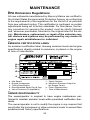
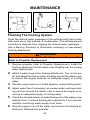
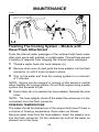
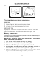
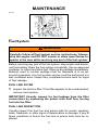
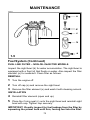
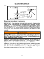
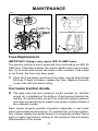
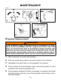
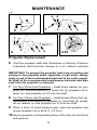
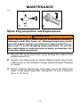
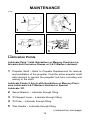
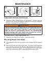
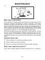
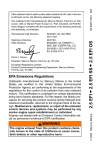
oha4
MAINTENANCE
Outboard Care
To keep your outboard in the best operating condition, it is important
that your outboard receive the periodic inspections and maintenance listed in the Inspection and Maintenance Schedule. We urge
you to keep it maintained properly to ensure the safety of you and
your passengers and retain its dependability.
WARNING
Neglected inspection and maintenance service of your outboard or attempting to perform maintenance or repair on your
outboard if you are not familiar with the correct service and
safety procedures could cause personal injury, death, or
product failure.
Record maintenance performed in Maintenance Log at the back of
this book. Save all maintenance work orders and receipts.
Selecting Replacement Parts For Your Outboard
We recommend using original Mercury Precision or Quicksilver replacement parts and Genuine Lubricants.
WARNING
Using a replacement part that is inferior to the original part
could result in personal injury, death, or product failure.
64
MAINTENANCE
oti1
EPA Emissions Regulations
All new outboards manufactured by Mercury Marine are certified to
the United States Environmental Protection Agency as conforming
to the requirements of the regulations for the control of air pollution
from new outboard motors. This certification is contingent on certain
adjustments being set to factory standards. For this reason, the factory procedure for servicing the product must be strictly followed
and, wherever practicable, returned to the original intent of the design. Maintenance, replacement, or repair of the emission control devices and systems may be performed by any marine SI
engine repair establishment or individual.
oti8
EMISSION CERTIFICATION LABEL
An emission certification label, showing emission levels and engine
specifications directly related to emissions, is placed on the engine
at time of manufacture.
f
g
h
i
a
b
c
d
e
a - Idle Speed
b - Engine Horsepower
c - Timing Specification
d - Recommended Spark Plug & Gap
e - Valve Clearance (if Applicable)
f - Family Number
g - Maximum Emission Output for
the Engine Family
h - Piston Displacement
i - Date of Manufacture
oti7
OWNER RESPONSIBILITY
The owner/operator is required to have engine maintenance performed to maintain emission levels within prescribed certification standards.
The owner/operator is not to modify the engine in any manner that
would alter the horsepower or allow emissions levels to exceed their
predetermined factory specifications.
65
ohd9
MAINTENANCE
Inspection And Maintenance Schedule
BEFORE EACH USE
1. Check that lanyard stop switch stops the engine.
2. Visually inspect the fuel system for deterioration or leaks.
3. Check outboard for tightness on transom.
4. Check steering system for binding or loose components.
5. Visually check steering link rod fasteners for proper tightness.
(page 73)
6. Check propeller blades for damage.
AFTER EACH USE
1. Flush out the outboard cooling system if operating in salt or polluted water. (pages 68 and 69)
2. Wash off all salt deposits and flush out the exhaust outlet of the
propeller and gear case with fresh water if operating in salt
water.
EVERY 100 HOURS OF USE OR ONCE YEARLY, WHICHEVER
OCCURS FIRST
1. Lubricate all lubrication points. Lubricate more frequently when
used in salt water. (page 78)
2. Inspect and clean spark plugs. (page 77)
3. Check engine fuel filter for contaminants. (pages 71 and 72)
4. Adjust carburetor(s) (if required).∗
5. Check engine timing setup.∗
6. Check corrosion control anodes. Check more frequently when
used in salt water. (page 74)
(continued on next page)
∗ These items should be serviced by an authorized dealer.
66
MAINTENANCE
Inspection And Maintenance Schedule
(Continued)
EVERY 100 HOURS OF USE OR ONCE YEARLY, WHICHEVER
OCCURS FIRST
7. Drain and replace gear case lubricant. (page 80)
8. Lubricate splines on the drive shaft.∗
9. Check power trim fluid. (page 79)
10. Inspect battery. (page 70)
11. Check control cable adjustments.∗
12. Remove engine deposits with Mercury Precision or Quicksilver
Power Tune Engine Cleaner.
13. Check tightness of bolts, nuts, and other fasteners.
EVERY 300 HOURS OF USE OR THREE YEARS
1. Replace water pump impeller (more often if overheating occurs
or reduced water pressure is noted).∗
BEFORE PERIODS OF STORAGE
1. Refer to Storage procedure. (page 82)
∗ These items should be serviced by an authorized dealer.
67
goh100
1
MAINTENANCE
2
5
ohe18
Flushing The Cooling System
Flush the internal water passages of the outboard with fresh water
after each use in salt, polluted, or muddy water. This will help prevent
a buildup of deposits from clogging the internal water passages.
Use a Mercury Precision or Quicksilver accessory (or equivalent)
flushing attachment.
WARNING
To avoid possible injury when flushing, remove the propeller.
Refer to Propeller Replacement.
1
Remove propeller (refer to Propeller Replacement). Install the
flushing attachment so the rubber cups fit tightly over the cooling
water intake holes.
2
Attach a water hose to the flushing attachment. Turn on the water and adjust the flow so water is leaking around the rubber cups
to ensure the engine receives an adequate supply of cooling
water.
3
4
Start the engine and run it at idle speed in neutral shift position.
5
Check for a steady stream of water flowing out of the water pump
indicator hole. Continue flushing the outboard for 3 to 5 minutes,
carefully monitoring water supply at all times.
6
Stop the engine, turn off the water, and remove the flushing attachment. Reinstall the propeller.
Adjust water flow (if necessary) so excess water continues leaking out from around the rubber cups to ensure the engine is receiving an adequate supply of cooling water.
68
goh227
MAINTENANCE
d
c
b
1-4
a
ohe14
Flushing The Cooling System – Models with
Hose Flush Attachment
Flush the internal water passages of the outboard with fresh water
after each use in salt, polluted, or muddy water. This will help prevent
a buildup of deposits from clogging the internal water passages.
1
2
Thread a water hose into hose adaptor (a).
3
Turn on the water and flush the cooling system for a minimum
of 3 minutes.
Remove dust cover (b) and push the hose adaptor into the flush
connector (c) until it locks (snaps) in place.
NOTE: Engine can be stopped or running at idle speed in neutral
when flushing the cooling system. Do not flush engine using a water
system that exceeds 45 psi.
4
Push button (d) in to release the hose adaptor. Reinstall the dust
cover.
NOTE: The hose adaptor shuts off the water flow whenever it is disconnected from the flush connector.
FREEZING TEMPERATURE
The water should be drained out of the engine flush hose If there is
a chance of freezing temperature. Drain water as follows:
Remove water hose from the hose adaptor. Insert the adaptor only
into the flush connector. Tilt the outboard up until all the water as
drained out of the hose.
69
MAINTENANCE
goh101
1
2
ohf2
Top Cowl Removal And Installation
REMOVAL
1
Unlock the rear latch by pushing lever down.
2
Lift rear of cowl and disengage front hook.
INSTALLATION
Engage the front hook and push cowl back over the cowl seal.
Push cowl down and move the rear latch lever up to lock.
ohn1
Battery Inspection
The battery should be inspected at periodic intervals to ensure proper engine starting capability.
IMPORTANT: Read the safety and maintenance instructions
which accompany your battery.
1. Turn off the engine before servicing the battery.
2. Add water as necessary to keep the battery full.
3. Make sure the battery is secure against movement.
4. Battery cable terminals should be clean, tight, and correctly installed. Positive to positive and negative to negative.
5. Make sure the battery is equipped with a nonconductive shield
to prevent accidental shorting of battery terminals.
70
goh102
MAINTENANCE
1
ohh1
Fuel System
WARNING
Avoid serious injury or death from gasoline fire or explosion.
Carefully follow all fuel system service instructions. Always
stop the engine and DO NOT smoke or allow open flames or
sparks in the area while servicing any part of the fuel system.
Before servicing any part of the fuel system, stop engine and disconnect the battery. Drain the fuel system completely. Use an approved
container to collect and store fuel. Wipe up any spillage immediately.
Material used to contain spillage must be disposed of in an approved receptacle. Any fuel system service must be performed in a
well ventilated area. Inspect any completed service work for signs
of fuel leakage.
FUEL LINE FILTER
1
Inspect the fuel line filter. If the filter appears to be contaminated,
remove and replace.
IMPORTANT: Visually inspect for fuel leakage from the filter
connections by squeezing the primer bulb until firm, forcing
fuel into the filter.
FUEL LINE INSPECTION
Visually inspect the fuel line and primer bulb for cracks, swelling,
leaks, hardness, or other signs of deterioration or damage. If any of
these conditions is found, the fuel line or primer bulb must be replaced.
71
goh218
MAINTENANCE
e
d
c
b
a
1-5
ohh17
Fuel System (Continued)
FUEL LINE FILTER – NON-OIL INJECTED MODELS
Inspect the sight bowl (b) for water accumulation. The sight bowl is
equipped with a float (d) that floats on water. Also inspect the filter
element (e) for sediment. Clean filter as follows.
REMOVAL
1
Turn the engine off.
2
Turn off cap (a) and remove the sight bowl.
3
Remove the filter element (e) and wash it with cleaning solvent.
INSTALLATION
4
Reinstall filter element (open end up).
5
Place the O-ring seal (c) onto the sight bowl and reinstall sight
bowl with cap. Tighten cap securely.
IMPORTANT: Visually inspect for fuel leakage from the filter by
squeezing the primer bulb until firm, forcing fuel into the filter.
72
MAINTENANCE
goh103
a
d
b
c
ohi1
Steering Link Rod Fasteners
IMPORTANT: The steering link rod that connects the steering
cable to the engine must be fastened using special washer
head bolt (“a” – Part Number 10-14000) and self locking nylon
insert locknuts (“b” & “c” – Part Number 11-34863). These locknuts must never be replaced with common nuts (non locking)
as they will work loose and vibrate off freeing the link rod to disengage.
WARNING
Disengagement of a steering link rod can result in the boat
taking a full, sudden, sharp turn. This potentially violent action can cause occupants to be thrown overboard exposing
them to serious injury or death.
Assemble steering link rod to steering cable with two flat washers (d)
and self locking nylon insert locknut (“b” – Part Number 11-34863).
Tighten locknut (b) until it seats, then back nut off 1/4 turn.
Assemble steering link rod to engine with special washer head bolt
(“a” – Part Number 10-14000) and self locking nylon insert locknut
(“c” – Part Number 11-34863). First torque bolt (a) to 20 lb. ft. (27.1
N·m), then torque locknut (c) to 20 lb. ft. (27.1 N·m).
73
goh219
MAINTENANCE
a
b
2
1
omh3
Fuse Replacement
IMPORTANT: Always carry spare SFE 20 AMP fuses.
The electric starting circuit is protected from overload by an SFE 20
AMP fuse. If the fuse is blown, the electric starter motor will not operate. Try to locate and correct the cause of the overload. If the cause
is not found, the fuse may blow again.
1
Open the fuse holder and look at the silver colored band inside
the fuse. If band is broken, replace the fuse. Replace fuse with
a new fuse with the same rating.
ohk3
Corrosion Control Anode
2
The gear case has two corrosion control anodes (a). Another
anode (b) is installed on the bottom of the transom bracket assembly. An anode helps protect the outboard against galvanic
corrosion by sacrificing its metal to be slowly eroded instead of
the outboard metals.
Each anode requires periodic inspection especially in salt water
which will accelerate the erosion. To maintain this corrosion protection, always replace the anode before it is completely eroded. Never
paint or apply a protective coating on the anode as this will reduce
effectiveness of the anode.
74
MAINTENANCE
goh208
N
N
2
1
3
4-5
ohl8
Propeller Replacement
WARNING
If the propeller shaft is rotated while the engine is in gear,
there is the possibility that the engine will crank over and
start. To prevent this type of accidental engine starting and
possible serious injury caused from being struck by a rotating propeller, always shift outboard to neutral position and remove spark plug leads when you are servicing the propeller.
1
Shift outboard to neutral (N) position.
2
Remove spark plug leads to prevent engine from starting.
3
Straighten the bent tabs on the propeller nut retainer.
4
Place a block of wood between gear case and propeller to hold
propeller and remove propeller nut.
5
Pull propeller straight off shaft. If propeller is seized to the shaft
and cannot be removed, have the propeller removed by an authorized dealer.
75
MAINTENANCE
goh83
e
7
6
f
8
f
d
c
b
a
e
d
c
b
a
9-10
ohl35
Propeller Replacement
6
Coat the propeller shaft with Quicksilver or Mercury Precision
Lubricants Anti-Corrosion Grease or 2-4-C Marine LubricanW
IMPORTANT: To prevent the propeller hub from corroding and
seizing to the propeller shaft, especially in salt water, always
apply a coat of the recommended lubricant to the entire propeller shaft at the recommended maintenance intervals and also
each time the propeller is removed.
7
Flo-Torq I Drive Hub Propellers – Install thrust washer (a), propeller (b), continuity washer (c), thrust hub (d), propeller nut retainer (e), and propeller nut (f) onto the shaft.
8
Flo-Torq II Drive Hub Propellers – Install forward thrust hub (a),
replaceable drive sleeve (b), propeller (c), thrust hub (d), propeller nut retainer (e) and propeller nut (f) onto the shaft.
9
Place a block of wood between gear case and propeller and
torque propeller nut to 55 lb. ft. (75 N·m).
10 Secure propeller nut by bending three of the tabs into the thrust
hub grooves.
76
MAINTENANCE
goh63
a
1
2
ohm15
Spark Plug Inspection and Replacement
WARNING
Avoid serious injury or death from fire or explosion caused by
damaged spark plug boots (a). Damaged spark plug boots
can emit sparks. Sparks can ignite fuel vapors under the engine cowl. To avoid damaging spark plug boots, do not use
any sharp object or metal tool such as pliers, screwdriver, etc.
to remove spark plug boots.
1
Remove the spark plug boots (a) by twisting the rubber boots
slightly and pull off.
2
Remove the spark plugs to inspect. Replace spark plug if electrode is worn or the insulator is rough, cracked, broken, blistered
or fouled.
3
Before installing spark plugs, clean away dirt on the spark plug
seats. Install plugs finger tight, and tighten 1/4 turn or torque to
20 lb. ft. (27 N·m).
77
MAINTENANCE
goh105
2
3
1
5
4
oho62
Lubrication Points
Lubricate Point 1 with Quicksilver or Mercury Precision Lubricants Anti-Corrosion Grease or 2-4-C Marine Lubricant.
1
Propeller Shaft – Refer to Propeller Replacement for removal
and installation of the propeller. Coat the entire propeller shaft
with lubricant to prevent the propeller hub from corroding and
seizing to the shaft.
Lubricate Points 2 thru 6 with Quicksilver or Mercury Precision Lubricants 2-4-C Marine Lubricant or Special
Lubricate 101.
2
Swivel Bracket – Lubricate through fitting.
3
Tilt Support Lever – Lubricate through fitting.
4
Tilt Tube – Lubricate through fitting.
5
Tiller Handle – Lubricate through fitting.
(continued on next page)
78
MAINTENANCE
goh106
6-a
6-b
6
7
8
9
oho43
Lubrication Points (Continued)
6
Steering Cable Grease Fitting (If Equipped) – Rotate steering
wheel to fully retract the steering cable end (a) into the outboard
tilt tube. Lubricate through fitting (b).
WARNING
The end of the steering cable must be fully retracted into the
outboard tilt tube before adding lubricant. Adding lubricant to
steering cable when fully extended could cause steering
cable to become hydraulically locked. An hydraulically
locked steering cable will cause loss of steering control,
possibly resulting in serious injury or death.
Lubricate Points 7 With Light Weight Oil.
7
Steering Link Rod Pivot Points – Lubricate points.
ohp3
Checking Power Trim Fluid
8
Tilt outboard to the full up position and engage the tilt support
lock.
9
Remove fill cap and check fluid level. The fluid level should be
even with the bottom of the fill hole. Add Quicksilver or Mercury
Precision Lubricants Power Trim & Steering Fluid. If not available, use automotive (ATF) automatic transmission fluid.
79
goh86
MAINTENANCE
3
1
2
ohq14
Gear Case Lubrication
When adding or changing gear case lubricant, visually check for the
presence of water in the lubricant. If water is present, it may have
settled to the bottom and will drain out prior to the lubricant, or it may
be mixed with the lubricant, giving it a milky colored appearance. If
water is noticed, have the gear case checked by your dealer. Water
in the lubricant may result in premature bearing failure or, in freezing
temperatures, will turn to ice and damage the gear case.
Examine the drained gear case lubricant for metal particles. A small
amount of fine metal particles indicates normal gear wear. An excessive amount of metal filings or larger particles (chips) may indicate abnormal gear wear and should be checked by an authorized
dealer.
DRAINING GEAR CASE
1
Place outboard in a vertical operating position.
2
Place a drain pan below outboard.
3
Remove vent plugs and fill/drain plug and drain lubricant.
ohv8
GEAR CASE LUBRICANT CAPACITY
Gear case lubricant capacity is approximately 22.5 fl. oz. (666 ml).
80
MAINTENANCE
goh87
e
d
a
b
1-6
c
f
ohy2
Gear Case Lubrication (Continued)
CHECKING LUBRICANT LEVEL AND FILLING GEAR CASE
1
Place outboard in a vertical operating position.
2
Remove the front vent plug (a) and rear vent plug (b).
3
Place lubricant tube (c) into the fill hole and add lubricant until
it appears at the front vent hole (d). At this time install the front
vent plug and sealing washer (a).
4
Continue adding lubricant until it appears at the rear vent hole
(e).
5
Stop adding lubricant. Install the rear vent plug and sealing
washer (b) before removing lubricant tube.
6
Remove lubricant tube and reinstall cleaned fill/drain plug and
sealing washer (f).
ohr1
Submerged Outboard
A submerged outboard will require service within a few hours by an
authorized dealer once the outboard is recovered from the water.
This immediate attention by a servicing dealer is necessary once the
engine is exposed to the atmosphere to minimize internal corrosion
damage to the engine.
81