1
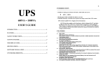
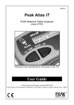
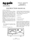
Stark Pool Controller
Service Manual
Page 1
Disassembling a Stark Controller
Referring to Figure 1, open the door of the controller and remove the two screws
retaining the lower access door (labeled “A” in figure). These screws are captive to the
access door. Unplug the power switch assembly at the circuit board inside the controller
and set the access door, switch and fuse assembly aside. Remove the four screws
retaining the bezel (labeled “B” in figure). The bezel may now be removed exposing the
display PCB.
Figure 1
At this level of disassembly, the EPROM chips containing the operating firmware can be
replaced if desired. The new EPROM chips will be marked with “Stark A” and “Stark
B” followed by a version number. The “A” chip goes in the U7 socket and the “B” chip
goes in the U11 socket. The display can be removed by removing the four screws
holding the display to the PCB (these are labeled “B” in figure 2). A socket along the
edge of the display mates with pins on the PCB. Remove the display by pulling straight
out from the PCB to disengage these pins. Take care when installing the new display that
the pins line up with the socket on the display before pressing it firmly down to the PCB.
Also care must be taken not to smudge or scratch the face of the new display. This face
is a very soft plastic and scratches easily. If cleaning is required, use a camera lens cloth
and lens cleaning solution. Potentiometer R26 to the right of the “A” key adjusts the
contrast of the display. This may require adjustment due to component aging or
temperature changes and will certainly require adjustment if the display is replaced.
Page 2
The batteries may also be replaced at this level of disassembly. If still present, cut the tie
wrap that retains the batteries for shipping.
WARNING: Replace the batteries with NiCad rechargeable
batteries only. Replacing with alkaline batteries will
damage the PCB and void the warranty.
When replacing the batteries, it is not necessary to replace the tie wrap. This is required
for shipping only.
To remove the display PCB from the controller, remove the eight retaining screws
labeled “A” in figure 2. Unplug the ribbon cable at the bottom of the PCB (P1). Then
partially raise the PCB and unplug the two-wire cable going to the back of the PCB. This
is the high voltage supply for the florescent backlight of the display.
Figure 2
Page 3
To remove the I/O PCB from the controller refer to figure 3. Reach behind the upper left
corner of the PCB and unplug P1. This plug has a built in retainer that is released by
squeezing in on two ears, one on either side of the connector. While squeezing, rock the
connector from side to side to work the pin contacts loose. Unscrew the two hex standoffs in the center of the PCB (labeled “A” in figure 3). Remove the five screws retaining
the PCB to the chassis (“B” in figure 3). Slide the PCB up toward the top of the chassis
into the area that was occupied by the display PCB. Push the right side of the PCB down
and lift the left side up. There is just enough room to clear the lip on the left side of the
chassis and remove the PCB. Unplug the four cables at the bottom of the PCB (P2, P4,
P3 and P5).
Figure 3
To remove the metal chassis from the controller housing, cut the tie wrap that holds the
pressure transducer wires to the hex stand-off (if present). Remove the four screws at
each corner of the chassis. Lift the chassis out of the housing. The connectors should all
fit through the openings provided in the chassis.
To remove the pressure transducer from the controller housing, remove the five nuts that
hold the pressure transducer block to the housing. It will be necessary to use a Phillips
head screwdriver to hold the back side of these machine screws while the nuts are
removed on the inside. An AMP pin extraction tool is required to remove the connector
from the pressure transducer wires. If this pin extraction tool is not available, cut the
connector off to remove the pressure block from the housing.
Page 4
Assembling a Stark Controller
Install cable assemblies as indicated in figure 4 with a rubber washer on the inside of the
case. The keyway on the connectors should be facing up toward the top of the case. As
viewed from inside of the case as illustrated in figure 5, the two-pin cable P/N 100259 is
on the right. Next install the 8-pin cable P/N 100261. Next install the 5-pin cable P/N
100260. Lastly, the 12-pin cable P/N 100262 should be installed on the left. The plastic
treads on these connectors and retaining nuts are delicate and should not be over
tightened. Use a 13/16” deep socket such as the kind used for spark plugs. Hold the
socket by hand - do not use a socket handle as this will result in too much torque and will
either split the nuts or strip the threads.
The new pressure transducer assembly should come with one stainless steel machine
screw and nut holding the two halves of the transducer block together.
DO NOT REMOVE THIS SCREW!
If the transducer block halves come apart, seals internal to the pressure sensors will be
broken and may result in a leaking transducer assembly.
Figure 4
Place gasket P/N 100445 (see figure 4) against the outside of the case. Place the new
pressure transducer assembly against this gasket feeding the sensor wires through the two
outside holes. Note that one edge of the transducer assembly contains two slots where
the two transducer halves meet. These are safety drains and should be oriented toward
Page 5
the bottom of the case. Install a large fender washer P/N 100456 on the transducer
assembly machine screw protruding through the center hole inside of the case. Tighten a
nut P/N 100246 onto this screw to hold the transducer in place while the other four
retaining screws P/N 100281 are installed and tightened. Wrap quick release fittings P/N
100447 with three wraps of Teflon tape and install into back of transducer block. These
plastic threads are delicate. Follow instructions provided above for tightening the plastic
connectors. The same 13/16” socket will work with these pressure fittings.
Figure 5
Referring to figure 5, twist the pressure sensor wires loosely (about 1 turn per inch) to
reduce electrical noise. Insert these wires into the back of the 8-pin connector body P/N
100158 as follows (pin numbers can be found on the front of the connector body):
Pin 1
Pin 3
Pin 5
Pin 7
Outlet
Outlet
Outlet
Outlet
Brown
Red
Yellow
Orange
Pin 2
Pin 4
Pin 6
Pin 8
Inlet
Inlet
Inlet
Inlet
Brown
Red
Yellow
Orange
Page 6
If all of the outlet wires are installed first, then the inlet wires can be twisted around them
with out worry of confusing inlet and outlet wires at the connector.
Next install the Stark mounting plate P/N 100252. Feed all cables and connectors (5
places) through the cutouts provided in the mounting plate, then affix the plate with four
10-32 by ¼” screws P/N 100257. Tighten the three hex standoffs to the mounting plate.
Use a tie wrap to fasten the transducer assembly wires to the middle standoff. This will
prevent flexing and possible breaking of the pressure transducer leads in the transducer
assembly.
The Stark I/O Subassembly P/N 100087 can now be assembled into the chassis. Plug
cables P2, P4, P3 and P5 into the four connectors along the bottom on the back side of the
PCB. Care must be taken not to confuse the wires coming from the pressure transducer
for P3. P3 comes from the 8 wire circular connector installed in the case. Route the 8wire cable assembly of the pressure transducer between the 5 wire and 8 wire cables of
P4 and P3. This cable will plug into P1 eventually, but if you plug it in now, you will not
be able to maneuver the PCB into the chassis. With the PCB toward the top of the
chassis, lower the right hand side of the PCB past the lip of the chassis and press it clear
to the back of the chassis. The left hand side of the PCB should now just clear the lip on
the left side of the chassis. Once past this lip, the right hand side of the PCB can be
raised to the correct level and the PCB slid down to its mounting position in the bottom
of the chassis. Cables P2 and P4 should be routed along the left side of the chassis,
cables P3 and P5 should be routed along the right side of the chassis, and transducer
cable P1 should come up the middle. Maintain as much separation as possible between
P1 and the other cables to prevent stray noise coupling to the low-level pressure
transducer signal.
Refer to figure 3 of the disassembly instructions and install five screws P/N 100283 in
locations marked “B” in this figure. The transducer assembly cable can now be plugged
into P1 on the back side and to the upper left corner of the I/O subassembly. Be sure that
the retaining mechanism of this connector “snaps” into the locking position or the
connector may vibrate loose resulting in faulty pressure readings.
The I/O subassembly contains six potentiometers that require adjustment if this assembly
has been replaced. Four of these potentiometers are used to match the I/O subassembly
to the pressure transducer subassembly and must be re-adjusted if the pressure transducer
subassembly has been replaced. To access these potentiometers while the Stark
controller is running, the display board must be installed in the “service” position (see
figure 6). Install two hex standoffs P/N 100282 in the location marked “A” in figure 6.
Plug the two-wire cable from the I/O subassembly into the plastic connector on the back
of the display subassembly P/N 100086. Then install the display sub-assembly on these
two standoffs as shown in figure 6. The 26-pin ribbon cable from the I/O subassembly
can now be plugged into P1 on the display subassembly. A power switch assembly P/N
100290 can now be plugged into J2 on the front of the I/O subassembly. The Stark
controller is now ready for calibration.
Page 7
Calibrating a Stark Controller
In the following discussion, all physical parameters are presented in the “English” units
of measurement. The controller should be set to this system of units from the “Display
Parameters” screen. With the display subassembly mounted in the “service” position as
illustrated in figure 6 below, all potentiometers can be accessed for calibration.
Figure 6
To successfully calibrate the pressure sensors, some known pressure supply will be
required. At the factory, air pressure that has been regulated at 50 PSI is used. If no air
pressure is available, city water can be used and calibration values can be scaled to the
actual pressure available.
With the controller running and atmospheric pressure supplied to the inlet and outlet
ports on the pressure transducer at the back of the controller, set R38 and R53 to midrange. Go to the “Inlet Pressure Calibration” screen on the controller (from the main
menu press “System Utilities”, then “Sensor Calibration”, then “Inlet Pressure
Calibration”). Note the line “Current Sensor =”. Adjust R54 for a reading of 150 +/- 5.
This is the “zero” or “offset” adjustment for the inlet sensor amplifier. If this reading will
not adjust to 150, check that the transducer assembly was correctly plugged into P1 on
the I/O subassembly. Now apply 50 PSI to the inlet pressure port at the back of the
Page 8
controller. Adjust R53 for a current sensor reading of 500 +/- 5. R53 is the “span” or
“gain” adjustment for the inlet sensor amplifier. If 50 PSI is not available, any value
between about 30 and 100 PSI may be used. The system should register about 7 counts
per PSI of pressure. For example, if city water pressure is used and is measured at 42
PSI, multiply 42 PSI by 7 counts per PSI to get 294 counts. Add this to the zero offset of
150 counts to get 444. With 42 PSI applied to the inlet port, R53 should be adjusted to
achieve a current sensor reading of 444. There is some interaction between the “offset”
and “span” adjustments so pressure must be removed from the inlet port and R54 must
again be adjusted for a current sensor reading of 150 counts. Then pressure must be
reapplied and R53 readjusted. After two or three iterations, both readings should be
within calibration limits.
This process must be repeated for the outlet pressure sensor with R39 as the “offset”
adjustment and R38 as the “span” adjustment for the outlet pressure amplifier.
Once all of the pressure related potentiometers have been adjusted, the software
calibration procedure described in the “Stark Automatic Pool Controller Operator’s
Manual” can be performed to store the mathematical constants that the controller needs to
convert the “current sensor” values into displayed pressure values.
R56 and R58 are used to calibrate the temperature probe amplifier of the controller. If
temperature monitoring is desired, attach a temperature probe to the system as described
in the diagrams at the back of the “Stark Automatic Pool Controller Operator’s Manual”.
Place this temperature probe in a ice bath made by placing crushed ice and fresh water in
an insulated vessel (a large Styrofoam cup works well). Stir the mixture with the
temperature probe until thermal equilibrium is established. From the temperature
calibration screen, press “123”. This will place you into the “Temperature Zero
Calibration” screen. Ignore the instructions on this screen and adjust R58 for a “current
sensor” reading of 125 +/- 5 counts. Enter 0 degrees from the controller keypad and
press “Enter” to store this value and exit the “Temperature Zero Calibration” screen.
Now press the “Temperature Calibration” key. Place the temperature probe in an
insulated vessel containing 100 degrees F water. Adjust R56 for a “current sensor”
reading of 625 +/- 10 counts. 100 can now be entered from the keypad as the temperature
calibration value. If 100-degree water is not available, the results can again be scaled as
appropriate. The system measures 5 counts per degree F so for 90 degree water, R56
should be adjusted to [(90*5)+125]=575 counts. There should be no interaction between
R58 and R56 so no iteration is required for this calibration.
Once this hardware calibration has been completed, the potentiometers should be
“potted” to prevent vibration or thermal stress from changing their settings. A small dab
of fingernail polish on the top of the potentiometer serves well to prevent movement and
can easily be broken loose should re-calibration be required in the future.
The display subassembly can now be lowered into its correct position. Unscrew the two
screws holding the display subassembly in the “service” position (labeled “A” in figure
6). Remove the two hex standoffs and install them in the two holes marked “A” in figure
3 of the disassembly instructions. The display subassembly can now be installed with
Page 9
eight screws P/N 100283 in locations marked “A” on figure 2 of the disassembly
instructions.
The front bezel can now be installed with four screws P/N 100255 in locations marked
“B” in figure 1 of the disassembly instructions and lower access door can be installed.
Do not over-tighten the screws that hold this door in place. Attempts to tighten these
screws until they stop will result in damage to the access door or to the bezel. These
screws do not have a definite “stop” and should only be tightened enough to hold the
door in position.
If not presently installed, install the housing door using two self-tapping screws. This
completes assembly of the Stark Controller.
Page 10