1
SERVICE MANUAL
Yamaha
ohmmeter leads to t e r m i n a l s .
Resistance should be 0.41-0.51 ohms for
7E1 models or 1.49-1.82 ohms for 7E3
models. Renew stator if desired
resistance readings are not obtained.
OVERHAUL
To disassemble generator, remove end
cover then disconnect and remove control box. Disconnect and remove brush
holder assembly. Unbolt and remove
mounting cushions from stator housing.
Unscrew four through bolts securing
stator housing and remove stator housing. Unscrew rotor through bolt, then
using a slide hammer, break rotor loose
from crankshaft taper and remove
rotor.
Inspect components and reassemble
generator by reversing disassembly procedure. Refer to wiring schematic for
proper wiring connections. Tighten
rotor bolt to 18.6 N-m (14 ft.-lbs.) and
stator through bolts to 7.8 N-m (6
ft.-lbs.).
ENGINE
Model
MF180
Cyls.
1
MF260
1
MAINTENANCE
SPARK PLUG. Recommended spark
plug is a Champion L87Y or NGK BP6HS. Spark plug electrode gap is 0.6-0.7
mm (0.024-0.028 in.).
CARBURETOR. MF180 models are
equipped with a Mikuni BV18-15 carburetor while MF260 models are
equipped with a Keihin BB24-17
carburetor. Initial setting of idle mixture screw is PA turns on BV18-15 carburetor or lVs turns on BB24-17 carburetor. Refer to following tables for carburetor specifications:
Mikuni BV18-15
Fuel inlet valve
Main jet
Pilot air jet
Pilot jet
2.0
.80
3.0
57.5
Keihin BB24-17
Fuel inlet valve
Main air jet
Main jet
Pilot jet
2.0
130
85
40
Bore
65 mm
(2.559 in.)
73 mm
(2.874 in.)
Stroke
54 mm
(2.126 in.)
61 mm
(2.402 in])
IGNITION AND TIMING. All
models are equipped with a capacitor
discharge ignition system. The trigger
coil and charge coil are attached to a
stator plate behind the flywheel while the
ignition module is attached to the fan
housing. Ignition timing is not adjustable.
To check trigger coil and charge coil,
remove fan housing, disconnect coil
leads and remove flywheel. Connect an
ohmmeter to trigger coil lead and coil
base. Ohmmeter should read 603-737
ohms; if not, renew trigger coil. Connect
ohmmeter to charge coil lead and coil
base. Ohmmeter should read 342-418
ohms; if not, renew charge coil. When
reinstalling flywheel, tighten flywheel
nut to 54 N-m (40 ft.-lbs.) on MF180
models or 74 N»m (54 ft.-lbs.) on MF260
models.
Note that an erratic or faulty ignition
system may be due to an oil warning
system malfunction. Refer to
LUBRICATION section.
Displ.
179 cc
(10.9 cu. in.)
256 cc
(15.6 cu. in.)
GOVERNOR. All models are
equipped with a flyweight type governor attached to and driven by the camshaft
gear. The governor forces governor
shaft (S-Fig. Y2-6) to rotate according
to engine speed. Pinch bolt (B) secures
governor arm (G) to shaft (S). Movement
of governor arm (G) is transmitted by
link (L) to carburetor throttle arm.
Note in Fig. Y2-7 that governor spring
end is connected to middle hole (H) of
MF180 governor arm (G) or to lower
hole (H) of MF260 governor arm (G).
To adjust governed speed, loosen
pinch bolt (B - Fig. Y2-6). Pull upper end
of governor arm (G) to left (away from
carburetor) so carburetor throttle is
fully open. Turn governor shaft (S)
counterclockwise until stop is contacted
then retighten pinch bolt (B). With
engine running under no load, turn adjusting screw (W-Fig. Y2-7) so maximum governed speed is 3800 rpm. If
available, a frequency meter may be connected to an outlet and maximum
governed speed adjusted so desired current frequency is obtained.
LUBRICATION. Crankcase capacity
is 680 cc (0.7 qt.) on MF180 models or 950
cc (1.0 qt.) on MF260 models. Use SAE
B
Fig. y2-B—Drawing ot governor linkage. Refer to text for operation.
Fig. Y2-7^Adjust governed engine speed as
outlined fn text. Note position of spring end
in hole (H) for MF1B0 modeis In View A or
for MF2B0 models in View 8.
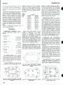
Fig, y2-B—Cross-sectional view of oil level
warning system.
215
GENERATOR
Yamaha
30 oil if ambient temperature is above
15°C (60°F), SAE 20 if temperature is
between 0°C (32°F) and 15°C (6O'*F),
and SAE 10 if temperature is below 0°C
(32°F).
All models are equipped with a low-oil
safety system which disables the ignition
system and lights a warning bulb when
engine oil level is critically low. A float
(F-Fig. Y2-8) mounted in the engine
crankcase monitors oil level aod when
the oil level lowers to less than 325 cc
(0.34 qt.) on MF180 models or to less
than 450 cc (0.48 qt.) on MF260 models,
a magnet in the float closes the contacts
in reed switch (R) thereby grounding the
ignition and lighting the oil warning
light.
Refer to OVERHAUL section to service oil warning system.
OVERHAUL
TIGHTENING TORQUES. Recommended tightening torques are as
follows:
Connecting rod
MF180
MF260
Crankcase cover
MF180
MF260
Cylinder head
lL8N-m
(104 in.-lbs)
15.7 N-m
(139 in.-lbs.)
9.8N-m
(7 ft.-lbs)
17 N-m
(12 ft.-lbs.)
19.6 N-m
(14.5 ft.-lbs)
MF180 models or 0.1-0.3 mm (0.0040.012 in.) on MF260 models. Different
length valves are available if valve tappet gap is incorrect. Valves are marked
"0, 1 or 2". Note valve lengths in following tables:
Valve
Marking
0
1
2
Length
MF180
MF260
91.70104.5591.80 mm
104.65 mm
(3.610(4.1163.614 in.)
4.120 in.)
91.80104.6591.90 mm
104.75 mm
(3.614(4.1203.618 in.)
4.234 in.)
91.90104.7592.00 mm
104.85 mm
(4.124(3.6183.622 in.)
4.128 in.)
Intake valve stem diameter for all
models is 6.955-6.970 mm (0.27380.2744 in.). Exhaust valve stem
diameter is 6.950-6.970 mm (0.27360.2744 in.) on MF180 models or
6.915-6.930 mm (0.2722-0.2728 in.) on
MF260 models. Valve seat width should
be 0.7-0.9 mm (0.027-0.035 in.) for all
valves. Valve spring free length is 33.5
mm (1.319 in.) for MF180 models or 37.0
mm (1.457 in.) for MF260 models.
PISTON, PIN AND RINGS. Piston and
connecting rod are removed as a unit
after cylinder head and crankcase cover
are removed. Piston oversizes available
are 0.25 mm (0.010 in.) and 0.05 mm
Flywheel
MF180
54 N-m
(40 ft.-lbs)
MF260
74 N-m
(54 ft.-lbs.)
CYLINDER HEAD. The cylinder
head is removable. Be sure head gasket
is installed as shown in Fig. Y2-9 or
Y2-10. Tighten cylinder head screws to
19.6 N-m (14.5 ft.-lbs.) in sequence
shown in Fig. Y2-11.
VALVE SYSTEM. Valve tappet gap
is 0.05-0.15 mm (0.002-0.006 in.) on
(0.020 in.). Piston clearance should be
0.085 mm (0.0033 in.) for MF180 models
or 0.070 mm (0.0027 in.) for MF260
models. Piston ring end gap should be
0.2-0.4 mm (0.008-0.016 in.). Install
piston so arrow on crown points towards,
valve side of engine as shown in Fig.
Y2-12. Piston pin is fully floating ir.
piston and rod. Piston pin retaining clips,
should be renewed if removed.
CONNECTING ROD. The connect
ing rod and piston are removed as a unit
after cylinder head and crankcase;
cover are removed. The aluminum rod
rides directly on crankpin. Connecting
rod to crankpin clearance is 0.016-0.034
mm (0.0006-0.0013 in.). Connecting rod
side clearance is 0.2-0.8 mm (0.008-0.032
in.). Match marks (M-Fig. Y2-13) must
be aligned when installing rod. Note that
oil dipper on MF260 models is cast into
rod cap while oil dipper on MF180
models is separate and fits between rod
cap and lock plate as shown in Fig.
Y2-14. Tighten rod screws to 11.8 N-m
(104 in.-lbs.) on MF180 models or to 15.7
N-m (139 in.-lbs.) on MF260 models.
CAMSHAFT AND GOVERNOR.
The camshaft rides directly in crankcase
and crankcase cover. Inspect camshaft
lobes, gear and bearing surfaces for
damage and excessive wear. Crankshaft
and camshaft timing marks must bs
aligned as shown in Fig. Y2-15 during
assembly.
The governor weights, spring and actuating collar are mounted on camshaft
as shown in Fig. Y2-16. Nine governor
weights are held by governor spring on.
MF260 models while only four weights
are used on MF180 models. Be sure cor
lar properly engages groove (G) i:i
weights (W). Install governor fork
(F-Fig. Y2-17) on governor shaft (S) of
MF260 models so pads on fork ends are
towards camshaft.
CRANKSHAFT AND CRANKCASE. The crankshaft is supported by
ball bearings. Inspect crankshaft for e>:cessive wear, straightness and damage.
Fig. y2-iO—Install head gasket on mF2B0
models so tab (T) Is towards flywheel side of
engine.
N
Fig, y2-9—Install head gasket on MF1B0
modeis so notch {N) is towards fiywheel aide
of engine.
216
Fig. y2-11—Tightening sequence for cyiinder
head screws.
Fig. y2-12—install piston so arrow on crown
points towards valves.
Yamaha
SERVICE MANUAL
Crankpin diameter is 24.952-24.970 mm
(0.9824-0.9831 in.) on MF180 models or
28.952-28.970 mm (1.1398-1.1405 in.) on
MF260 models. Tighten crankcase cover
Fig. y2-13—Match marks (M) on side of rod
and cap must be aligned during assembiy.
Fig. y2-1B—Tightening sequence for crankcover screws on MF1B0,
Fig. y2-14—A separate oil dipper {D) is used
on MF1B0 modeis between rod cap (A) and
iock piate (L).
Fig. y2-19—Tightening sequence for crankcase cover screws on MF2B0,
screws to 9.8 N*m (7 ft.-lbs.) on MF180
models or to 17 N-m (12 ft.-lbs.) on
MF260 models. Refer to Fig. Y2-18 or
Y2-19 for tightening sequence.
REWIND STARTER. Refer to Fig.
Y2-20 or Y2-21 for an exploded view of
rewind starter. With starter removed
from engine, untie rope handle from
rope and allow rope to wind into starter
housing. Unscrew nut (1) to disassemble
starter. Use care when removing rope
pulley (13) so rewind spring (15) is not
dislodged from housing (16). If spring
(15) must be removed, use care as uncontrolled uncoiling of spring may cause injury.
When assembling starter, install rewind spring (15) so coil direction is
counterclockwise from outer end. Wind
rope on rope pulley in counter-clockwise
direction as viewed with pulley (13) installed in housing (16). Preload rewind
spring by turning rope pulley two turns
against spring tension before passing
rope through rope outlet in housing.
OIL WARNING SYSTEM. All
models are equipped with an oil warning
system which disables ignition system
when low oil level may damage engine.
See LUBRICATION section.
To inspect oil level assembly, drain
engine oU and remove unit from side of
»
Fig, yz-1S—Align crankshaft and camshaft
timing marks (K) during assembly.
Fig, y2-20—Exploded view
of rewind
starter
on
MF1B0.
Fig, y2-1B—View of MF1B0 governor weights
{W) and spring (S) installed on camshaft gear
(C). MF2B0 assembly is simiiar but more
weights are u$ed. Governor collar is not
shown but must engage groove (G) in
weights.
1.
2.
3.
4.
5.
6.
7.
12.
13.
14.
15.
16.
Fig, y2-21—Exploded view
of rewind
starter
on
MF2B0.
Fig. y2-17—instaii governor fork {F\ on
governor shaft (S) of MF2B0 models with
pads on fork ends towards camshaft.
1.
2.
3.
4.
6.
7.
8.
9.
10.
U.
13.
14.
15.
16.
15 14
Nut
Lockwuher
Washer
Plate
Washer
Return spring
Spring
Pawl assv.
Rope pulley
Plate
Rewind spring
Starter housing
Nut
Lockwasher
Washer
Plate
Return spring
Spring
Washer
Pawl
Spring
Bushing
Rope pulley
Plate
Rewind spring
Starter housing
16
13
14
16
217
Yamaha
GENERATOR
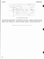
Coupltf
Control box
Fig. Y2-22—Generator wiring schematic.
engine. Handle fioat assembly carefully
as reed switch may be damaged if unit is
dropped. To check operation of fioat
assembly, connect an ohmmeter to
218
mounting flange and to wire lead. Do
not use a continuity tester as battery
may damage reed switch. Ohmmeter
should show continuity with float
assembly in normal position and fioat
hanging down. Ohmmeter should read
infinity with float assembly inverted. Oil
warning light should be checked.