1
5-564.1
5H0806370001
August, 2015
inStallation anD SerVice manual
gas-fired indoor gravity and power vented duct furnaces
models DfG and Dfp
DFP models are approved for use in California by the CEC.
FOR YOUR SAFETY
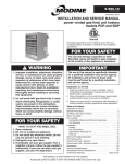
model DfG
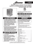
model Dfp
WARNING
1. improper installation, adjustment, alteration,
service or maintenance can cause property
damage, injury or death, and could cause
exposure to substances which have been
determined by various state agencies to
cause cancer, birth defects or other
reproductive harm. read the installation,
operating and maintenance instructions
thoroughly before installing or servicing this
equipment.
2. installing, starting up and servicing heating,
ventilation and air conditioning equipment
poses significant hazards and requires
specialized knowledge of modine products
and training in performing those services.
failure to have any service properly
performed by, or making any modification to
modine equipment without the use of,
qualified service personnel could result in
serious injury to person and property,
including death. therefore, only qualified
service personnel should work on any
modine products.
if You Smell GaS:
1. open windows.
2. Don’t touch electrical switches.
3. extinguish any open flame.
4. immediately call your gas supplier.
FOR YOUR SAFETY
the use and storage of gasoline or other
flammable vapors and liquids in open
containers in the vicinity of this appliance is
hazardous.
inspection on arrival
1. Inspect unit upon arrival. In case of damage, report it
immediately to transportation company and your local factory
sales representative.
2. Check rating plate on unit to verify that power supply meets
available electric power at the point of installation.
3. Inspect unit upon arrival for conformance with description of
product ordered (including specifications where applicable).
CAUTION
to prevent premature heat exchanger failure
do not locate anY gas-fired units in areas
where chlorinated, halogenated, or acid vapors
are present in the atmosphere.
THIS MANUAL IS THE PROPERTY OF THE OWNER.
PLEASE BE SURE TO LEAVE IT WITH THE OWNER WHEN YOU LEAVE THE JOB.
5-564.1
special precautions / table of contents
Special Precautions
THE INSTALLATION AND MAINTENANCE INSTRUCTIONS
IN THIS MANUAL MUST BE FOLLOWED TO PROVIDE SAFE,
EFFICIENT AND TROUBLE-FREE OPERATION. iN ADDITION,
PARTICULAR CARE MUST BE EXERCISED REGARDING
THE SPECIAL PRECAUTIONS LISTED BELOW. FAILURE
TO PROPERLY ADDRESS THESE CRITICAL AREAS COULD
RESULT IN PROPERTY DAMAGE OR LOSS, PERSONAL
INJURY, OR DEATH. THESE INSTRUCTIONS ARE SUBJECT
TO ANY MORE RESTRICTIVE LOCAL OR NATIONAL CODES.
HAZARD INTENSITY LEVELS
1. DANGER: Indicates an imminently hazardous situation which,
if not avoided, WILL result in death or serious injury.
2. WARNING: Indicates a potentially hazardous situation which, if
not avoided, COULD result in death or serious injury.
3. CAUTION: Indicates a potentially hazardous situation which,
if not avoided, MAY result in minor or moderate injury.
4. Important: Indicates a situation which, if not avoided,
MAY result in a potential safety concern.
DANGER
Appliances must not be installed where they may be
exposed to a potentially explosive or flammable atmosphere.
WARNING
1. Gas fired heating equipment must be vented - do not operate
unvented.
2. a. Model DFG has a built-in draft diverter - additional external
diverters are not required or permitted.
b. Model DFP has a built-in power exhauster - additional
external power exhausters are not required or permitted.
3. If you are replacing an existing heater, it may be necessary to
resize the venting systems. Improperly sized venting systems
can result in vent gas leakage or the formation of condensate.
Refer to the National Fuel Gas Code ANSI Z223.1 or CSA
B149.1 latest edition. Failure to follow these instructions can
result in injury or death.
4.For Model DFG, gas-fired heating equipment which has been
improperly vented, or which experiences a blocked vent
condition may have flue gases accidentally spilled into the
heated space. See page 22 for specific information about the
blocked vent safety switch supplied on the unit.
5. For Model DFP, under no circumstances should two sections
of double wall vent pipe be joined together within one
horizontal vent system due to the inability to verify complete
seal of inner pipes.
6. All field gas piping must be pressure/leak tested prior to operation. Never use an open flame. Use a soap solution or equivalent for testing.
7. Gas pressure to appliance controls must never exceed 14"
W.C. (1/2 psi).
8. Disconnect power supply before making wiring connections
to prevent electrical shock and equipment damage.
9.All appliances must be wired strictly in accordance with wiring diagram furnished with the appliance. Any wiring different from the wiring diagram could result in a hazard to persons and property.
10.To reduce the opportunity for condensation, the minimum sea level input to the appliance, as indicated on the serial plate, must not be less than 5% below the rated input, or 5% below the minimum rated input of duel rated units.
11. E
nsure that the supply voltage to the appliance, as indicated
on the serial plate, is not 5% greater than the rated voltage.
12. Any original factory wiring that requires replacement must be
replaced with wiring material having a temperature rating of at
least 105°C.
13. When servicing or repairing this equipment, use only factoryapproved service replacement parts. A complete replacement
parts list may be obtained by contacting Modine
Manufacturing Company. Refer to the rating plate on the
appliance for complete appliance model number, serial
number, and company address. Any substitution of parts or
controls not approved by the factory will be at the owners risk.
2
CAUTION
1. Purging of air from gas lines should be performed as described
in ANSI Z223.1 - latest edition “National Fuel Gas Code”, or in
Canada in CAN/CGA-B149 codes.
2. Do not attempt to reuse any mechanical or electrical
controllers which have been wet. Replace defective controller.
3. Ensure that the supply voltage to the application, as indicated
on the serial plate, is not 5% less than the rated voltage.
important
1. To prevent premature heat exchanger failure, do not locate
ANY gas-fired appliances in areas where corrosive vapors
(i.e. chlorinated, halogenated or acid) are present in the
atmosphere.
2. To prevent premature heat exchanger failure, the input to the
appliance, as indicated on the serial plate, must not exceed the
rated input by more than 5%.
3. To prevent premature heat exchanger failure, observe heat
exchanger tubes by looking at the heat exchanger through field
installed access openings in connecting ductwork. If the bottom
of the tubes become red while blower and duct furnace are in
operation, additional baffles must be inserted between blower
and duct furnace to assure uniform air flow across the heat
exchanger.
4. To prevent premature heat exchanger failure, with all control
systems, a blower starting mechanism must be provided so
that the blower is running or energized within 45 seconds of the
gas control operation.
5. S
tart-up and adjustment procedures should be performed by a
qualified service agency.
6. To check most of the Possible Remedies in the troubleshooting
guide listed in Table 20.1, refer to the applicable sections of
the manual.
Table of Contents
Inspection on Arrival...............................................................................1
Special Precautions................................................................................2
SI (Metric) Conversion Factors...............................................................3
Unit Location..........................................................................................3
Location Recommendations...........................................................3
Combustible Material and Service Clearances..............................3
Combustion Air Requirements........................................................3
Unit Suspension.....................................................................................4
Installation..............................................................................................4
Direction of Airflow..........................................................................4
Air Distribution Baffle Removal.......................................................4
Duct Installation and Airflow Distribution.....................................4-5
Venting........................................................................................5-7
Gas Connections............................................................................8
Considerations for Elevation..........................................................9
Electrical Connections..................................................................10
Start-Up Procedure..............................................................................10
Pilot Burner and Main Burner Adjustment.................................... 11
Air Shutter Adjustment..................................................................12
Control Operating Sequence...................................................12-13
Variable Air Movement Applications.............................................13
Options.................................................................................................14
Performance.........................................................................................15
Air Temperature Rise Limits.........................................................15
Recommended Unit Configurations.............................................15
Pressure Drop Curves..................................................................15
Dimensional Data............................................................................16-17
Maintenance....................................................................................18-19
Service & Troubleshooting..............................................................20-22
Replacement Parts Ordering................................................................23
Model Identification..............................................................................24
Commercial Warranty..............................................................Back Page
5-564.1
si (metric) conversion factors / unit location
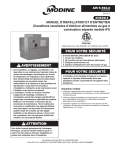
Figure 3.1 - Combustible Material and Service
Clearances
SI (Metric) Conversion Factors
Table 3.1
To ConvertMultiply ByTo Obtain
"W.C.
0.24
kPa
psig
6.893
kPa
°F
(°F-32) x 0.555
°C
inches
25.4
mm
feet
0.305 meters
CFM
0.028
m3/min
To ConvertMultiply ByTo Obtain
CFH
1.699 m3/min
Btu/ft3 0.0374mJ/m3
pound
0.453
kg
Btu/hr 0.000293 kW/hr
gallons
3.785
liters
psig
27.7
"W.C.
Unit Location
danger
Appliances must not be installed where they may be exposed
to a potentially explosive or flammable atmosphere.
important
Model DFG
Model DFP
➀A 3'' minimum clearance to combustible material is required from the vent collar.
Table 3.2 - Combustible Material Clearances
To prevent premature heat exchanger failure, do not locate
ANY gas-fired appliances in areas where corrosive vapors (i.e.
chlorinated, halogenated or acid) are present in the atmosphere.
Location Recommendations
1. When locating the furnace, consider general space and
heating requirements, availability of gas and electrical
supply, and proximity to vent locations.
2. Unit must be installed on the positive pressure side of the
circulating blower.
3. Be sure the structural support at the unit location site is
adequate to support the weight of the unit. For proper
operation the unit must be installed in a level horizontal
position.
4. Do not install units in locations where the flue products
can be drawn into the adjacent building openings such as
windows, fresh air intakes, etc.
5. Be sure that the minimum clearances to combustible
materials and recommended service clearances are
maintained. Units are designed for installation on noncombustible surfaces with the minimum clearances shown
in Figure 3.1 and Tables 3.2 and 3.3.
6. Units installed downstream of refrigeration systems, or
exposed to inlet air temperatures of 40°F or less, may
experience condensation, therefore, provisions should
be made for disposal of condensate. Means have been
provided in the bottom pan of the unit to accommodate a
condensate drain line connection flange.
7. When locating units, it is important to consider that the
exhaust vent piping must be connected to the outside
atmosphere.
8. In garages or other sections of aircraft hangars such as
offices and shops which communicate with areas used for
servicing or storage, keep the bottom of the unit at least 7”
above the floor. In public garages, the unit must be installed
in accordance with the Standard for Parking Structures
NFPA #88A and the Standard for Repair Garages NFPA
#88B. In Canada, installation of unit heaters in airplane
hangars must be in accordance with the requirements of
the enforcing authority, and in public garages in accordance
with the current CAN/CGA-B149 codes.
9. Do not install units in locations where gas ignition system is
exposed to water spray, rain, or dripping water.
5-564.1
Access Side Non-Access
(A)
Side (B)
Top
(C)
Bottom
(D)
Model Size
DFG
DFP
All
DFG
DFP
All
75 thru 175
6"
12"
1"
2"
3"
2"
200 thru 400
6"
12"
2"
2"
3"
2"
Table 3.3 - Recommended Service Clearances
Model Size
Access Side Non-Access
(A)
Side (B)
75
18"
100/125
20"
150/175
25"
200/225
27"
250/300
30"
350/400
41"
6"
Top
(C)
Bottom
(D)
10"
0"
Combustion Air Requirements
Units installed in tightly sealed buildings or confined spaces
must be provided with two permanent openings, one near
the top of the confined space and one near the bottom. Each
opening should have a free area of not less than one square
inch per 1,000 BTU per hour of the total input rating off all
units in the enclosure, freely communicating with interior areas
having, in turn adequate infiltration from the outside.
For further details on supplying combustion air to a confined
(tightly sealed) space or unconfined space, see the National
Fuel Gas Code ANSI Z223.1 of CAN/CGA B149.1 or .2
Installation Code, latest edition.
3
unit SUSPENSION / installation
Air Distribution Baffle Removal
UNIT SUSPENSION
Be sure the means of suspension is adequate to support the
weight of the unit (see Dimensional Data for unit weights). For
proper operation, the unit must be installed in a level horizontal
position. Combustible material and service clearances as
specified in Figure 3.1 and Tables 3.2 and 3.3 must be strictly
maintained.
1. Four 1/2" - 13NC tapped holes in top of furnace are provided
to accept ceiling hangers. To assure that flames are directed
into the center of the heat exchanger tubes, the furnace must
be supported in a vertical position. Use a spirit level to ensure
that unit is suspended correctly.
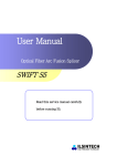
2. NOTE: A pipe hanger adapter kit, shown in Figure 4.1, is
available as an accessory. One kit consists of two drilled
3/4" IPS pipe caps and two 1/2 - 13 x 1-3/4" capscrews to
facilitate threaded pipe suspension. Two kits are required for
mounting all duct furnace models.
Figure 4.1 - Suspension Methods
The duct furnaces are supplied with a factory installed air baffle.
For applications where an air temperature rise less than 60°F
is desired, it is recommended to remove this baffle to reduce
system pressure drop. Refer to Figures 15.2 and 15.3.
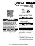
Duct Installation
1. The furnace is designed to accept straight ductwork. See
Figure 4.3. Provide an airtight seal between the ductwork
and the furnace. Seams with cracks in ductwork should be
caulked and/or taped and be of permanent type. All duct
connections MUST be airtight to prevent air leakage.
2. P
rovide removable access panels on both the upstream and
downstream sides of the ductwork; see Figure 4.3. These
openings should be large enough to view smoke or reflect
light inside the casing to indicate leaks in the heat exchanger
and to check for hot spots on heat exchangers due to poor air
distribution or lack of sufficient air (CFM)
Figure 4.3 - Duct Connections
c
(Threaded Rod)
(Pipe Adapter Kit)
INSTALLATION
Direction of Airflow
Select proper direction of airflow. The air baffle must face the
air inlet direction as shown in Figure 4.2. If it is necessary to
reverse the airflow direction, remove the four screws securing
the air distribution baffle, reverse the air distribution baffle to the
air inlet side and replace the screws. See Airflow Reversal Note.
Figure 4.2 - Air Distribution Baffle Location
Airflow Distribution
important
Baffle location shown on entering air side of duct furnace.
To prevent premature heat exchanger failure, observe heat
exchanger tubes by looking at the heat exchanger through
field installed access openings in connecting ductwork. If
the bottom of the tubes become red while blower and duct
furnace are in operation, additional baffles must be inserted
between blower and duct furnace to assure uniform air flow
across the heat exchanger.
air
distribution
baffle
Airflow Reversal Note: If factory installed discharge air options
(thermostat, freeze protection, etc.) were provided, these
options would have to be relocated to the discharge air side of
the duct furnace.
4
1. P
rovide uniform air distribution over the heat exchanger.
Use turning vanes where required (see Figure 5.1) to obtain
uniform air distribution. Avoid installing as in “G”, “H” & “J” of
Figure 5.1.
2. A bottom, horizontal discharge type blower should be
installed at least 12" from the furnace (See “A”, Figure 5.1).
3. A top, horizontal discharge type blower should be installed at
least 24" from the furnace (See “B”, Figure 5.1). Provide air
baffle at top of duct to deflect air down to the bottom of heat
exchanger.
5-564.1
installation
Figure 5.1 - Typical Duct & Airflow Installation
RECOMMENDED INSTALLATIONS
A
B
D
A
SIDE
Baffle
3" Max.
Turning
Vanes
24"
Min.
SIDE
G
INSTALLATIONS
NOT RECOMMENDED
15° Max.
Dimensions “B” should never be less than 1/2 of “A”.
F
Vanes
3" Max.
15° Max.
Baffle
TOP
E Turning
B
A
12"
Min.
A
24"
Min.
12"
Min.
Air
Baffle
B
SIDE
Baffle
12"
Min.
12"
Min.
A
C
Air
Baffle
12"
Min.
Turning
Vanes
SIDE
B
3" Min.
B
3" Max.
B
3" Max.
A
Turning
Vanes
3" Min.
Turning
Vanes
12"
Min.
TOP
3" Min.
Turning
Vanes
Turning
Vanes
15° Max.
H
SIDE
J
SIDE
No Air
TOP
No Air
VENTING
No Air
Table 5.1 - Venting Category Determination
WARNING
1. Gas fired heating equipment must be vented - do not
operate unvented.
2. a. Model DFG has a built-in draft diverter - additional external diverters are not required or permitted.
b. Model DFP has a built-in power exhauster - additional
external power exhausters are not required or permitted.
3. If you are replacing an existing heater, it may be necessary to
resize the venting systems. Improperly sized venting systems
can result in vent gas leakage or the formation of condensate.
Refer to the National Fuel Gas Code ANSI Z223.1 or CSA
B149.1 latest edition. Failure to follow these instructions can
result in injury or death.
4.For Model DFG, gas-fired heating equipment which has been
improperly vented, or which experiences a blocked vent
condition may have flue gases accidentally spilled into the
heated space. See page 22 for specific information about the
blocked vent safety switch supplied on the unit.
5. For Model DFP, under no circumstances should two sections of
double wall vent pipe be joined together within one horizontal
vent system due to the inability to verify complete seal of inner
pipes.
General Venting Instructions
1.Installation of venting must conform with local building codes,
or in the absence of local codes, with the National Fuel Gas
Code, ANSI Z223.1 (NFPA 54) - Latest Edition. In Canada,
installation must be in accordance with CAN/CGA-B149.1 for
natural gas units and CAN/CGA-B149.2 for propane units.
2. To determine the Venting Category of the unit being installed,
refer to Table 5.1.
Model
Venting
Category
DFG
I➀
Vertically vented units only.
I➀
Vertically vented units only.
III ➁
Horizontally vented units only.
DFP
Vent Configuration
➀ Vent is negative pressure, non-condensing. Follow standard venting requirements.
➁ Vent is positive pressure, non-condensing. Vent must be gastight.
3.For units vented as Category I, refer to Table 5.2 for vent
sizing. Vent sizing for units vented as Category III are covered
in a later section on page 7. Do not use a vent pipe smaller
than the size of the outlet or vent transition of the appliance.
The pipe should be suitable corrosion resistant material.
Follow the National Fuel Gas Code for minimum thickness
and composition of vent material. The minimum thickness for
connectors varies depending on the pipe diameter.
Table 5.2 - Category I Minimum Vent Pipe Diameter
Minimum Vent Pipe Diameter
Model
Size
DFG
DFP
75
5"
4"
100-125
6"
4"
150-175
7"
5" j
200-225
7"
6"
250
8"
6"
300-400
10"
6"
➀ Requires a 4" to 5" adapter for the larger vent pipe diameter.
5-564.1
5
VENTING
4.For Category I vent systems limit length of horizontal runs to
75% of vertical height. Install with a minimum upward slope
from unit of 1/4 inch per foot and suspend securely from
overhead structure at points no greater than 3 feet apart.
For best venting, put vertical vent as close to the unit as
possible. For Model DFP units, a minimum of 12" straight
pipe is recommended from the power exhauster outlet before
turns in the vent system. Fasten individual lengths of vent
together with at least three corrosion-resistant sheet-metal
screws.
5.It is recommended that vent pipes be fitted with a tee with a
drip leg and a clean out cap to prevent any moisture in the
vent pipe from entering the unit. The drip leg should be inspected
and cleaned out periodically during the heating season.
6.The National Fuel Gas Code requires a minimum clearance
of 6 inches from combustible materials for single wall vent
pipe. The minimum distance from combustible materials is
based on the combustible material surface not exceeding
160°F. Clearance from the vent pipe (or the top of the unit)
may be required to be greater than 6 inches if heat damage
other than fire (such as material distortion or discoloration)
could result.
7.Avoid venting through unheated space. When venting does
pass through an unheated space, insulate runs greater than
5 feet to minimize condensation. Inspect for leakage prior to
insulating and use insulation that is noncombustible with a
rating of not less than 350°F. Install a tee fitting at the low
point of the vent system and provide a drip leg with a clean
out cap as shown in Figure 6.1.
8.When the vent passes through a combustible wall or floor, a
metal thimble 4 inches greater than the vent diameter is
necessary. If there is 6 feet or more of vent pipe in the open
space between the appliance and where the vent pipe
passes through the wall or floor, the thimble need only be 2
inches greater than the diameter of the vent pipe. If a thimble
is not used, all combustible material must be cut away to
provide 6 inches of clearance. Any material used
to close the opening must be noncombustible.
9. Do NOT use dampers or other devices in the vent pipes.
10. Precautions must be taken to prevent degradation of building materials by flue products.
11.For category I vent systems the outlet of the vent should
extend as shown in Figure 6.1 and Tables 6.1 and 6.2.
12.Use a listed vent terminal to reduce downdrafts and moisture
in vent. For model DFG, a vent terminal that is very open will
avoid spillage at unit’s diverter relief opening and tripping of
the blocked vent safety switch.
13.For instructions on common venting refer to the National
Fuel Gas Code.
14.The vent must terminate no less than 5' above the vent
connector for Category I vent systems.
15.A unit located within an unoccupied attic or concealed space
shall not be vented with single wall vent pipe.
16.Single wall vent pipe must not pass through any attic, inside
wall, concealed space, or floor.
17. Do NOT vent Model DFP units into a masonry chimney.
Model DFG units can be vented into a masonry chimney if
the following requirements are met:
a. Do not vent a Category l unit into a common vent with
mechanical draft systems operating under positive
pressure (Category lll or lV units.)
b. When connecting a vent to an existing chimney, do not
push the vent pipe beyond internal surface of chimney.
c. When venting into a common vent, the area of the
common vent should be equal to or greater than the
area of the largest vent plus 50 percent of the area of all
additional vents.
d. When venting into a common vent, the individual vents
should enter at different levels.
6
Figure 6.1 - Vertical Category I Vent System
10 FEET OR LESS
TO ROOF PEAK
LISTED
TERMINAL
2 FEET MINIMUM
"H" FEET MINIMUM
PER TABLE 6.1
X
ROOF PITCH IS:
X / 12
12"
ROOF
FLASHING
USE LISTED
THIMBLE
THROUGH
ROOF
MAINTAIN MINIMUM
CLEARANCE TO
COMBUSTIBLES
USE LISTED
THIMBLE
THROUGH
CEILING
TEE WITH DRIP LEG
AND CLEANOUT CAP
12" MINIMUM
(SLOPE PIPE UP
1/4" PER FOOT
TOWARD DRIP LEG)
DISTANCE "D" TO
WALL OR ADJOINING
BUILDING
LISTED
TERMINAL
"H" FEET MINMUM
ABOVE WALL OR
ADJOINING
BUILDING PER
TABLE 6.2
3 FEET
MINIMUM*
ROOF
FLASHING
* SIZE ACCORNING
TO EXPECTED
SNOW DEPTH.
MAINTAIN MINIMUM
CLEARANCE TO
COMBUSTIBLES
USE LISTED
THIMBLE
THROUGH
CEILING
TEE WITH DRIP LEG
AND CLEANOUT CAP
12" MINIMUM
(SLOPE PIPE UP
1/4" PER FOOT
TOWARD DRIP LEG)
Table 6.1 - Minimum Height from Roof to Lowest
Discharge Opening
Roof Rise
“X” (in)
0-10
10-12
12-14
14-16
16-18
18-21
Equivalent
Roof Pitch
Minimum Height
“H” (ft) j
Flat to 10/12
10/12 to 12/12
12/12 to 14/12
14/12 to 16/12
16/12 to 18/12
18/12 to 21/12
3.00
4.00
5.00
6.00
7.00
8.00
j Increase "H" as required to accommodate snow depth.
Table 6.2 - Minimum Height Above Adjacent Wall
Less than 10 Feet Away
"D"
"H"
10 Feet or Less
2 Feet Minimum
Greater than 10 Feet
No Additional Height Required
5-564.1
VENTING
18. When condensation may be a problem, the venting system shall not terminate over public walkways or over an area where condensation or vapor could create a nuisance or hazard or could be detrimental to the operation of regulator
relief openings or other equipment.
19. In cold ambient conditions, such as Canada, the following items are recommended for proper operation and equipment life:
• The vent pipe must not pass through an unheated space or interior part of an open chimney unless the vent pipe is insulated.
• Where the vent pipe may be exposed to extreme cold, or come into contact with snow or ice, the entire vent must
be insulated or double wall (includes outdoors). It is
preferred that the double wall vent is one continuous
piece but a joint is allowed outside the building.
• The heater system shall be checked at least once a year by a qualified service technician.
Additional Requirements for Horizontally Vented
Category III Units (Model DFP units only)
1.Seal the joints with a metallic tape or silastic suitable for temperatures up to 350°F. (3M tapes 433 or 363 are acceptable.) Wrap tape two full turns around the vent pipe.
2.Refer to Table 7.1 for total minimum and maximum vent lengths making the vent system as straight as possible.
The equivalent length of a 90° elbow is 5 feet for 4" diameter
and 7 feet for 6" diameter.
Table 7.1 - Horizontal Category III Vent Sizing
Requirements
Model Size
75
100-175
200
225
250-300
350-400
Vent Connector Minimum Vent
Diameter
Pipe Diameter
4"
4"
6"
6"
6"
6"
4"
4"
5" ➀
6"
6"
6"
Maximum
Vent Length
➀U
nit can be vented with 5" diameter pipe if a 6" to 5" reducer is used.
Otherwise, use 6" pipe.
48'
55'
70'
70'
63'
70'
3.The vent terminal must be Modine part number:
• 5H072285-0001 (Item Code 27866) for 4" vent pipe
• 5H072285-0004 (Item Code 27867) for 5" vent pipe
• 5H072285-0002 (Item Code 27868) for 6" vent pipe
A Gary Steel 1092 cap is an acceptable alternate.
4.The vent must extend a minimum of 12" beyond the exterior
wall surface and must be supported as shown in Figure 7.1.
Precautions must be taken to prevent degradation of building
materials by flue products.
5. The vent system shall terminate at least 3 feet above any forced air inlet (except direct vent units) located within 10 feet,
and at least 4 feet below, 4 feet horizontally from, or 1 foot
above any door, window, or gravity air inlet into any building.
The bottom of the vent terminal shall be located above the
snow line or at least 1 foot above grade; whichever is greater.
When located adjacent to public walkways the vent system
shall terminate not less than 7 feet above grade.
6. The venting system must be exclusive to a single unit, and no other unit is allowed to be vented into it.
7.Horizontally vented units must use single wall vent pipe
although one continuous section of double wall vent pipe
may be used with the vent system. Under no circumstances
should two sections of double wall vent pipe be joined
together within one vent system due to the inability to verify
complete seal of inner pipes.
Figure 7.1 - DFP Horizontal Venting
MODEL DFP
UNIT
USE LISTED THIMBLE
THROUGH WALL
(SLOPE PIPE DOWN
1/4" PER FOOT
TOWARD DRIP LEG)
12" MIN
SPECIFIED
TERMINAL
9" MIN
9" MIN
TEE WITH DRIP LEG
AND CLEANOUT CAP
5-564.1
STEEL ANGLE
VENT TERMINATION
SUPPORT BRACKET
(WHERE REQUIRED)
7
installation
Gas Connections
warning
Figure 8.1 - Recommended Sediment Trap/Manual
Shut-off Valve Installation - Side or Bottom Gas
Connection
1. All field gas piping must be pressure/leak tested prior to
operation. Never use an open flame. Use a soap solution or
equivalent for testing.
2. Gas pressure to appliance controls must never exceed 14"
W.C. (1/2 psi).
3. To reduce the opportunity for condensation, the minimum sea
level input to the appliance, as indicated on the serial plate,
must not be less than 5% below the rated input, or 5% below
the minimum rated input of duel rated units.
caution
Purging of air from gas lines should be performed as
described in ANSI Z223.1 - latest edition “National Fuel Gas
Code”, or in Canada in CAN/CGA-B149 codes.
IMPORTANT
To prevent premature heat exchanger failure, the input to the
appliance, as indicated on the serial plate, must not exceed
the rated input by more than 5%.
1. Installation of piping must conform with local building codes,
or in the absence of local codes, with the National Fuel Gas
Code, ANSI Z223.1 (NFPA 54) - Latest Edition. In Canada,
installation must be in accordance with CAN/CGA-B149.1 for
natural gas units and CAN/CGA-B149.2 for propane units.
2. P
iping to units should conform with local and national
requirements for type and volume of gas handled, and
pressure drop allowed in the line. Refer to Table 8.1 to
determine the cubic feet per hour (cfh) for the type of gas
and size of unit to be installed. Using this cfh value and the
length of pipe necessary, determine the pipe diameter from
Table 8.2. Where several units are served by the same main,
the total capacity, cfh and length of main must be considered.
Avoid pipe sizes smaller than 1/2". Table 8.2 allows for a 0.3"
W.C. pressure drop in the supply pressure from the building
main to the unit. The inlet pressure to the unit must be 6-7"
W.C. for natural gas and 11-14" W.C. for propane gas. When
sizing the inlet gas pipe diameter, make sure that the unit
supply pressure can be met after the 0.3" W.C. has been
subtracted. If the 0.3" W.C. pressure drop is too high, refer to
the Gas Engineer’s Handbook for other gas pipe capacities.
3. The gas piping to the unit can enter the unit from the side of
the unit or from below. Install a ground joint union with brass
seat and a manual shut-off valve external of the unit casing,
and adjacent to the unit for emergency shut-off and easy
servicing of controls, including a 1/8" NPT plugged tapping
accessible for test gauge connection (See Figure 8.1).
4. P
rovide a sediment trap before each unit in the line where low
spots cannot be avoided. (See Figure 8.1).
5. W
hen Pressure/Leak testing, pressures above 14" W.C. (1/2
psi), close the field installed shut-off valve, disconnect the
appliance and its combination gas control from the gas supply
line, and plug the supply line before testing. When testing
pressures 14" W.C. (1/2 psi) or below, close the manual shutoff valve on the appliance before testing.
➀
➀M
anual shut-off valve is in the “OFF” position when handle is perpendicular to
pipe.
Table 8.1 - Burner Orifice Sizing and Gas Consumption
Gas Type
Model
Size
75
100
125
150
175
200
225
250
300
350
400
Cfh
Orifice Drill Size
Cfh
Orifice Drill Size
Cfh
Orifice Drill Size
Cfh
Orifice Drill Size
Cfh
Orifice Drill Size
Cfh
Orifice Drill Size
Cfh
Orifice Drill Size
Cfh
Orifice Drill Size
Cfh
Orifice Drill Size
Cfh
Orifice Drill Size
Cfh
Orifice Drill Size
Natural ➀
Propane ➁
72.1
20
96.1
30
120.2
25
144.2
30
168.3
27
192.3
23
216.3
20
240.4
25
288.7
20
336.5
27
384.6
23
30.0
39
40.0
45
50.0
42
60.0
45
70.0
43
80.0
42
90.0
39
100.0
42
120.0
39
140.0
43
160.0
42
Orifice Qty
1
2
2
3
3
3
3
4
4
6
6
➀ Based on natural gas properties of 1040 Btu/Cu. Ft. and specific gravity of 0.60.
➁ Based on propane gas properties of 2500 Btu/Cu. Ft. and specific gravity of 1.53.
Table 8.2 - Gas Pipe Capacities - Natural Gas ➀
Pipe
Length (ft)
10
20
30
40
1/2"
132
92
73
3/4"
278
190
152
Natural Gas
1"
520
350
285
1-1/2"
730
1100
1050
590
890
130
50
105
80
43
90
170
350
530
125
34
72
130
275
410
60
70
100
150
56
46
38
31
115
96
79
64
215
195
180
150
120
500
1600
63
50
245
1-1/4"
440
400
370
305
250
760
2"
3050
2100
1650
1450
670
1270
560
1050
460
870
610
380
1150
930
780
710
C
apacities in Cubic Feet per Hour through Schedule 40 pipe with maximum
0.3" W.C. pressure drop with up to 14" W.C. gas pressure. Specific gravity is 0.60
for Natural gas and 1.50 for Propane gas.
F
or Pipe Capacity with Propane Gas, divide Natural gas capacity by 1.6. Example:
What is the Propane gas pipe capacity for 60 feet of 1-1/4" pipe? The Natural gas
capacity is 400 CFH. Divide by 1.6 to get 250 CFH for Propane gas.
8
5-564.1
installation
Considerations for Elevation
The standard ratings for Models DFG and DFP are certified for
elevations up to 2000 feet above sea level. Operation at
elevations above 2,000 feet requires ratings be reduced 4% for
each 1000 feet above sea level per ANSI Z223.1. The exception
is for units in Canada, CSA requires that ratings be reduced 10%
for elevations between 2,001 and 4500 feet. The following
instructions are for units that will be installed over 2,000 feet
elevation. If this does not apply, you may skip ahead to the
Electrical Connections section on page 10.
Manifold Pressure Adjustment
• For Natural Gas units, 3.5" W.C. based on a gas heating value
of 1,050 BTU/ft3.
• For Propane Gas units, 10.0" W.C. based on a gas heating
value of 2,500 BTU/ft3.
For higher elevations, some utility companies may derate the
BTU content (heating value) of the gas provided at altitude to a
lower value to allow certain heating appliances to be used with
no manifold pressure adjustments. For this reason it is necessary
that the supplying utility be contacted for detailed information
about the gas type and BTU content (heating value) before
operating any heater. Table 9.1 shows the standard derated
heating values of natural and propane gases at various
elevations.
Table 9.1
Gas Heating Values at Altitude (Btu/ft3) ➀ ➁ ➂ ➄
0-2,000
2,001-3,000
3,001-4,000
4,001-4,500
4,501-5,000
5,001-6,000
6,001-7,000
7,001-8,000
8,001-9,000
9,001-10,000
Natural Gas
Propane
1,050
929 ➂
892 ➂
874 ➂
856
822
789
757
727
698
2,500
2212 ➃
2123 ➃
2080 ➃
2,038
1,957
1,879
1,803
1,731
1,662
Where:
MPELEV = Manifold Pressure (" W.C.) at installed
elevation
BTUTBL = BTU/ft3 content of gas from Table 9.1
The unit manifold pressure is factory set for operation at
elevations up to 2000 feet as follows:
Altitude (ft)
Equation 9.1 - Manifold Pressure for Gas Heating
Values Different Than Shown in Table 9.1
BTUACT = BTU/ft3 content of gas obtained from the
utility company
MPSL = Manifold Pressure (" W.C.), at Sea Level
(use 3.5" W.C. for natural gas and
10.0" W.C. for propane)
NOTE: For units equipped with two-stage or modulating gas
controls, only the high fire manifold pressure needs to be
adjusted. No adjustments to the low fire manifold pressure are
necessary on these units.
Selection of the Proper High Altitude Kit
All units installed at elevations greater than 2000 feet above sea
level require a kit, in addition to potential manifold pressure
adjustment outlined in the previous step. To determine the proper
kit to use, refer to Table 9.2.
Table 9.3 shows the contents of the kit. For more information,
refer to the latest revision of Modine Bulletin 75-530.
Table 9.2 - High Altitude Kit Selection Table ➀ ➁
Model
DFG
DFP
➀ Values shown are for 3.5" W.C. manifold pressure for Natural Gas and 10.0"
W.C. for Propane Gas. If the local utility supplies gas with a different Btu/ft3
value, use Equation 9.1 to calculate the required manifold pressure.
➁ Gas heating values shown are derated 4% per 1,000' of elevation (10%
between 2,000' and 4,500' elevation in Canada) in accordance with ANSI
Z223.1 and CSA-B149, respectively.
➂ 945 Btu/ft3 for Canada
➃ 2,250 Btu/ft3 for Canada
➄ When installed at altitudes above 2,000', a pressure switch may need to be
changed. Refer to Tables 9.2 and 9.3 to determine if a switch change is
required.
If the utility is supplying gas with heating values SAME as shown
in Table 9.1, the manifold pressure should remain set to 3.5"
W.C. for natural gas and 10.0" W.C. for propane gas and you
may proceed to the section on this page titled “Selection of the
Proper High Altitude Kit”.
If the utility is supplying gas with heating values DIFFERENT
than shown in Table 9.1, use Equation 9.1 to determine the
appropriate manifold pressure for the elevation and gas heating
value being supplied. Note what that value is, as it will be
needed later for Start-Up. Proceed to the section on this page
titled “Selection of the Proper High Altitude Kit”.
5-564.1
Elevation Above Sea Level (ft)
Model
Size
2,001-5,500 5,501-6,500 6,501-7,500
Item Code
67248
67248
67248
75-350 Item Code
67248
67248
67248
Item Code
67248
68409
68411
All
400
➀ Applies to both installations in the U.S. and Canada.
➁ Applies to both natural and propane gas.
Table 9.3 - High Altitude Kit Contents
Item
Code
Kit Contents
High Altitude
Conversion Label
Pressure
Switch
Installation
Instructions
67248
Yes
No
Yes
68409
Yes
Yes
Yes
68411
Yes
Yes
Yes
If a unit is to be installed at higher elevations AND converted from
natural gas to propane gas operation, a propane conversion kit
must be used in conjunction with the manifold pressure
adjustment and high altitude kit listed above. For the Selection
and Installation Instructions for propane conversion kits, please
see the latest revision of Modine Bulletin 75-511.
9
installation / START-UP PROCEDURE
Electrical Connections
Start-Up Procedure
important
WARNING
1. Disconnect power supply before making wiring
connections to prevent electrical shock and equipment
damage.
2. All appliances must be wired strictly in accordance with
wiring diagram furnished with the appliance. Any wiring
different from the wiring diagram could result in a hazard
to persons and property.
3. Any original factory wiring that requires replacement must
be replaced with wiring material having a temperature
rating of at least 105°C.
4. Ensure that the supply voltage to the appliance, as indicated
on the serial plate, is not 5% greater than rated voltage.
CAUTION
Ensure that the supply voltage to the appliance, as indicated
on the serial plate, is not 5% less than rated voltage.
1. Installation of wiring must conform with local building codes,
or in the absence of local codes, with the National Electric
Code ANSI/NFPA 70 - Latest Edition. Unit must be electrically
grounded in conformance to this code. In Canada, wiring
must comply with CSA C22.1, Part 1, Electrical Code.
2. All duct furnaces are provided with a wiring diagram located
on the inside door of the electrical junction box. Refer to this
wiring diagram for all wiring connections. For factory installed
options and field installed accessory wiring, refer to Set A and
Set B on the provided wiring diagram.
3. The power supply to the duct furnace should be protected
with a fused disconnect switch.
4. R
efer to Table 10.1 to determine the amp draw of the duct
furnace. For model DFG, the duct furnace amp draw is the
Control Step Down Transformer Amp Draw (includes ignition
controllers, gas valves, control relays, and amplifiers). For
model DFP, the Power Exhauster Amp Draw must be added
to the Control Step Down Transformer Amp Draw. Size the
disconnect switch to cover the amp draw of the unit.
5. R
efer to the unit dimensional drawings on pages 16-17 for the
electrical knockout locations.
Table 10.1 - Unit Amps
Control Step Down
Transformer Amp Draw
(Models DFG and DFP)
Digit 14
Digit 15
Supply Voltage 0 ➀
1
2
Power Exhauster Amp
Draw
(Model DFP Only)
Model Size
3
4
75-175
200-400
A
115/60/1
0
0.35 0.65 1.3 2.17
1.4
2.4
B
208/60/1
0
0.19 0.36 0.72 1.2
0.7
1.4
C
230/60/1
0
0.17 0.33 0.65 1.09
0.6
1.3
D
208/60/3
0
0.19 0.36 0.72 1.2
0.7
1.4
E
230/60/3
0
0.17 0.33 0.65 1.09
0.6
1.3
F
460/60/3 ➁
0
0.09 0.16 0.33 0.54
0.30 ➂
0.65 ➃
G 575/60/3 ➁
0
0.07 0.13 0.26 0.43
0.24 ➂
0.52 ➃
Start-up and adjustment procedures should be performed by a
qualified service agency.
1. Turn off power to the unit at the disconnect switch. Check
that fuses or circuit breakers are in place and sized
correctly. Turn all hand gas valves to the “OFF” position.
2. Check that the supply voltage matches the unit supply
voltage listed on the serial plate. Verify that all wiring is
secure and properly protected. Trace circuits to insure that
the unit has been wired according to the wiring diagram.
3. Check to insure that the venting system is installed and free
from obstructions.
4. Check to see that there are no obstructions to the intake
and discharge of the duct furnace.
5. Perform a visual inspection of the unit to make sure no
damage has occurred during installation.
6. Turn on power to the unit at the disconnect switch. Check to
insure that the voltage between terminals 1 and 2 is 24V.
7. Check the thermostat, ignition control, gas valve, power
exhauster motor (model DFP only), and supply fan blower
motor for electrical operation. If these do not function,
recheck the wiring diagram. Check to insure that none of
the Gas Control Options & Accessories (see page 14) have
tripped.
8. Recheck the gas supply pressure at the field installed
manual-shut-off valve. The inlet pressure should be 6"-7”
W.C. on natural gas and 11"-14” W.C. on propane gas.
If inlet pressure is too high, install an additional pressure
regulator upstream of the combination gas control.
9. Open the field installed manual gas shut-off valve.
10. Open the manual main gas valve on the combination gas
control. Call for heat with the thermostat. On a call for heat,
the power exhauster relay will energize the power exhauster
motor (model DFP only). Once the power exhauster motor
has reached full speed, the differential pressure switch will
close. The ignition controller will attempt to light the pilot.
If the pilot does not light, purge the pilot line. If air purging
is required, disconnect the pilot line at outlet of pilot valve.
In no case should the line be purged into heat exchanger.
Check the pilot flame length (See Pilot Burner Adjustment).
11.Once the pilot has been established, check to make sure
that the main gas valve opens. Check the manifold gas
pressure (See Main Burner Adjustment) and flame length
(See Air Shutter Adjustment) while the circulating air blower
is operating.
12.Check to insure that gas controls sequence properly
(See Control Operating Sequence). Verify if the unit has
any additional control devices and set according to the
instructions in the Gas Controls Options.
13.Check vent system to see that combustion products are
being vented properly. Operate unit for several minutes and
then pass a lighted match around the edge of the diverter
relief opening. If the flame is drawn into the opening, the vent
system is drawing properly. If not, refer to page 22.
14.Once proper operation of the duct furnace has been
verified, remove any jumper wires that were required for
testing.
15.Close the electrical compartment door.
16.If installed at altitudes above 2,000', affix label included with
high altitude kit and fill in all fields with a permanent marker.
➀ Unit controls amp draw is included in master unit amp draw.
➁ For Digits F (460V) and G (575V), amp draw shown is on primary (line) side of
required step-down transformer.
➂ Requires a 250 VA transformer.
➃ Requires a 500 VA transformer.
10
5-564.1
START-UP PROCEDURE
Pilot Burner Adjustment
The pilot burner is orificed to burn properly with an inlet pressure
of 6-7" W.C. on natural gas and 11-14" W.C. on propane gas, but
final adjustment must be made after installation. If the pilot flame
is too long or large, it is possible that it may cause soot and/or
impinge on the heat exchanger causing failure. If the pilot flame
is shorter than shown, it may cause poor ignition and result in
the controls not opening the combination gas control. A short
flame can be caused by a dirty pilot orifice. Pilot flame condition
should be observed periodically to assure trouble-free operation.
To Adjust the Pilot Flame
1. Create a call for heat from the thermostat.
2. Remove the cap from the pilot adjustment screw. For location,
see the combination gas control literature supplied with unit.
3. Adjust the pilot length by turning the screw in or out to achieve
a soft steady flame 3/4" to 1" long and encompassing 3/8"1/2" of the tip of the thermocouple or flame sensing rod (See
Figure 11.1).
4. Replace the cap from the pilot adjustment screw.
Figure 11.1 - Correct Pilot Flame
3/4" to 1"
Main Burner Adjustment
The gas pressure regulator (integral to the combination gas
control) is adjusted at the factory for average gas conditions. It is
important that gas be supplied to the duct furnace in accordance
with the input rating on the serial plate. Actual input should
be checked and necessary adjustments made after the duct
furnace is installed. Over-firing, a result of too high an input,
reduces the life of the appliance and increases maintenance.
Under no circumstances should the input exceed that shown on
the serial plate.
Measuring the manifold pressure is done at the tee in the
manifold for premium gas controls (Digit 13=0, 1, 2, or 3) or
at the pressure tap on the gas valve for standard gas controls
(Digit 13=4). (See Figure 11.2).
To Adjust the Manifold Pressure
1. Move the field installed manual shut-off valve to the “OFF”
position.
2. Remove the 1/8" pipe plug in the pipe tee or gas valve and
attach a water manometer of “U” tube type which is at least
12" high.
3. Move the field installed manual gas shut-off valve to the
“ON” position.
4. Create a high fire call for heat from the thermostat.
5. Determine the correct high fire manifold pressure (3.5" W.C.
for natural gas, 10" W.C. for propane gas). (Pressures at
0-2,000' elevation are 3.5" W.C. for natural gas, 10" W.C.
for propane gas, for elevations above 2,000' refer to the
instructions in “Gas Connections - High Altitude Accessory
Kit” on page 9). Adjust the main gas pressure regulator
spring to achieve the proper manifold pressure (for location,
see the combination gas control literature supplied with unit).
6. If the unit has Electronic Modulation gas controls (determine
from the Model Identification Digit 12), the low fire gas
pressure needs to be adjusted. Using Figure 11.3 for item
number locations, this is accomplished as follows:
a. Disconnect power.
b. R
emove all wires from Maxitrol Amplifier terminal “3” or duct furnace terminal “43” (if available).
c. Turn on power at the disconnect switch.
d. R
emove the maximum adjustment screw (4), spring
(5), and plunger (8). A small magnet is useful for this
purpose. CAUTION - The plunger is a precision part.
Handle carefully to avoid marring or picking up grease
and dirt. Do not lubricate.
e. Using minimum adjusting screw (9), adjust low fire
manifold pressure to 0.56" W.C. for natural gas and 1.6" W.C. for propane gas.
f. R
eplace plunger and spring retainer, spring, and
maximum adjusting screw in proper order.
g. Using maximum adjustment screw (4), adjust high fire
manifold pressure to 3.5" W.C. for natural gas and 10"
W.C. for propane gas.
h. Disconnect power.
i. Replace cover plate (2) and re-install all wires from
Maxitrol amplifier terminal “3” or duct furnace terminal “43”.
7. After adjustment, move the field installed manual shut-off
valve to the “OFF” position and replace the 1/8" pipe plug.
8. After the plug is in place, move the field installed manual
shut-off valve to the “ON” position and recheck pipe plugs for
gas leaks with soap solution.
Figure 11.3 - Maxitrol Modulating Valve Adjustments
Figure 11.2 - Manifold Pressure Test Points
1. TOP HOUSING
2. COVER PLATE
3. SEAL GASKET
4. MAXIMUM ADJUSTMENT SCREW
5. MAXIMUM ADJUSTMENT SPRING
6. SOLENOID
7. MINIMUM ADJUSTMENT SPRING
8. PLUNGER
9. MINIMUM ADJUSTMENT SCREW
10. MINIMUM ADJUSTMENT SCREW STOP
Model DFP is shown, but also
applies to model DFG.
5-564.1
11
start-up procedure
Air Shutter Adjustment
Proper operation provides a soft blue flame with a well-defined
inner core. A lack of primary air will reveal soft yellow-tipped
flames. Excess primary air produces short, well-defined flames
with a tendency to lift off the burner ports. For both natural
and propane gas, the air shutters can be adjusted to control
the burner flame height. The air shutters can be accessed
by reaching behind the gas valve in Figure 11.2. The larger
models may require the removal of the manifold (see Manifold
Assembly Removal).
Natural Gas Flame Control
Control of burner flames on duct furnaces utilizing natural gas
is achieved by resetting the primary air shutters (See Figure
19.2) to either increase or decrease primary combustion air.
Prior to flame adjustment, operate duct furnace for about fifteen
minutes. The main burner flame can be viewed after loosening
and pushing aside the gas designation disc on the side of the
burner box.
To increase primary air, loosen the air shutter set screws and
move the air shutters closer to the manifold until the yellowtipped flames disappear. (See Figure 19.2 for air shutter and
heat exchanger support locations.) To decrease primary air,
move the air shutters away from the manifolds until flames
no longer lift from burner ports, but being careful not to cause
yellow tipping. Retighten set screws after adjustment.
Propane Gas Flame Control
An optimum flame will show a slight yellow tip. Prior to flame
adjustment, operate furnace for at least fifteen minutes. Loosen
air shutter set screws and move the air shutters away from the
manifold to reduce the primary air until the yellow flame tips
appear. Then increase the primary air until yellow tips diminish
and a clean blue flame with a well defined inner cone appears.
important
To prevent premature heat exchanger failure, with all control
systems, a blower starting mechanism must be provided so
that the blower is running or energized within 45 seconds of
the gas control operation.
Control Operating Sequence
Indoor gravity and power vented duct furnaces are supplied
with intermittent pilot systems with continuous retry, which both
the main burner and pilot burner are turned off 100% when the
thermostat is satisfied. On a call for heat, the system will attempt
to light the pilot for 70 seconds. If the pilot is not sensed for
any reason, the ignition control will wait for approximately six
minutes with the combination gas control closed and no spark.
After six minutes, the cycle will begin again. After three cycles,
some ignition controllers lockout for approximately one hour
before the cycle begins again. This will continue indefinitely until
the pilot flame is sensed or power is interrupted to the system.
Note: Gas Control Options (see page 14) could change the
listed sequence of operation based on their function.
The descriptions given are for the basic duct furnace.
Single Furnace Controls
Staged Control (Digit 12=1 or 2):
These units utilize a single- or two-stage combination gas valve,
an ignition control, and a low voltage thermostat.
Electronic Modulating Control (Digit 12=4, 7, or 8):
These units utilize a single-stage combination gas valve, an
electronic modulating gas valve, a modulating amplifier, an
ignition control, and one of the following:
• Modulating room thermostat
• Modulating duct thermostat with remote temperature set point
adjuster
• Building Management System (BMS) signal by others (an
inverted signal where 0 VDC or 4 mA is high fire and 10 VDC
or 20 mA is low fire).
The control operating sequence for all units is as follows:
1. The thermostat calls for heat. For BMS controlled units, the
BMS closes a heat enable contact at the unit.
2. M
odel DFP only - The power exhauster relay is energized
starting the power exhauster motor. Once the motor has
reached full speed, the differential pressure switch closes.
The power exhauster pre-purge time delay relay then closes
after 20 to 40 seconds and energizes the gas control circuit.
3. The pilot valve opens and the spark igniter sparks in an
attempt to light the pilot. (If the unit was not provided with a
time delay relay, the blower starts).
4. O
nce the pilot is lit, the flame sensor proves the pilot and
stops the spark igniter from sparking.
5. The main gas valve is opened and the main burner is
controlled as follows:
a.
Single-Stage Units: The main burner is lit to 100% full fire.
b.Two-Stage Units: The main burner is lit to 50% fire. If
the temperature at the thermostat continues to fall, the
thermostat will call for high stage heat and the main burner
is lit to 100% full fire.
c.Modulating Thermostat (Room or Duct): The main
gas valve is opened 100% and the burner firing rate is
modulated between 40% and 100% full fire. A resistance
12
5-564.1
start-up procedure
signal (8000 to 12000 ohms) in the thermostat is converted
by the modulating amplifier to an inverted DC voltage
(0VDC for high fire to 12 VDC for low fire). The output
voltage is applied to the modulating gas valve to control
the gas flow to the main burner. The modulating valve is
modulated open or closed based on the voltage from the
amplifier (less gas flow required = higher voltage, more gas
flow required = lower voltage).
Note: When modulating duct sensing is utilized, a room
override thermostat can be added. When the room override
calls for heat, the burner modulates to full fire operation
until the room override is satisfied. The unit then reverts
back to duct sensing control. When equipped with both,
either the duct sensor or the room override thermostat can
call for heat.
d.BMS Signal: The main gas valve is opened 100% and the
burner firing rate is modulated between 40% and 100% full
fire. A BMS 0-10VDC or 4-20mA signal (inverted, such that
0 VDC or 4 mA is high fire and 10 VDC or 20 mA is low fire)
is converted by the signal conditioner/modulating amplifier
into an inverted DC voltage (0VDC for high fire to 12 VDC
for low fire). The output voltage is applied to the modulating
gas valve to control the gas flow to the main burner. The
signal conditioner can accept a 0-10 VDC signal when all
the dip switches are in the “OFF” position and 4-20 mA
signal when all the dip switches are in the “ON” position.
The modulating valve is modulated open or closed based
on the voltage from the amplifier (less gas flow required =
higher voltage, more gas flow required = lower voltage),
which correlates to the control signal from the BMS.
Note: For further information regarding the operation of
any of the electronic modulating system options above,
consult the literature provided with the unit.
6. If the unit was provided with a time delay relay, the blower
starts after 30 to 45 seconds.
7.The unit continues to operate until the thermostat is satisfied,
Once satisfied:
a. Single-Stage Units: Both the main and pilot valves close
100%.
b. Two-Stage Units: Once the high stage of the thermostat
is satisfied, the main valve closes to 50% fire. The unit
continues to operate until the low stage thermostat is
satisfied, at which time both the main and pilot valves close
100%.
c. Electronic Modulation Units: The unit continues to
operate in this manner until the thermostat is satisfied or
the BMS heat enable contact opens. Power is then cut to
both the main and pilot valves, closing them 100% and
stopping gas flow to the main and pilot burners.
8.If the unit was not provided with a time delay relay, the blower
stops immediately. If the unit was provided with a time delay
relay, the blower stops after 30 to 45 seconds.
5-564.1
Multiple Furnace Controls
Staged Control (Digit 12=1 or 2):
For control of multiple staged units, each furnace would be
individually controlled. Refer to the section for Single Furnace
Controls, Staged Control (Digit 12=1 or 2).
Electronic Modulating Control (Digit 12=4):
Electronic modulation control of multiple furnaces with model
nomenclature Digit 12=4 is not available. Refer to the section
below for Electronic Modulating Control (Digit 12 = 5 and 6).
Electronic Modulating Control (Digit 12=7, or 8):
For control of multiple electronic modulation units for BMS
control, each furnace would be individually controlled. Refer to
the section for Single Furnace Controls, Electronic Modulation
Control (Digit 12=7 or 8).
Electronic Modulating Control (Digit 12=5 and 6):
These units are the same as Electronic Modulating Gas Controls
– Single Furnace (Digit 12=4) except the Master unit (Digit
12=5) features a modulating amplifier capable of driving multiple
modulating gas valves for systems with a Master and up to three
Slave units (Digit 12=6). Slave units do not have a modulating
amplifier. The units would be controlled by one of the following:
• Modulating room thermostat
• Modulating duct thermostat with remote temperature set point
adjuster
The sequence of operation for Electronic Modulating Gas
Controls - Master/Slave is the same as Electronic Modulating
Gas Controls - Single Furnace. The modulating amplifier sends
an equal voltage signal to all of the modulating gas valves so
that they modulate at the same percentage, between 40% and
100% full fire.
Variable Air Movement Applications
When the air mover supplied by others can provide variable air
movement (i.e. variable frequency drive units), the allowable
minimum CFM of the duct furnace can be 66% of the minimum
listed CFM in Table 15.1 if the unit is applied as follows:
1. The unit is provided with 2-stage or electronic modulating gas
controls (See Model Identification).
2. The unit is provided with a discharge air controller.
3. The system does not include a room thermostat.
The discharge air thermostat will prevent the unit from firing
above the allowable 100°F rise when the unit is at or above the
minimum CFM by monitoring the discharge air and going to low
fire. A room thermostat, because it is located remote from the
unit, could cause the unit to over-fire.
13
options
Gas Control Options
The unit must be reviewed to determine if any of the listed gas
control options were supplied.
➀ Time Delay Relay
The optional time delay relay allows the gas controls to operate for
approximately 30 seconds before the blower starts. This allows the
heat exchanger a warm up period so that the initial delivered air
coming out of the ductwork is not cool. The time delay relay also
keeps the motor running for approximately 30 seconds after the
call for heat has been satisfied to remove the residual heat from the
heat exchanger.
➁ Low Gas Pressure Switch
The switch monitors the gas pressure upstream of all the gas
controls and shuts off the electric supply to the ignition controller
and combination gas valve if low gas pressure is experienced.
The switch has an automatic reset so that if the gas pressure
is interrupted and then is returned, the switch will automatically
allow the unit to operate when gas conditions are returned to the
allowable range of the pressure switch. The pressure switch range
is 2" to 14" W.C. and should be set to insure that the minimum
inlet gas pressure is available (6" W.C. for natural gas, 11" W.C. for
propane gas).
➂ High Gas Pressure Switch
The switch monitors the gas pressure downstream of all the gas
controls and shuts off the electric supply to the ignition controller
and combination gas valve if high gas pressure is experienced right
before the manifold. The switch has a manual reset so that if the gas
pressure is too high, a service person must check the unit to make
sure that none of the gas controls have been damaged by the high
gas pressure and then reset the switch to allow the unit to operate
when gas conditions are returned to the allowable range of the
pressure switch. The pressure switch range is 2" to 16" W.C. and
should be set to insure that the maximum manifold gas pressure is
not exceeded (3.5" W.C. for natural gas, 10" W.C. for propane gas).
This could be caused by a lack of air movement through the heat
exchanger.
NOTE: The air flow proving switch will prevent any heat
exchanger warm-up (the unit should not be equipped with
a time delay relay) because the gas controls can not be
energized until air flow is proven.
Setting the Air Flow Proving Switch
The range of the air flow proving switch is adjustable between 0.17"
to 5.0" W.C.
1. Set the thermostat so that there is a call for heat. This should
start the blower and fire the burner.
2. Turn the set screw of the pressure switch clockwise until it stops.
This will set the pressure at 5.0" W.C.
3. Turn the screw counter-clockwise until the gas controls light and
then one additional full turn (This is approximately 0.25'' W.C.).
This will allow for dirty filters or any other slight static pressure
increases in the system.
➆ Manual Reset High Limit
The manual reset high limit switch is factory installed in place
of the standard automatic reset high limit switch located in the
duct furnace electrical junction box. In case of a failure of the
blower motor, blockage of the inlet air, etc., the manual reset
switch prevents the unit from cycling on the high limit. If the limit
temperature is exceeded, a service person must inspect the unit for
the cause of the high discharge temperature, take corrective action,
and then reset the switch.
Figure 14.1 - Location of Gas Control Options
➃ Supply Air Fire Stat
The fire stat is factory installed in the duct furnace electrical junction
box with the sensor in the discharge air stream. In case of elevated
temperatures in the supply air, the manual reset switch shuts
down the entire unit. If the limit temperature is exceeded, a service
person must inspect the unit for the cause of the high discharge
temperature, take corrective action, and then reset the switch.
Note: Wrap around gas train on
premium and electronic
modulation units only.
➄ Timed Freeze Protection
The timed freeze protection system is factory installed in the duct
furnace electrical junction box with the sensor (30°-75°F adjustable)
factory installed in discharge air stream. On initial start-up, the timed
delay in the system allows the unit to go through the normal ignition
sequence. The timed delay is a manual reset switch and adjustable
for 1-10 minutes. In the event that the unit fails to fire after this
period, the discharge air sensor will sense the cold air and will shut
down the entire unit.
➅ Air Flow Proving Switch
The air flow proving switch is factory installed in the duct furnace
electrical junction box. The air flow proving switch monitors the
pressure differential between the duct furnace and the atmosphere.
The purpose of the air flow proving switch is to cut power to the
gas controls if a positive pressure is not measured by the switch.
14
2. Low Gas Pressure Switch
3. High Gas Pressure Switch
4. Power Exhauster (Model DFP only)
5. Timed Freeze Protection
6. Ignition Controller
8. Control Relay
9. Time Delay Relay
10. Furnace Low Voltage Terminal Strip
12. Furnace Supply Power Terminal Strip
13. Control Step Down Transformer
46. Electronic Modulating Amplifier
47. Electronic Modulating Gas Valve
48. Air Flow Proving Switch
49. High Limit Switch
50. Supply Air Fire Stat
51. Main Gas Valve
52. Burner Box
55. Differential Pressure Switch
(Model DFP only)
57. Control Terminal Board
Model DFP is shown, but also applies to model DFG.
5-564.1
PERFORMANCE
Table 15.1 - Air Temperature Rise ➀ ➁
Model
Size
75
Input
Output
(Btu/Hr) (Btu/Hr)
60,000
20 m
2,778
40 m
1,389
125,000 100,000
4,630
2,315
75,000
100
100,000
150
150,000 120,000
125
175
200
225
250
300
350
400
80,000
175,000 140,000
200,000 160,000
225,000 180,000
250,000 200,000
3,704
5,556
6,481
300,000 240,000
11,111
400,000 320,000
11,111
350,000 280,000
654
617
1,323
1,235
1,157
1,089
1,029
1,852
1,728
1,620
1,525
1,440
2,778
2,222
1,852
1,709
1,587
4,630
5,556
11,111
694
1,058
6,481
7,407
1,543
2,593
1,425
2,160
2,963
1,994
2,469
3,333
2,279
2,778
3,704
3,086
4,444
3,704
5,185
4,321
5,926
2,381
3,419
3,175
3,989
4,938
4,558
988
1,481
2,116
2,564
2,849
90
741
1,140
1,852
85
794
1,235
4,167
9,259
855
1,481
3,704
8,333
926
Air Temperature Rise Through Unit (°F)
65
70
75
80
1,852
3,241
7,407
60
50 m
1,111
1,975
2,222
2,646
2,469
2,963
3,704
3,457
4,233
3,951
926
1,389
1,852
2,083
2,315
2,778
3,241
3,704
871
1,307
1,743
1,961
2,179
2,614
3,050
3,486
95
100
780
741
585
823
556
975
1,235
1,170
1,646
1,559
1,852
2,058
926
1,111
1,365
1,296
1,754
1,667
1,481
1,949
2,469
1,852
2,339
2,881
2,222
2,729
3,292
2,593
3,119
2,963
➀ Ratings are shown for elevations up to 2000 feet. For higher elevations, refer to section "Considerations for Elevation" on page 9.
➁ Minimum Air Temperature Rise is 20°F (23°F and a 27°F for the 350 and 400 model sizes respectively due to maximum airflow limits) and Maximum Air Temperature Rise is 100°F.
The Maximum Discharge Air Temperature is 150°F.
➂ For Variable Air Movement Applications, see page 13.
➃ Models DFG and DFP are supplied with a factory installed air baffle. For applications where an air tempature rise less than 60°F is desired, it is recomended to remove this baffle to
reduce system pressure drop. Refer to page 4.
➄ The maximum CFM for the 350 and 400 sizes is 11,111CFM based on the maximum unit pressure drop.
Figure 15.1 - Recommended Unit Configurations ➅
➅ All duct furnaces are designed for a maximum allowable static pressure of 3.0" W.C. on the heat exchanger.
Figure 15.2 - Model DFG/DFP Pressure Drop vs CFM
(Without Baffle)
1.4
250/300
PRESSURE DROP (Δ P " W.C.)
2.6
350/400
0.8
200/225
150/175
0.6
100/125
0.4
3.0
2.8
1
2.4
250/300
Caution:
Do not exceed the CFM ranges
indicated in Table 15.1
2.2
350/400
200/225
150/175
2.0
1.8
1.6
100/125
1.4
1.2
1.0
75
0.8
75
0.6
0.2
0.4
5-564.1
12000
11000
9000
8000
10000
CFM
7000
6000
5000
4000
3000
2000
0
1000
15000
14000
13000
12000
11000
10000
CFM
9000
8000
7000
6000
5000
4000
3000
0
1000
0.2
2000
PRESSURE DROP (Δ P " W.C.)
1.2
Caution:
Do not exceed the CFM ranges
indicated in Table 15.1
Figure 15.3 - Model DFG/DFP Pressure Drop vs CFM
(With Baffle)
15
dimensional data
Figure 16.1 - Indoor Gravity Vented Duct Furnace Dimensions
22.90
H (PREMIUM/ELEC. MOD.)
2.25
H (STANDARD)
18.39 (MOUNTING HOLES)
A
3.16
F (MOUNTING HOLES)
G
45
J (DIA. ROUND)
2.00
PREMIUM
CONTROL
BOX
7.33
E
(DUCT SIZE)
B
N
M
.55
10.26
5.13
8.97
L
O
K
I
C
D (DUCT SIZE)
Table 16.1 - Indoor Gravity Vented Duct Furnace Dimensions
(All Dimensions in inches)
Dimensions
A
B
C
D
E
F
G
H (standard)
H (premium)
I
J
K
L (min. approx.)
M
N
O (max. approx.)
Gas Connection Pipe Size (max. std.)
Gas Connection Pipe Size (max. prem.)
Approx.Unit Shipping
WeightUnit Net
16
Model Size
75
100/125 150/175200/225 250/300350/400
15.41 17.9022.1624.29 27.3338.83
37.80 37.8037.8041.80 41.8041.80
22.43 22.4322.4324.09 24.0924.09
15.21 17.7021.9624.09 27.1338.63
19.07 19.0719.0723.07 23.0723.07
14.09 16.5920.8522.98 26.0137.51
12.65 15.1419.4121.60 24.6036.14
18.98 21.4725.7328.06 31.4042.40
21.48 23.9728.2430.30 33.3144.84
17.83 17.8317.8320.68 20.6820.68
5 6 7 7 8/1010
14.55 17.0421.3123.26 26.4437.80
5.0 5.0 5.06.6/6.1 6.16.1/5.8
2.01 2.012.011.94 1.941.94
29.65 29.6529.6533.65 33.6533.65
5.6 5.6 5.66.8/6.2 6.28.3/8.6
1/2
1/2
1/2
1/2 / 3/4
3/4
3/4
3/4 3/43/43/4 3/43/4
89# 113#140# 175# 213# 284#
73# 95#121# 155# 181# 251#
5-564.1
dimensional data
Figure 17.1 - Indoor Power Vented Duct Furnace Dimensions
H
A
18.39
(MOUNTING
HOLES)
F (MOUNTING HOLES)
G
J (ROUND)
E (DUCT SIZE)
PREMIUM
CONTROL
BOX
1.41
P
N
B
M
8.965
10.50
O
I
K
22.907
D (DUCT SIZE)
C
Table 17.1 - Indoor Power Vented Duct Furnace Dimensions
(All Dimensions in inches)
Dimensions
A
B
C (standard)
D
E
F
G
H
I
J
K
M
N
O (max. approx.) (standard)
P
Gas Connection Pipe Size (max. std.)
Gas Connection Pipe Size (max. prem.)
Approx.Unit Shipping
WeightUnit Net
Model Size
75
100/125 150/175200/225 250/300350/400
15.41 17.9022.1624.29 27.3338.83
33.05 33.0533.0537.05 37.0537.05
22.43 22.4322.4324.09 24.0924.09
15.21 17.7021.9624.09 27.1338.63
19.07 19.0719.0723.07 23.0723.07
14.09 16.5920.8522.98 26.0137.51
12.65 15.1419.4121.60 24.6036.14
23.75 26.2630.5132.78 35.7947.32
17.83 17.8317.8320.68 20.6820.68
4 446 66
14.55 17.0421.3123.26 26.4437.80
2.01 2.012.011.94 1.941.94
29.65 29.6529.6533.65 33.6533.65
5.6 5.6 5.66.8/6.2 6.28.3/8.6
14.03 14.0314.0317.40 17.4017.40
1/2
1/2
1/2
1/2 / 3/4
3/4
3/4
3/4 3/43/43/4 3/43/4
101# 125#152# 187# 225# 296#
85# 107#133# 167# 193# 263#
5-564.1
17
maintenance
WARNING
1. Installing, starting up and servicing heating, ventilation and
air conditioning equipment poses significant hazards and
requires specialized knowledge of Modine products and
training in performing those services. Failure to have any
service properly performed by, or making any modification
to Modine equipment without the use of, qualified service
personnel could result in serious injury to person and
property, including death. Therefore, only qualified service
personnel should work on any Modine products.
2. When servicing or repairing this equipment, use only
factory-approved service replacement parts. A complete
replacement parts list may be obtained by contacting
Modine Manufacturing Company. Refer to the rating plate
on the appliance for complete appliance model number,
serial number, and company address. Any substitution of
parts or controls not approved by the factory will be at the
owner’s risk.
CAUTION
Do not attempt to reuse any mechanical or electrical controllers
which have been wet. Replace defective controller.
important
To check most of the Possible Remedies in the troubleshooting
guide listed in Table 20.1, refer to the applicable sections of the
manual.
All heating equipment should be serviced before each heating
season to assure proper operations. The following items may be
required to have more frequent service schedule based on the
environment in which the unit is installed, and the frequency of
the equipment operation.
Before any service, BE SURE TO TURN OFF GAS AT THE
MANUAL SHUT-OFF VALVE AHEAD OF THE COMBINATION
GAS CONTROL AND TURN OFF ALL ELECTRIC POWER TO
THE HEATER AND AIR MOVING SYSTEM.
Blower Assembly
The blower assembly includes the bearings, drive sheaves and
belts.
Blower bearings should be checked and lubricated based on the
blower manufacturer’s recommendations. Bearings should also
be checked for any unusual wear and replaced if needed.
Drive sheaves should be checked at the same time the bearings
are inspected. Check to make sure the sheaves are in alignment
and are securely fastened to the blower and motor shafts.
Belt tension should be rechecked shortly after the unit has been
installed to check for belt stretching. After the initial start-up,
monthly checks are recommended.
18
Filters
If the unit is supplied with a dirty filter switch and light, clean or
replace the filters any time the dirty filter light comes on.
Units which do not have a dirty filter warning light should have
the filters checked monthly. Clean or replace if necessary. In
dirty atmospheres, filter maintenance may be required more
often.
Duct Furnace
When providing annual maintenance for the duct furnace, keep
the unit free from dust, dirt, grease and foreign matter. Pay
particular attention to:
1. The exhaust vent piping and vent terminal.
2. The burner ports and pilot burner orifices (avoid the use of
hard, sharp instruments capable of damaging surfaces for
cleaning these ports). To check the burner port and pilot
burner orifice, see Burner and Pilot Assembly Removal.
3. The air shutters and main burner orifices (avoid the use of
hard, sharp instruments capable of damaging surfaces for
cleaning these orifices). To check the air shutters and main
burner orifices, see for Manifold Assembly Removal.
The heat exchanger should be checked annually for cracks
and discoloration of the tubes. If a crack is detected, the heat
exchanger should be replaced before the unit is put back into
service. If the tubes are dark gray, airflow across the heat
exchanger should be checked to insure that a blockage has not
occurred or the blower is operating properly.
Power Exhauster Motor (Model DFP only)
The power exhaust motor bearings have been lubricated
for long life and do not require additional lubrication. In dirty
atmosphere, it may be desirable to clean the motors and blower
housing and blow out the cooling air passages of the motor with
compressed air.
Electrical Wiring
The electrical wiring should be checked annually for loose
connections or deteriorated insulation.
Gas Piping & Controls
The gas valves and piping should be checked annually for
general cleanliness and tightness.
The gas controls should be checked to insure that the unit is
operating properly.
Manifold Assembly Removal
To remove the manifold (refer to Figure 19.1)
1. Shut off gas and electric supply.
2. Disconnect gas manifold at ground union joint.
3. R
emove the two screws holding the manifold to the heat
exchanger support.
4. Slide the manifold through the manifold bracket.
5. Clean the orifices and adjust the air shutters as necessary.
6. F
ollow steps 3-6 in reverse order to install the manifold
assembly.
7. Turn on the electric and gas supply.
8. C
heck the ground joint union for leaks with a soap solution.
Tighten if necessary.
5-564.1
maintenance
Figure 19.1 - Manifold Assembly Removal
Figure 19.2 - Burner and Pilot Assembly Removal
air shutters
(not shown)
are located
on the
ORIFICES
pilot
assembly
electrical
junction
box
ignition
cable
pilot
supply
line
manifold
serial plate
burner side
access panel
Model DFP is shown, but also applies to model DFG.
Burner and Pilot Assembly Removal
To remove the burner (refer to Figure 19.2)
1. Shut off gas and electric supply.
2. Disconnect the pilot supply line from the gas valve.
3. Disconnect the ignition cable from the ignition controller
(located in the electrical junction box). Feed the cable through
the bushing in the bottom of the electrical junction box.
4. Remove the screws holding the burner side access panel.
Attached to the panel are the burner retaining pins that align
the burner.
5. Slide the burner assembly out. The pilot is attached to the
burner assembly.
6. Examine the burner and pilot assembly for cleanliness and/
or obstructions as necessary (see Duct Furnace for cleaning
instructions).
7. Replace the burner assembly in reverse order. In replacing
the burner, be certain that the rear burner slots are located
properly on the burner retaining pins. Do not force the burner
side access panel, it will not fit if the burner is not properly
aligned.
8. Reconnect the ignition cable and pilot gas supply line.
9. Turn on the electric and gas supply.
5-564.1
19
service & troubleshooting
Table 20.1 - Troubleshooting
TroublePossible CausePossible Remedy
Power Exhauster Motor will not start
(Model DFP only)
1. Power supply is off.
2. No 24V power to thermostat.
3. Thermostat malfunction.
4. Defective power exhauster relay.
5. Defective power exhauster motor.
1. Turn on main power.
2. Check control transformer.
3. Check/replace thermostat.
4. Replace power exhauster relay.
5. Replace power exhauster motor.
Pilot does not light/stay lit
1.
2.
3.
4.
1.
2.
3.
4.
Main gas is off.
Power supply is off.
Air in gas line.
Dirt in pilot orifice.
5. Gas pressure out of proper range.
6.
7.
8.
Pilot valve does not open.
a. Defective ignition controller.
b. Defective gas valve.
No spark at ignitor.
a. Loose wire connections.
b. Pilot sensor is grounded.
c. Defective ignition controller.
Safety device has cut power.
9. Excessive drafts.
10.Pilot orifice fitting leak.
Open manual gas valve.
Turn on main power.
Purge gas line.
Check for plugged pilot orifice and clean
with compressed air if necessary.
5. Adjust to a maximum of 14" W.C.
Minimum for Natural Gas - 6" W.C.
Minimum for Propane Gas - 11" W.C.
6. Check wiring for 24 volts to valve.
a. Replace ignition controller.
b. Replace gas valve.
7. a. Check all ignition controller wiring.
b. Replace sensor if cracked or worn.
c. Replace ignition controller.
8. Check all safety devices (High limit, air flow
proving switch, differential pressure switch,
gas pressure switches, etc.) Determine and
correct problem. Reset if necessary.
9. Find source and re-direct airflow away from
unit.
10.Tighten pilot orifice. Flame impingment
on pilot sensor may cause pilot sensor to
become inoperative.
Main burners do not light (Pilot is lit)
1. Defective valve.
2. Loose wiring.
3. Defective pilot sensor.
4. Defective ignition controller.
5. Improper thermostat wiring.
6. Blocked vent safety switch tripped.
(Model DFG only)
1. Replace valve.
2. Check wiring to gas valve.
3. Replace pilot sensor.
4. Replace ignition controller.
5. Verify wiring compared to wiring diagram.
6. Refer to page 22.
Lifting Flames (See Figure 21.1)
1. Too much primary air.
2. Main pressure set too high.
3. Orifice too large.
1. Reduce primary air.
2. Adjust to a maximum of 14" W.C.
3. Check orifice size with those listed on the
serial plate.
Yellow Tipping
(With propane gas, some yellow tipping
is always present.)
1. Insufficient primary air.
2. Dirty orifice.
1. Increase primary air.
2. Check orifices and clean with compressed
air if necessary.
3. Check manifold, replace if necessary.
Flashback
1. Too much primary air.
2. Main pressure set too high.
3. Orifice too large.
1. Reduce primary air.
2. Adjust to a maximim of 14” W.C.
3. Check orifice size with those listed on
the serial plate.
Floating Flames (See Figure 21.2)
1. Insufficient primary air.
2. Main pressure set too high.
3. Orifice too large.
1. Increase primary air.
2. Adjust to a maximum of 14" W.C.
3. Check orifice size with those listed on
the serial plate.
4. Clean/correct venting system.
3. Misaligned orifice.
4. Blocked vent.
Flame Rollout (See Figure 21.3)
1. Main pressure set too high.
2. Orifice too large.
3. Blocked vent.
20
5-564.1
1.
2.
3.
Adjust to a maximum of 14" W.C.
Check orifice size with those listed on
the serial plate.
Clean/correct venting system.
service & troubleshooting
TroublePossible CausePossible Remedy
Not Enough Heat
1. Unit cycling on high limit. a. Obstructions/leaks in duct system.
b. Main pressure set too high.
c. Blower motor not energized.
d. Loose belt
e. Blower speed too low.
f. Blocked/damaged venting system.
g. Air distribution baffle removed (high
temperature rise units only).
h. Defective high limit switch.
2. Main pressure set too low.
3. Too much outside air.
4. Thermostat malfunction.
5. Gas controls wired incorrectly.
6. Unit undersized.
Too Much Heat
1.
2.
3.
4.
Thermostat malfunction.
Gas controls do not shut-off.
a. Gas controls wired incorrectly.
b. Short circuit.
Main gas pressure set too high.
Defective gas valve.
➀ Automatic Reset High Limit
The duct furnace comes standard with an automatic reset high
limit switch that will shut-off the gas should the discharge air
temperature become excessive. See Figure 14.1, indicator ➆ for
the location of either the standard automatic or optional manual
reset high limit switch. The switch should operate only when
something is seriously wrong with the unit operation. Anytime
the switch operates, correct the difficulty immediately or serious
damage may result. If the switch cuts off the gas supply during
normal operation, refer to the “Not Enough Heat” section of
Service & Troubleshooting.
5-564.1
1. a. Clean/correct duct system.
b. Adjust to a maximum of 14" W.C.
c. Check/correct to insure blower motor
operates within 45 seconds of when
‑ gas controls are energized.
d. Adjust belt tension.
e. Check/correct blower drive settings for
proper rpm.
f. Check/correct venting system.
g. Replace air distribution baffle.
h. Replace high limit switch.
2. Adjust main gas pressure.
Minimum for Natural Gas — 6" W.C.
Minimum for Propane Gas — 11" W.C.
3. Adjust outside air damper to decrease
outside air percentage (if possible).
4. Check/replace thermostat.
5. Check unit wiring against the wiring
diagram.
6. Check design conditions. If unit is
undersized, an additional unit(s) or other
heat source must be added.
1. Check/replace thermostat.
2. a. Check unit wiring against the wiring
diagram.
b. Check for loose or worn wires.
3. Adjust to a maximum of 14" W.C.
4. Replace gas valve.
Figure 21.1
Lifting Flame Condition
Figure 21.2
Floating Flame Condition
Figure 21.3
Flame Rollout Appearance
21
SERVICE & TROUBLESHOOTING
Blocked Vent Safety Switch
Figure 22.1 - Blocked Vent Safety Switch Location
A manual reset blocked vent safety switch is supplied on all
Model DFG units and is designed to prevent operation of the
main burner in the event there is spillage of flue products into
the space. This spillage may occur due to a restricted vent,
inadequate vent draw, uninsulated vent pipe in cold ambient,
long vent runs, excessive vent diameter, restrictive vent terminal,
negative pressure within space, etc. After the cause of the
spillage has been corrected, depressing the button of the blocked
vent safety switch found on top of the unit may reset the switch.
See Figure 22.2 for additional troubleshooting information.
BLOCKED VENT
SAFETY SWITCH
Figure 22.2 - Blocked Vent Safety Switch Troubleshooting Flow Chart (Model DFG only)
Is vent blocked or restricted?
YES
NO
Remove restriction
Is there spillage after 5 minutes? (see note 1)
YES
NO
Is there a negative pressure in space? (see note 2)
YES
NO
Can negative pressure
be corrected?
YES
Correct
negative
pressure
Replace blocked vent switch;
Does switch still trip?
NO
YES
Is vent in compliance
with NFGC?
YES
OK
NO
Install
power vent
accessory
Correct vent
Is unit overfired?
YES
NO
Can one or more of the following be done?
• Lengthen vertical vent run
• Insulate vent
• Use larger diameter vent
• Use less restrictive weather cap
Reduce input
Note 1: To determine spillage, place lit match
stick (6" - 8" match stick if possible) 2" - 3"
into diverter relief opening and determine
direction of the flame (or direction of
smoke if flame goes out). If flame or
smoke comes back at you, there is
spillage. The flame or smoke should be
pulled in.
Note 2: One indication of negative pressure is
that outside doors tend to be pulled toward
inside of space.
22
NO
YES
NO
Does unit still trip?
YES
Install power
exhauster accessory
5-564.1
NO
OK
Install power vent
accessory
replacement partS orDerinG
ordering
When servicing, repairing or replacing parts on these units,
locate the serial plate of the unit and always give the complete
Model Number and Serial Number from the serial plate. The
serial plate is located on the door of the electrical control box or
on the side of unit. The Modine Manufacturing Company part
number for some common replacement parts are listed on the
sample serial plate For a complete description of the model
number, see Model Identification.
figure 23.1
5-564.1
23
model identification
Indoor Gravity and Power Vented Duct Furnace Model Nomenclature
1
2
PT UC
3
V
4 5 6
MBH
1
D
-Product Type (PT)
- Indoor HVAC Unit
2
F
-Unit Configuration (UC)
-Furnace
7
8
9
HE DS AS
10
ATR
11
12
13
GT GV SS
9 -Access Side (AS)
R - Right Hand
L - Left hand
10 - Air Temperature Rise (ATR)
N - Not Used
3 - Venting (V)
G - Gravity
P -Power
11- Gas Type (GT)
N - Natural with ignition controller
P - Propane with ignition controller
4,5,6-Furnace Input Rating (MBH)
75 - 75,000 Btu/Hr Input
100 - 100,000 Btu/Hr Input
125 - 125,000 Btu/Hr Input
150 - 150,000 Btu/Hr Input
175 - 175,000 Btu/Hr Input
200 - 200,000 Btu/Hr Input
225 - 225,000 Btu/Hr Input
250 - 250,000 Btu/Hr Input
300 - 300,000 Btu/Hr Input
350 - 350,000 Btu/Hr Input
400 - 400,000 Btu/Hr Input
7
A
S
T
-
-
-
-
14
15
SV TR
12 - Gas Valve (GV)
1 - Single Stage
6 - Electronic Modulation Slave
2 - Two Stage
7 - Electronic Modulation 0-10 Vdc
4 - Electronic Modulation Input External Input
5 - Electronic Modulation Master 8 - Electronic Modulation 4-20mmA
External Input
13 - Additional Safety Switches (SS)
4 - No Switches (Standard)
1 - Low Gas Pressure Switch 0 - No Switches (Premium) (Premium)
2 - High Gas Pressure Switch (Premium)
3 - High and Low Gas Pressure Switch (Premium)
Heat Exchanger/Burner/Drip Pan Material (HE)
Aluminized Steel
409 Stainless Steel Heat Exchanger/Burner
409 Stainless Steel Heat Exchanger/Burner/Drip Pan
14 - Supply Voltage (SV)
A-115/60/1
B-208/60/1
C-230/60/1
D- 208/60/3
8 - Development Sequence Designation (DS)
F - Single Stage
M- 2-stage or Modulating
15 - Transformer (TR)
1 - 40 VA
2 - 75 VA
E-230/60/3
F-460/60/3
G-575/60/3
3 - 150 VA
4 - 250 VA
0 - None
Figure 24.1 - Serial Number Designations
S
09
17
09
36
10
0123 10000
SERIAL NUMBER PREFIX
<blank> if standard
"S" if Special Product Order
SPO NUMBER
<blank> if standard
##### if Special Product Order
SERIES IDENTITY NUMBER
SEQUENTIAL NUMBER
Varies - 0000 TO 9999
Each unit in a week has a
unique number
CONTROL SUPPLIER
01-Robertshaw 09-White Rodgers
05-Honeywell 17-United Technologies
08-Fenwal
YEAR
PRODUCED
GAS VALVE SUPPLIER
01-Robertshaw 09-White Rodgers
05-Honeywell
24
WEEK
PRODUCED
5-564.1
THIS PAGE INTENTIONALLY LEFT BLANK
5-564.1
25
THIS PAGE INTENTIONALLY LEFT BLANK
26
5-564.1
THIS PAGE INTENTIONALLY LEFT BLANK
5-564.1
27
commercial Warranty
Seller warrants its products to be free from defects in material and
workmanship, EXCLUSIVE, HOWEVER, of failures attributable to the use
of materials substituted under emergency conditions for materials normally
employed. This warranty covers replacement of any parts furnished from the
factory of Seller, but does not cover labor of any kind and materials not
furnished by Seller, or any charges for any such labor or materials, whether
such labor, materials or charges thereon are due to replacement of parts,
adjustments, repairs, or any other work done. This warranty does not apply to
any equipment which shall have been repaired or altered outside the factory of
Seller in any way so as, in the judgment of Seller, to affect its stability, nor
which has been subjected to misuse, negligence, or operating conditions in
excess of those for which such equipment was designed. This warranty does
not cover the effects of physical or chemical properties of water or steam or
other liquids or gases used in the equipment.
BUYER AGREES THAT SELLER’S WARRANTY OF ITS PRODUCTS TO BE
FREE FROM DEFECT IN MATERIAL AND WORKMANSHIP, AS LIMITED
HEREIN, SHALL BE IN LIEU OF AND EXCLUSIVE OF ALL OTHER
WARRANTIES, EITHER EXPRESS OR IMPLIED, WHETHER ARISING
FROM LAW, COURSE OF DEALING, USAGE OF TRADE, OR OTHERWISE,
THERE ARE NO OTHER WARRANTIES, INCLUDING WARRANTY OF
MERCHANTABILITY OR FITNESS FOR PURPOSE, WHICH EXTEND
BEYOND THE PRODUCT DESCRIPTION CONFIRMED BY BUYER AND
SELLER AS OF THE DATE OF FINAL AGREEMENT.
This warranty is void if the input to the product exceeds the rated input as
indicated on the product serial plate by more than 5% on gas-fired and oil-fired
units, or if the product in the judgment of SELLER has been installed in a
corrosive atmosphere, or subjected to corrosive fluids or gases, been subjected
to misuse, negligence, accident, excessive thermal shock, excessive humidity,
physical damage, impact, abrasion, unauthorized alterations, or operation
contrary to SELLER’S printed instructions, or if the serial number has been
altered, defaced or removed.
BUYER AGREES THAT IN NO EVENT WILL SELLER BE LIABLE FOR
COSTS OF PROCESSING, LOST PROFITS, INJURY TO GOODWILL, OR
ANY OTHER CONSEQUENTIAL OR INCIDENTAL DAMAGES OF ANY KIND
RESULTING FROM THE ORDER OR USE OF ITS PRODUCT, WHETHER
ARISING FROM BREACH OF WARRANTY, NONCONFORMITY TO
ORDERED SPECIFICATIONS, DELAY IN DELIVERY, OR ANY LOSS
SUSTAINED BY THE BUYER.
Component
Applicable Models
BUYER’S REMEDY FOR BREACH OF WARRANTY, EXCLUSIVE OF ALL
OTHER REMEDIES PROVIDED BY LAW, IS LIMITED TO REPAIR OR
REPLACEMENT AT THE FACTORY OF SELLER, ANY COMPONENT WHICH
SHALL, WITHIN THE APPLICABLE WARRANTY PERIOD DEFINED HEREIN
AND UPON PRIOR WRITTEN APPROVAL, BE RETURNED TO SELLER
WITH TRANSPORTATION CHARGES PREPAID AND WHICH THE
EXAMINATION OF SELLER SHALL DISCLOSE TO HAVE BEEN DEFECTIVE;
EXCEPT THAT WHEN THE PRODUCT IS TO BE USED BY BUYER AS A
COMPONENT PART OF EQUIPMENT MANUFACTURED BY BUYER,
BUYER’S REMEDY FOR BREACH, AS LIMITED HEREIN, SHALL BE
LIMITED TO ONE YEAR FROM DATE OF SHIPMENT FROM SELLER. FOR
GAS-FIRED PRODUCTS INSTALLED IN HIGH HUMIDITY APPLICATIONS
AND UTILIZING STAINLESS STEEL HEAT EXCHANGERS, BUYER’S
REMEDY FOR BREACH, AS LIMITED HEREIN, SHALL BE LIMITED TO
TEN YEARS FROM DATE OF SHIPMENT FROM SELLER.
These warranties are issued only to the original owner-user and cannot be
transferred or assigned. No provision is made in these warranties for any
labor allowance or field labor participation. Seller will not honor any expenses
incurred in its behalf with regard to repairs to any of Seller’s products. No
credit shall be issued for any defective part returned without proper written
authorization (including, but not limited to, model number, serial number,
date of failure, etc.) and freight prepaid.
OPTIONAL SUPPLEMENTAL WARRANTY
Provided a supplemental warranty has been purchased, Seller extends the
warranty herein for an additional four (4) years on certain compressors.
Provided a supplemental warranty has been purchased, Seller extends the
warranty herein for an additional four (4) years or nine (9) years on certain
heat exchangers.
EXCLUSION OF CONSUMABLES & CONDITIONS BEYOND SELLER’S
CONTROL
This warranty shall not be applicable to any of the following items: refrigerant
gas, belts, filters, fuses and other items consumed or worn out by normal wear
and tear or conditions beyond Seller’s control, including (without limitation as
to generality) polluted or contaminated or foreign matter contained in the air or
water utilized for heat exchanger (condenser) cooling or if the failure of the part
is caused by improper air or water supply, or improper or incorrect sizing of
power supply.
“APPLICABLE WARRANTY PERIOD”
Heat Exchangers
Gas-Fired Units except MPR Models
TEN YEARS FROM DATE OF FIRST BENEFICIAL USE BY BUYER OR ANY OTHER USER, WITHIN
TEN YEARS FROM DATE OF RESALE BY BUYER OR ANY OTHER USER, WITHIN TEN YEARS
FROM DATE OF RESALE BY BUYER IN ANY UNCHANGED CONDITION, OR WITHIN ONE
HUNDRED TWENTY-SIX MONTHS FROM DATE OF SHIPMENT FROM SELLER, WHICHEVER
OCCURS FIRST
Heat Exchangers
Low Intensity Infrared Units , Gas Heat option on
MPR models
Compressors
Condensing Units for Cassettes
FIVE YEARS FROM DATE OF FIRST BENEFICIAL USE BY BUYER OR ANY OTHER USER, WITHIN
FIVE YEARS FROM DATE OF RESALE BY BUYER OR ANY OTHER USER, WITHIN FIVE YEARS
FROM DATE OF RESALE BY BUYER IN ANY UNCHANGED CONDITION, OR WITHIN SIXTY-SIX
MONTHS FROM DATE OF SHIPMENT FROM SELLER, WHICHEVER OCCURS FIRST
Burners
Low Intensity Infrared Units
Compressors
MPR Models
Other
Components excluding Heat Exchangers,
Coils, Condensers, Burners, Sheet Metal
TWO YEARS FROM DATE OF FIRST BENEFICIAL USE BY BUYER OR ANY OTHER USER, WITHIN
TWO YEARS FROM DATE OF RESALE BY BUYER IN ANY UNCHANGED CONDITION, OR WITHIN
THIRTY MONTHS FROM DATE OF SHIPMENT FROM SELLER, WHICHEVER OCCURS FIRST
Heat Exchangers/Coils
Indoor and Outdoor Duct Furnaces and
System Units, Steam/Hot Water Units,
Oil-Fired Units, Electric Units, Cassettes,
Vertical Unit Ventilators
Compressors
Vertical Unit Ventilators
Burners
High Intensity Infrared Units
ONE YEAR FROM DATE OF FIRST BENEFICIAL USE BY BUYER OR ANY OTHER USER, WITHIN
ONE YEAR FROM DATE OF RESALE BY BUYER IN ANY UNCHANGED CONDITION, OR WITHIN
EIGHTEEN MONTHS FROM DATE OF SHIPMENT FROM SELLER, WHICHEVER OCCURS FIRST
Sheet Metal Parts
All Products
As Modine Manufacturing Company has a continuous product improvement program, it reserves the right to change design and specifications without notice.
© Modine Manufacturing Company 2015
Modine Manufacturing Company
1500 DeKoven Avenue
Racine, WI 53403
Phone: 1.800.828.4328 (HEAT)
www.modinehvac.com